Sign In
Upload
Manuals
Brands
Kontron Manuals
Motherboard
SMARC Eval-Carrier-2
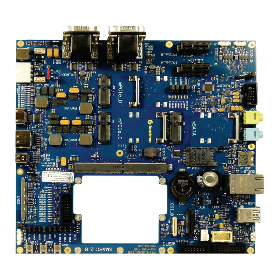
Kontron SMARC Eval-Carrier-2 Manuals
Manuals and User Guides for Kontron SMARC Eval-Carrier-2. We have
1
Kontron SMARC Eval-Carrier-2 manual available for free PDF download: User Manual
Kontron SMARC Eval-Carrier-2 User Manual (64 pages)
Brand:
Kontron
| Category:
Motherboard
| Size: 9.08 MB
Table of Contents
Customer Support
3
Revision History
3
Symbols
5
Table of Contents
8
List of Tables
9
List of Figures
9
1 / Introduction
11
2 / Description
12
Figure 1: Carrier Board with SMARC Interface
12
3 / Installation Procedure
13
3.1. Packing Check List
13
Requirements IEC60950-1
13
4 / System Specifications
14
4.1. Component Main Data
14
Table 1: Component Main Data
14
Table 2: Environmental Conditions
16
5 / Jumpers and Connectors
17
5.1. Hardware Configuration Setting
17
Table 3: Jumpers and Connectors
17
5.2. Mainboard Views and I/O Locations
18
Figure 2: Top View
18
Figure 3: Top View with Leds and Jumper
19
5.3. Front View
20
5.4. Front Left View
20
Figure 4: Front View
20
Figure 5: Front Left View
20
5.5. Front Right View
21
Figure 6: Front Right View
21
5.6. Rear Side
22
Figure 7: Rear Side from SMARC Eval-Carrier-2
22
6 / Block Diagram
23
Figure 8: Block Diagram for the SMARC Eval-Carrier-2
23
Figure 9: Red Jumper on Position INT
23
7 / Maintenance and Status Information
24
7.1. Leds
24
Table 4: Power Leds
24
Figure 10: Power Leds, See Board Position 21
24
Table 5: Backlight Voltage Leds
25
Table 6: GPIO Leds
25
Figure 11: GPIO and Backlight Leds, See Board Position 19
25
Table 7: Watchdog Leds
26
Table 8: Audio Selection Leds
26
Table 9: SATA Activity Leds
26
Table 10: Mpcie Slot a Leds
26
Table 11: Mpcie Slot B Leds
26
Figure 12: GPIO and Backlight Leds, See Board Position 25
26
8 / Pin Definitions
27
Table 12: Connector Definitions
27
SMARC Connector (J1)
28
Figure 13: 314-Pin SMARC Connector for SMARC-Interface
28
LVDS Connector (J3)
33
Figure 14: 30-Pin LVDS Connector
33
Backlight Connector (J40)
35
Figure 15: 7-Pin Backlight Connector
35
Edp Connector (Embedded Display Port) (J8)
36
Figure 16: 20-Pin Edp Connector
36
HDMI Connector (J42)
37
Figure 17: 19-Pin HDMI Connector
37
DP Connector (J12)
38
Mini Pcie Card Socket 1 (J13)
38
Figure 18: 20-Pin DP Connector
38
Figure 19: 52-Pin Mini Pcie Card
38
Mini Pcie Card Socket 2 (J20)
39
Figure 20: 52-Pin Mini Pcie Card
39
SIM Card Socket (J46)
41
Pcie X1 Connector 1 (J2)
41
Figure 21: 8-Pin SIM Card Socket
41
Figure 22: 52-Pin Pcie X1 Connector
41
Mini SATA Card Socket (J22)
42
Figure 23: 52-Pin SATA Card Socket
42
Audio Connector Line in (J24/J43)
43
Figure 24: Audio Jacks
43
Audio Connector (J10)
44
RTC Battery Holder (J37)
44
Figure 25: 9-Pin Audio Connector Header
44
Figure 26: RTC Battery Holder
44
Μusb 2.0 OTG Connector (J39)
45
J21 - USB Connections
45
Table 13: Pin Assignment
45
Table 14: Signal Description
45
Figure 27: Μusb 2.0 OTG Connector
45
Figure 28: USB 2.0 / 3.0 Socket
45
Figure 29: USB 2.0 High Speed Cable
46
Figure 30: USB 3.0 High Speed Cable
46
USB 2.0 Header (J59)
47
Figure 31: 9-Pin USB Header
47
Double USB 3.0 Connector (J21)
48
Figure 32: Double USB 3.0 Connector
48
LAN Connector (J36 and J41)
49
Figure 33: LAN Connector
49
Micro-Μsd Card Connector (J11)
50
Figure 34: Micro-Μsd Card Connector
50
UART-SER Connector (J29/J30)
51
Table 15: Top SER1/UART1
51
Table 16: Bottom SER0/UART0
51
Figure 35: Double D-SUB 9-Pin Connector
51
CAN Connector (J6/J7)
52
Table 17: Top SER3/UART3
52
Table 18: Bottom SER2/UART2
52
Figure 36: CAN_0/CAN_1 Connector
52
Camera Serial Interface (CSI0) Connector (J36)
53
Figure 37: 15-Pin Camera CSI Connector
53
Camera Serial Interface (CSI1) Connector (J61)
54
SMARC Eval-Carrier-2 - . Rev
54
Figure 38: 20-Pin Camera CSI Connector
54
GPIO Header (J38)
55
Figure 39: 2X8-Pin GPIO Header
55
Enhanced Serial Peripheral Interface Bus (Espi) Connector (J47)
56
Power Management Header (J45)
56
Figure 40: 2X7-Pin Espi Connector
56
Figure 41: 2X8-Pin Power Management Header
56
Fan Connector (J62)
57
Power-In Connector (J53)
57
Figure 42: 4-Pin Fan Connector
57
Figure 43: Power-In Connector
57
Module Power-In Connector (J54)
58
Figure 44: Module Power-In Connector
58
Figure 45: Red Jumper on Position INT
58
8.31. Button Switch
59
Table 19: Power Button (SW3, J26)
59
Table 20: Reset Button (SW1, J25)
59
Table 21: Force Recovery Button (SW4, J27)
59
Figure 46: Button Switch
59
8.32. Boot Selection Jumpers (J28, J32, J33) and Other Jumpers
60
Table 22: Boot Selection Jumpers
60
Table 23: Display Power Select Jumper (J4)
60
Table 24: Backlight Power Select Jumper (J23)
60
Table 25: LID Jumper (J34)
60
Figure 47: Jumpers for Boot Select
60
Table 26: TEST Jumper (J35)
61
Table 27: Leds Enable Jumper (J44)
61
Table 28: RESET Jumper (J25)
61
Table 29: Power Jumper (J26)
61
Table 30: Force Recovery Jumper (J27)
61
Table 31: Module Power Select Jumper (J55, J56, J57)
61
Figure 48: Module Power Select Jumper (J55, J56, J57)
61
Table 32: Audio Channel Jumper for I2S or HDA (J31)
62
Table 33: Mpcie-1WLAN Disable Jumper (J49, J50)
62
Table 34: Mpcie-1WLAN Disable Jumper (J51, J52)
62
Table 35: RTC Jumper (J58)
62
Figure 49: RTC Jumper (J58)
62
List of Acronyms
63
About Kontron
64
Advertisement
Advertisement
Related Products
Kontron ETX-C3
Kontron EPIC/PM
Kontron ETX-P3
Kontron ECX-BYT
Kontron ECX-KBL-U
Kontron ECX-APL
Kontron ETX-DC
Kontron ETXexpress UGM
Kontron SMARC-sAL28
Kontron COM Express Eval 10
Kontron Categories
Computer Hardware
Motherboard
Server
Desktop
PCI Card
More Kontron Manuals
Login
Sign In
OR
Sign in with Facebook
Sign in with Google
Upload manual
Upload from disk
Upload from URL