Table of Contents
Advertisement
Quick Links
Advertisement
Table of Contents

Related Manuals for Kontron EPIC/PM


Summary of Contents for Kontron EPIC/PM
- Page 1 Kontron User's Guide ® EPIC/PM ® Document Revision 1.15...
-
Page 3: Table Of Contents
About This Document ..................9 Copyright Notice ....................9 Trademarks ......................9 Standards ......................9 Warranty ......................9 Technical Support.................... 10 Introduction ......................11 EPIC/PM ......................11 The EPIC Family....................11 Getting started ......................12 Specifications ......................13 Functional Specifications.................. 13 Mechanical Specifications ................. 15 4.2.1 PC/104 Bus Connector (ISA part)................ 15 4.2.2... - Page 4 Display Power Considerations ................35 11.6 Connecting a LCD Panel ..................35 11.7 Configuration ....................36 11.8 Graphics Technical Support ................36 11.9 Available Video Modes..................36 11.9.1 Standard IBM-Compatible VGA Modes..............36 11.9.2 Extended VESA VGA Modes ................37 Kontron User's Guide EPIC/PM...
- Page 5 17.2.3 Register Description: ..................49 17.2.4 Output Waveforms ................... 52 17.3 SMBus Interface....................52 Fan Interface ......................53 18.1 CPU Fan Connector ..................53 18.2 CPU Fan Configuration..................53 18.3 Chassis Fan Connector ..................53 18.4 Chassis Fan Configuration ................. 54 Kontron User's Guide EPIC/PM...
- Page 6 23.3.1 Using Expanded Memory Managers ..............67 23.4 I/O Address Map ..................... 68 23.5 Peripheral Component Interconnect (PCI) Devices ..........69 Appendix B: BIOS Operation ..................70 24.1 Determining the BIOS Version................70 24.2 Configuring the System BIOS ................70 Kontron User's Guide EPIC/PM...
- Page 7 24.7.1 MultiBoot XP ....................86 24.7.2 Boot First Function ..................87 24.8 Exit Menu ...................... 88 24.9 Kontron BIOS Extensions .................. 88 24.9.1 JIDA BIOS extension ..................88 24.9.2 Remote Control Client Extension ................ 89 24.9.3 LAN PXE ROM ....................89 24.10 Updating or Restoring BIOS Using PhoenixPhlash..........
- Page 8 28.1.2 PCI ......................102 28.2 General PC Architecture .................. 102 28.3 Ports......................103 28.3.1 RS-232 Serial ....................103 28.3.2 ATA ......................103 28.3.3 USB ......................103 28.4 Programming ....................103 Appendix G: Document Revision History ..............104 Kontron User's Guide viii EPIC/PM...
-
Page 9: User Information
“as-is” and is subject to change without notice. For the circuits, descriptions and tables indicated, Kontron assumes no responsibility as far as patents or other rights of third parties are concerned. -
Page 10: Technical Support
Kontron Embedded Modules GmbH will not be responsible for any defects or damages to other products not supplied by Kontron Embedded Modules GmbH that are caused by a faulty Kontron Embedded Modules GmbH product. -
Page 11: Introduction
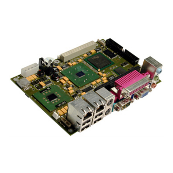
Introduction EPIC/PM The EPIC/PM hosts an Intel® Pentium® M processor in combination with an Intel® 855GME chipset with an integrated graphic memory controller hub. Celeron M versions of this board are possible, too. Two DDR-SDRAM-SODIMM sockets for up to 2 GB allows you to use standard DDR SODIMM memory modules. -
Page 12: Getting Started
3 2BGetting started Getting started Getting started with the EPIC/PM is very easy. For location of the connectors, see Appendix E: Connector Layout. Take the following steps: Turn off the power supply. Connect the power supply to the EPIC’s power supply connector. The board is available in a 10-pin ATX version. -
Page 13: Specifications
3 RS232C serial ports (1 DSUB9 at the front, 3 internal, 10-pin headers) ® 16550 compatible ® COM D configurable as RS422/485 ® One Parallel Port (LPT1) Enhanced Parallel Port (EPP) and Extended Capabilities Port (ECP) with bi-directional ® capability Kontron User's Guide EPIC/PM... - Page 14 LCD (Liquid Crystal Display) flat panel 2x24bit LVDS interface that uses JILI ® Audio Integrated in Intel® SoundBlaster™ AC97 ® Windows Sound System™ compatible ® 3 jack plugs (Line-in/Line-out/Mic). ® Extra standard Line-in connector (Motherboard-like) ® 5.1 Sound compatible ® Kontron User's Guide EPIC/PM...
-
Page 15: Mechanical Specifications
One 4 x 30 pin 2mm downward connector 4.2.3 Height on Top Max 32mm (1.26”) Height is depending upon CPU cooler/fan. 4.2.4 Height on Bottom Maximum 9.7mm (0.38”) 4.2.5 Weight About 320g (full featured version with passive CPU cooler, without DDR SDRAM) Kontron User's Guide EPIC/PM... -
Page 16: Electrical Specifications
4.3.3 Supply Current (typical) The EPIC/PM is equipped with power-saving features. Different power-consumption tests were executed to give an overview of the electrical conditions for several operational states. The board used a 512MB DDR SDRAM module. The attached hard disk was not supplied through the measurement path and no extension module was mounted on the system. -
Page 17: Supply Current (Maximum)
4 3BSpecifications EPIC/PM 1.8GHz ® Power Supply Operation State +5VStby DOS Prompt 4.00A 0.19A DOS Standby 2.34A 0.19A Windows Idle 2.50A 0.19A Windows Standby 1.03A 0.19A Windows 100% CPU Load 6.10A 0.19A 4.3.4 Supply Current (maximum) Power Supply Board +5VStby EPIC/PM 0.8GHz... -
Page 18: Real-Time Clock (Rtc) Battery
English, German, French, Danish, Finish and Spanish. If the battery is accessible by the end user, it is in the responsibility of the customer to give the corresponding safety instructions in the required language(s). Kontron User's Guide EPIC/PM... -
Page 19: Mtbf
Estimated RTC battery life (as opposed to battery failures) is not accounted for in the above figures and need to be considered for separately. Battery life depends on both temperature and operating conditions. When the Kontron unit has external power; the only battery drain is from leakage paths. Environmental Specifications 4.5.1... -
Page 20: Cpu, Chipset And Super I/O
Advanced Power Management features, including Enhanced Intel SpeedStep® ® technology (only for Pentium® M processors) Chipset The chipset of the EPIC/PM consists of the Intel® 855GME chipset GMCH (Graphics and Memory Controller Hub) and the Intel ® 82801DB ICH-4 (I/O Controller Hub 4). 5.2.1 GMCH (855GME Chipset) Processor/Host Bus Support Intel®... -
Page 21: Ich4 (82801Db)
Supporting up to 6 ports (4 available on EPIC board’s front, 2 on internal pin headers) AC-Link for AC’97 support Integrated IDE controller Ultra ATA/100/66/33 and PIO mode support ® Two channels for up to 3 devices with independent timing ® Kontron User's Guide EPIC/PM... -
Page 22: Super I/O
PS/2-Keyboard Controller and PS/2-Mouse Interface at board front plate ® 5V CPU Fan and 12V Chassis Fan ® CPU, Chipset and Super-I/O Configuration See the Advanced Menu and its submenus section of the Appendix B: BIOS chapter for information on possible settings. Kontron User's Guide EPIC/PM... -
Page 23: System Memory
6 5BSystem Memory System Memory The EPIC/PM supports 200-pin SODIMM DDR-SDRAM memory modules. Two sockets are available for 2.5V (power level), unbuffered double data rate synchronous dynamic random access memory (DDR-SDRAM) each up to 1024MB following Intel’s DDR266/PC2100 Specification. The supported devices on the DDR-SDRAM module must be 128-Mbit, 256-Mbit or 512-Mbit technologies chips. -
Page 24: Isa And Pci Bus Expansion
PC/104 bus and AT ISA bus is identical between C1 - C18 and D1 - D18. 7.1.1 PC/104 Connectors The EPIC/PM features the XT bus and AT bus extension on two, dual-row socket connectors with a 2.54mm x 2.54mm grid (0.1" x 0.1"). The PC-104 bus is available through Connectors X10B and X12A. -
Page 25: Pc/104-Plus (Pci Part)
7 6BISA and PCI Bus Expansion PC/104-Plus (PCI part) The EPIC/PM offers the PC/104-Plus bus on a quad-row female connector with a 2mm x 2mm (0.79” x 0.79”) pitch. This connector implements the standard 32-bit PCI bus signals. 7.2.1 PC/104-Plus Connector You can only use PC/104-Plus adapter boards on top of an EPIC/PM. -
Page 26: Keyboard And Mouse Interface
8 7BKeyboard and Mouse Interface Keyboard and Mouse Interface The EPIC/PM offers a PS/2-keyboard and PS/2-mouse interface on Connector X18. The upper interface is for the Mouse and the lower interface for the Keyboard connection. To find the location of the keyboard... -
Page 27: Ps/2-Mouse Configuration
You can set the PS/2 mouse to enabled, disabled or auto-detect from the BIOS Setup. If you enable the mouse, IRQ12 is used as the interrupt and is no longer available for other devices. Please refer to the Miscellaneous Submenu in the Appendix B: BIOS Operation chapter for additional information on configuration. Kontron User's Guide EPIC/PM... -
Page 28: Usb Interfaces
USB INTERFACES The EPIC/PM offers 6 USB ports. These ports are driven by either three UHCI USB 1.1 or one EHCI USB 2.0 controller(s). Four of the 6 USB ports are available on the EPIC/PM front, and two more ports are available on internal connectors. -
Page 29: Limitations Of Usb Ports 4 And 5
1. Some operating systems without USB 2.0 support do not work well with EHCI controller enabled. If you install such an OS at the EPIC/PM please disable the EHCI controller in the Setup Utility before installation. 2. For operating systems not listed on our Web site please contact your OS distributor for an USB 2.0 driver. -
Page 30: Ethernet Interface
10 9BEthernet Interface Ethernet Interface The EPIC/PM comes with two Ethernet interfaces. The first Ethernet interface uses the ICH4’s integrated 32-bit PCI LAN controller in combination with the Intel® 82562 platform LAN connect device. The second Ethernet interface uses the Single Chip Fast Ethernet NIC Controller Intel 82551ER. -
Page 31: Connectors
Connectors The 10/100Base-T interfaces are standard 8-pin RJ45 jacks. They are available at the front of the EPIC/PM through the multi-functional Connector X21 (Intel® 82562) and Connector X5 (Intel® 82551ER). To find the location of the Ethernet interfaces, please see the Appendix E: Connector Layout chapter. -
Page 32: Ethernet Technical Support
10 9BEthernet Interface You can download available drivers from the Kontron Web site. For further information read the read-me file or contact technical support. 10.5 Ethernet Technical Support If any problems occur, you can solve some of them by using the latest drivers for the Intel® LAN controller. -
Page 33: Graphic Interfaces
11.1 Video Controller The EPIC/PM uses the graphics accelerator integrated in the Intel® 855GM/GME chipset, which delivers high-performance 2D, 3D and video capabilities. With its interface to UMA (Unified Memory Architecture) up to 32MB of system memory are used as video memory. -
Page 34: Dvo Connector
Channel-B Flicker Blank DVOBFLDSTL Channel-B Field Stall DVOCVSYNC Channel-C Vertical Sync DVOCHSYNC Channel-C Horiz. Sync DVOCBLANK# Channel-C Flicker Blank DVOCFLDSTL Channel-C Field Stall DVOINT LCD Interrupt LTVDAT LCD/TV Data LTVCLK LCD/TV Clock VREF Reference Voltage (*) optional Kontron User's Guide EPIC/PM... -
Page 35: Flat Panel Lvds Interface (Jili) Connector
Display logic voltage and contrast voltage come pre-configured on the JILI cable. On occasion, backlight voltage has to be adjusted on the cable. Even though the EPIC/PM is also available as a +5V-only board, you need to supply the +12V for the backlight converter additionally when using such a converter type. -
Page 36: Configuration
Advanced Chipset Control submenu and the Display Control submenu in the Appendix B: BIOS Operation chapter for more configuration information. You can download drivers for the graphics controller from the Kontron Web site. For further information, read the read-me or help files or contact technical support. 11.8 Graphics Technical Support If problems occur, you can solve some of them by using the latest drivers for the graphics controller. -
Page 37: Extended Vesa Vga Modes
114h Graphics 800x600 115h Graphics 800x600 117h Graphics 1024x768 118h Graphics 1024x768 11Ah Graphics 1280x1024 11Bh Graphics 1280x1024 13Ah Graphics 1600x1200 13Ch Graphics 1920x1440 14Bh Graphics 1600x1200 14Dh Graphics 1920x1440 15Ah Graphics 1600x1200 15Ch Graphics 1920x1440 Kontron User's Guide EPIC/PM... -
Page 38: Serial-Communication Interfaces
Appendix E: Connector Layout chapter. 12.2 Onboard RS-232 Connector The following table shows the pin-out of COMA available at the front of the EPIC/PM board. Header Signal Name Function In / Out... -
Page 39: Connector
The base I/O-addresses 3F8h, 2F8h, 3E8h, or 2E8h can be configured when enabled, as well as the interrupts IRQ3, IRQ4, IRQ10 and IRQ11. COM D can be set to the RS232 or RS485 interface. Refer to the I/O Device Configuration submenu in the Appendix B: BIOS Operation chapter for information on configuration. Kontron User's Guide EPIC/PM... -
Page 40: Parallel-Port Interface
13 12BParallel-Port Interface Parallel-Port Interface The EPIC/PM incorporates an IBM XT/AT compatible parallel port. It supports uni-directional, bi- directional, EPP and ECP operating modes. 13.1 Connector The parallel port is available through the standard DSUB25 connector which is part of the multifunctional Connector X1 on the front. -
Page 41: Ide-Interfaces
14 13BIDE-Interfaces IDE-Interfaces PCI-bus devices serve as primary and secondary IDE hosts on the EPIC/PM. The controller supports: Up to Ultra DMA 100 mode ® Up to PIO mode 4 timing ® Multiword DMA mode 1 and 2 with independent timing ®... -
Page 42: Compactflash Socket
CompactFlash Socket The CompactFlash socket X13 for commercial CompactFlashes (Type I) is integrated on the bottom side of the EPIC/PM board. Because the signals of the socket are connected to the secondary IDE, the socket is not a hot-plug capable interface. Turn off power to the system before adding or removing a CompactFlash card. -
Page 43: Floppy Interface
Accessories are available for this interface from Kontron. To connect a standard 3.5” floppy drive, use an adapter cable (ADA-FLOPPY-2, Part Number 96001-0000-00-0). If you have a slim-line 3.5” floppy drive, you may need a flat foil cable (KAB-FLOPPY/MOPS-1, Part Number 96019-0000-00-0). -
Page 44: Connector Diagram
5.25” drive types with densities of 360kB, 720kB, 1.2MB, 1.25MB, 1.44MB or 2.88MB. Refer to the Main Menu section of the Appendix B: BIOS Operation chapter for more information on configuring the floppy drive. You also can disable the floppy-disk interface in the I/O Device Configuration Submenu. Kontron User's Guide EPIC/PM... -
Page 45: Sound Interface
® 16.1 Connectors The EPIC/PM offers two connectors related to the Sound feature. One is the jack connector on the front of the board and one is an internal connector. 16.1.1 Jack Connector The standard 3 position jack connector (X23) complies with the standard pin-out used in many commercially available motherboards. -
Page 46: Line-In/Rear Speakers Connector
Low Frequency output for multi-channel applications. 16.1.2 Line-In/Rear Speakers Connector Line-In or Rear Speaker signals (depending on the configuration) are always available on Connector X14. To find the location of the connector on the EPIC/PM board, please see the Appendix E: Connector Layout chapter. -
Page 47: Configuration
You can download available drivers for the sound controller from the Kontron Web site or use the drivers provided by the manufacturer Realtek. Search for ALC650 drivers for the required operating system and instructions on how to enable multi-channel support. -
Page 48: General Purpose I/O
This pin must not be pulled high within 50ms after PCIRESET# signal goes inactive. All of these signals are not galvanically isolated from the board. To ensure that the EPIC/PM Board is protected from electrical damage, implement external protection circuitry such as optocouplers at each signal. -
Page 49: 16-Bit Operating Systems
Kontron Web site. Detailed programming information about JIDA32 is beyond the scope of this document. Please refer to the JIDA32 documentation and the sample code, which is part of the JIDA32 package on the Kontron Web site. - Page 50 This register is a data port for output only. It reflects the outgoing logic levels of the pins whether the pins are defined as an output mode by CR0B. This register will reflect the value of output Flip-flop while read access. The output data will be inverted or changed output style by CR0A or CR0C. Kontron User's Guide EPIC/PM...
- Page 51 A read to this register will clear this register. CR13 - GP Port 2: Interrupt Enable Register Bit 5 … 0 0 to disable GP26-GP20 interrupt output when interrupt function is selected. Bit 7 … 6 Reserved Kontron User's Guide EPIC/PM...
-
Page 52: Output Waveforms
Depending on the register settings following output waveforms are possible on the GPIO pins. 17.3 SMBus Interface Pins 17 (SMB_DATA) and 18 (SMB_CLK) represent the SMBus interface of the System. Use these pins to communicate with the Smart Battery module if connected. Otherwise these pins must be left unconnected. Kontron User's Guide EPIC/PM... -
Page 53: Fan Interface
Fan Interface The EPIC/PM is normally shipped with a CPU fan. If for any reason no CPU fan is mounted or a different fan has to be used, use this interface to connect a fan to cool the CPU. The connector and onboard system controller support the speed monitoring of the fan. -
Page 54: Chassis Fan Configuration
The temperature measured can be either the CPU temperature or the system temperature which is measured within the SCH3114 controller. Setting this item to disabled means the fan will always run, except when the operating system takes control over it. Kontron User's Guide EPIC/PM... -
Page 55: Power Interface
EPIC/PM and need to be supplied, too, as soon as peripheral devices require these voltages. We recommend that you use an ATX power supply with this type of EPIC/PM, even though not all voltages are required. An adapter cable to connect a standard ATX power supply to this connector is available from Kontron (KAB-ATX-20TO10, Part Number 96072-0000-00-0). -
Page 56: At Connector Version
BIOS Operation chapter for more information on saving power. 19.2 ATX/Reset/2LED Interface This interface on the EPIC/PM is an 8-pin female (Connector X6). For the location of this connector see Appendix E: Connector Layout. The interface’s functions include: Power Button ®... -
Page 57: Configuration
When set to “power off” the power button offers an On/Off function and when set to “Sleep” it offers a Sleep/Wake function. Please refer to the Power menu section in the Appendix B: BIOS Operation chapter for more information about power savings. Kontron User's Guide EPIC/PM... -
Page 58: Watchdog Timer
20 19BWatchdog Timer Watchdog Timer The watchdog timer is integrated in the onboard SMSC SCH3114 controller of the EPIC/PM and can issue a reset to the system or generate a non-maskable interrupt (NMI). The watchdog timer circuit has to be triggered within a specified time by the application software. -
Page 59: Hardware Monitor
Appendix B: BIOS Operation chapter in this manual. To monitor the parameters of this feature from your operating system, Kontron recommends that you use the 32-bit protected mode JUMPtec’s Intelligent Device Architecture 32-bit driver (JIDA 32) with the test and demo application for Windows 95/98/ME/NT/2000/XP, which is available on the Kontron Web site. -
Page 60: Important Technology Information
Important Technology Information The following technological information is designed to give you a better understanding of some of the features offered by the EPIC/PM. This information can be referenced when reading the Appendix A: System Resource Allocations and Appendix B: BIOS Operation sections that follow. -
Page 61: Catastrophic Thermal Protection
Windows always runs at the highest performance state when the “Home/Office” or the “Always On” power scheme is selected. For more detailed information about processor performance control, see: - Chapter 8 of the ACPI Specification Revision 2.0c - Windows platform design notes Kontron User's Guide EPIC/PM... -
Page 62: Thermal Management
CPU and the thermal heuristics of the system. The ACPI thermal solution on EPIC/PM supports three cooling policies and their trip points: Active Trip Point Active cooling devices typically consume power and produce noise but are able to cool a thermal zone without limiting system performance. -
Page 63: I/O Apic Vs. 8259 Pic Interrupt Mode
The priority of interrupts in the I/O APIC is independent of the interrupt number. More interrupts The I/O APIC in the chipset of the EPIC/PM supports a total of 24 interrupts. Notes: The APIC is not supported by all operating systems. Only Windows XP supports APIC. -
Page 64: Native Mode Configuration
BIOS indicates that the controller can be switched, the controller supports native mode and the appropriate registry entry is set. You must add a DWORD VALUE called EnableNativeModeATA under HKEY_LOCAL_MACHINE/System/CurrentControlSet/Control/PnP/PCI/ and set 1 as the value. Kontron User's Guide EPIC/PM... -
Page 65: Appendix A: System-Resource Allocation
If the „used for“-device is disabled in setup, the corresponding interrupt is available for other devices. Possible setting for LPT1. IRQ7 is the default setting. Available in default configuration. IRQ 9 is used as SCI, if ACPI is enabled. Kontron User's Guide EPIC/PM... -
Page 66: Direct Memory Access (Dma) Channels
Note (1), (2) Note (1) Note (2) Cascade Notes: (1) If the „used for“-device is disabled in setup, the corresponding DMA channel is available for other devices. (2) Possible setting for LPT1 if configured for ECP mode. Kontron User's Guide EPIC/PM... -
Page 67: Memory Map
RAM. This is a bug of EMM386, not of the EPIC/PM. Please read the technical manuals of add-on cards used with the EPIC/PM for the memory areas they use. If necessary, exclude their memory locations to avoid a conflict with EMM386. -
Page 68: I/O Address Map
23.4 I/O Address Map The I/O-port addresses of the EPIC/PM are functionally identical with a standard PC/AT. All addresses not mentioned in this table should be available. We recommend that you do not use I/O addresses below 0110hex with additional hardware for compatibility reasons, even if available. -
Page 69: Peripheral Component Interconnect (Pci) Devices
Separate Bus, integrated in Intel chipset UHCI USB Controller INTD# Separate Bus, integrated in Intel chipset EHCI USB Controller INTH# Separate Bus, integrated in Intel chipset PCI to ISA bridge (AD18) REQ#4/GNT#4 82551ER Ethernet Controller (AD17) INTC# REQ#3/GNT#3 Kontron User's Guide EPIC/PM... -
Page 70: Appendix B: Bios Operation
24 23BAppendix B: BIOS Operation Appendix B: BIOS Operation The EPIC/PM comes with Phoenix BIOS 4.0, Release 6.1, which is located in the onboard Flash EEPROM in compressed form. The device has an 8-bit access. The shadow RAM feature offers faster access (16 bit). -
Page 71: Start Phoenix Bios Setup Utility
24 23BAppendix B: BIOS Operation BIOS setup menus represent those found in most models of the EPIC/PM. The BIOS setup utility for specific models can differ slightly. Note: Selecting incorrect values can cause system boot failure. Load setup-default values to recover by pressing <F9>. -
Page 72: Main Menu
System Memory bootup. Extended Memory * Displays amount of extended memory detected during bootup. Notes: In the Option column, bold shows default settings. Extended Memory = capacity of memory module – selected frame buffer memory size. Kontron User's Guide EPIC/PM... -
Page 73: Master Or Slave Submenus
In the Option column, bold shows default settings. (*) The CompactFlash IDE interface is not capable of running UDMA modes. On the 40 pin IDE interface an 80line UDMA 100 cable is required for proper operation in modes UDMA 3 and higher. Kontron User's Guide EPIC/PM... -
Page 74: Advanced Menu
8PCI/PNP ISA IRQ Resource Exclusion Sub menu Opens IRQ Exclusion sub menu. In a system with an AGP and a PCI video adapter end user can Default Primary Video Adapter select the adapter which will be initialized by the BIOS. Kontron User's Guide EPIC/PM... -
Page 75: Pci Device, Slot #X Submenu
In the Option column, bold shows default settings. IRQ9 is used for SCI in ACPI mode. Do not use IRQ9 for legacy ISA devices when ACPI enabled. (**) Entry is only visible when primary IDE or secondary IDE is disabled. Kontron User's Guide EPIC/PM... -
Page 76: Memory Cache Submenu
D800 – DBFF Write-Protect: Writes are ignored. Write Protected DC00 – DFFF Write-Back: Writes are cached but not sent to main memory until Write Back necessary. Note: In the Option column, bold shows default settings. Kontron User's Guide EPIC/PM... -
Page 77: I/O Device Configuration Submenu
EHCI driver is loaded. (**) If you want to use the USB boot feature, enable USB BIOS Legacy Support. A 16kb UMB area (most likely DC000h-DFFFFh) is used for USB BIOS Legacy Support. Kontron User's Guide EPIC/PM... -
Page 78: Lan Options
Enables the ICH4 internal LAN controller. Enabled Disabled Enables the remote boot BIOS extension for the onboard LAN Onboard LAN PXE ROM controller. Enabled Disabled Enables the wake on LAN BIOS extension for the onboard LAN Enable WOL Enabled controller. Kontron User's Guide EPIC/PM... -
Page 79: Sio Options
Select I/O base of port. Interrupt IRQ 5, IRQ 7 Select IRQ DMA channel DMA1, DMA3 Set the DMA channel for the parallel port in ECP mode Note: In the Option column, bold shows default settings. Kontron User's Guide EPIC/PM... -
Page 80: Keyboard Features Submenu
The time until the watchdog counter starts Delay counting. Useful to handle longer boot times. 10.5min, 30.5min 1s, 5s, 10s, 30s, 1min, 5.5min, Timeout Max. trigger period. 10.5min, 30.5min Note: In the Option column, bold shows default settings. Kontron User's Guide EPIC/PM... -
Page 81: Display Control Submenu
Determines which type of tests will be performed on memory above 1MB. Testing None Disabled If enabled, system comes up with a blank screen instead of the diagnostic Dark Boot screen during bootup. Enabled Halt On Errors Determines if post errors cause the system to halt. Kontron User's Guide EPIC/PM... - Page 82 The graphical logo stays up until just before the OS loads unless: You press <Esc> to display the POST screen ® You press <F2> to enter Setup ® POST issues an error message ® The BIOS or an option ROM requests keyboard input ® Kontron User's Guide EPIC/PM...
-
Page 83: Security Menu
In the Option column, bold shows default settings. (*) Enabling Supervisor Password requires a password for entering Setup. Passwords are not case sensitive. User and Supervisor passwords are related. A User password is possible only if a Supervisor password exists. Kontron User's Guide EPIC/PM... -
Page 84: Power Menu
® S5 (Soft off) ® The state S2 (sleeping with processor context not maintained) and S3 (Save to RAM) is not supported. The state S4 (Save to Disk) is a matter of the used operating system. Kontron User's Guide EPIC/PM... -
Page 85: Acpi Resume Events
(*) Disable ACPI support whenever you are using an operating system without ACPI capability. (**) See the chapter “Important Technology Information of this user’s guide for more details about these features. (***) EPIC/PM with Celeron M processor does not support TM2. Kontron User's Guide EPIC/PM... -
Page 86: Acpi Control Submenu
24.7 Boot Menu and Utilities MultiBoot is a boot utility integrated in the PhoenixBIOS 4.0. The EPIC/PM provides the MultiBoot XP version with integrated Boot First function. 24.7.1 MultiBoot XP MultiBoot XP comes with a complete new look of the Boot Device Priority submenu. This submenu is now... -
Page 87: Boot First Function
Override the existing boot sequence (for this boot only) by selecting another boot ® device. If the specified device does not load the OS, the BIOS reverts to the previous boot sequence. Enter Setup. ® Press <Esc> to continue with the existing boot sequence. ® Kontron User's Guide EPIC/PM... -
Page 88: Exit Menu
24.9 Kontron BIOS Extensions Besides the Phoenix System BIOS, the EPIC/PM comes with a few BIOS extensions that support special features. All extensions are located in the onboard flash EEPROM. Some extensions are permanently available; some are loaded if required during boot up. Supported features include: JIDA standard ®... -
Page 89: Remote Control Client Extension
If the onboard LAN PXE ROM is enabled in the system BIOS setup, a special optional ROM for the Ethernet controller loads into memory during boot up. This optional ROM allows you to boot the EPIC/PM over an Ethernet connection. A server with Intel PXE boot support is required on the other side of the Ethernet connection. -
Page 90: Updating Or Restoring Bios Using Phoenixphlash
PhoenixPhlash allows you to update the BIOS by using a floppy disk without having to install a new ROM chip. PhoenixPhlash is a utility used to flash a BIOS to the Flash ROM installed on the EPIC/PM. Use PhoenixPhlash to: Update the current BIOS with a newer version ®... -
Page 91: Preventing Problems When Updating Or Restoring Bios
For further information on the update key and the crisis diskette, see the Application Note PHLASH_SCE???, which is available from the KONTRON Embedded Modules Web site. The three question marks stand for the revision number of the file. -
Page 92: Appendix C: Block Diagram
25 24BAppendix C: Block Diagram Appendix C: Block Diagram Kontron User's Guide EPIC/PM... -
Page 93: Appendix D: Mechanical Dimensions
26 25BAppendix D: Mechanical Dimensions Appendix D: Mechanical Dimensions 26.1 Top View Dimensions on Mounting Holes and Pin 1 of each connector given in mm (mil) Kontron User's Guide EPIC/PM... -
Page 94: Front View
26 25BAppendix D: Mechanical Dimensions 26.2 Front View Kontron User's Guide EPIC/PM... -
Page 95: Appendix E: Connector Layout
27 26BAppendix E: Connector Layout Appendix E: Connector Layout 27.1 Top Side Notes: The position of Pin 1 of each connector can be seen in the previous chapter. Kontron User's Guide EPIC/PM... -
Page 96: Bottom Side
27 26BAppendix E: Connector Layout 27.2 Bottom Side Kontron User's Guide EPIC/PM... -
Page 97: Connector Functions And Interface Cables
For CompactFlash CompactFlash Connector IDE storage devices. 2mm 4 pos. For internal line-in Line-In Connector (Molex 87369-0400 or compatible) connection X15, X16, X17 Serial Interface 1.25mm 10 pos. KAB-DSUB9-3 For DSUB 9 Kontron User's Guide EPIC/PM... - Page 98 (AMP MTA-100 3-640440-3 or connection compatible) KAB-JILI-?????? For JILI interface JILI LVDS Interface (see separate cable list) cables DDR SDRAM SODIMM socket 2 2.54mm 3 pos. For Chassis fan Chassis Fan Interface (AMP MTA-100 3-640440-3 or connection compatible) Kontron User's Guide EPIC/PM...
-
Page 99: Pin-Out Table
PIDE_D1 DDCK /INIT /WDATA PIDE_D14 /SLIN PIDE_D0 /WGATE PIDE_D15 /TRK0 PIDE_DRQ /WRTPRT /PIDE_IOW /RDATA IOCS16 /PIDE_IOR /HDSEL PIDE_RDY PIDE_PD1 /PIDE_AK PIDE_IRQ /CS3 PIDE_A1 PIDE_ATAD /IOR PIDE_A0 /IOW PIDE_A2 /PIDE_CS1 /PIDE_CS3 PIDE_ACT /RESET IOCHRDY DACK SIDE_ACT ATADET Kontron User's Guide EPIC/PM... - Page 100 -- the enclosure of the peripheral device fulfils the fire-protecting requirements of IEC/EN 60950. (**) Do not connect anything to these signals. (***) The internal USB ports 4 and 5 are not protected on the power lines. An additional resetable fuse is recommended. Kontron User's Guide EPIC/PM...
- Page 101 To protect the external power lines of peripheral devices, make sure that: - the wires have the right diameter to withstand the maximum available current - the enclosure of the peripheral device fulfils the fire protecting requirements of IEC/EN 60950. Kontron User's Guide EPIC/PM...
-
Page 102: Appendix F: Pc Architecture Information
SAMS, 1990, ISBN 0-672-22722-3 The Indispensable PC Hardware Book, Hans-Peter Messmer, Addison-Wesley, 1994, ® ISBN 0-201-62424-9 The PC Handbook: For Engineers, Programmers, and Other Serious PC Users, John P. ® Choisser and John O. Foster, Annabooks, 1997, ISBN 0-929392-36-1 Kontron User's Guide EPIC/PM... -
Page 103: Ports
The Programmer’s PC Sourcebook, Second Edition, Thom Hogan, Microsoft Press, ® 1991, ISBN 1-55615-321-X Undocumented PC, A Programmer’s Guide to I/O, CPUs, and Fixed Memory Areas, ® Frank van Gilluwe, Second Edition, Addison-Wesley, 1997, ISBN 0-201-47950-8 Kontron User's Guide EPIC/PM... -
Page 104: Appendix G: Document Revision History
Changes EPBAM110 25.04.2006 Official release. EPBAM111 03.04.2007 Update of Chapter 19.1 . EPBAM112 30.07.2007 Updated Hyperlinks 17.12.2007 Updated to current Kontron Layout EPBAM113 29.02.2008 Released for web EPBAM114 10.04.2008 Ethernet restriction EPBAM115 30.04.2008 Memory RAM restriction Kontron User's Guide EPIC/PM...
Need help?
Do you have a question about the EPIC/PM and is the answer not in the manual?
Questions and answers