Table of Contents
Advertisement
Quick Links
Advertisement
Table of Contents

Related Manuals for Ancona Ancona Pro UC


Summary of Contents for Ancona Ancona Pro UC
-
Page 1: Range Hood
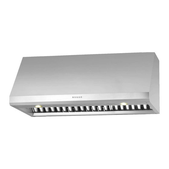
Range Hood Pro UC Electronic Controls User Manual & Installation Instructions IMPORTANT SAFETY INSTRUCTIONS Carefully read the important information regarding installation, safety and maintenance. Keep these instructions for future reference. -
Page 2: Before You Begin
Before You Begin INSTALLERS - Start Here Safety Instructions are on pages 4 and 5 and Installation Instructions are on pages 6 to 14. Please perform these steps: 1. Read the safety instructions. 2. Read all instructions in the Installation section of this manual BEFORE installing the range hood. -
Page 3: Table Of Contents
Table of Contents Before You Begin ..........................2 Table of Contents ..........................3 Important Safety Information ......................4 Included Parts ........................... 6 Range Hood Dimensions ........................7 Specifications ............................ 7 Installation ............................6 Step 1 - Read the Safety Instructions .................... 8 Step 2 - Unpack Range Hood and Prepare Tools ................ -
Page 4: Important Safety Information
Important Safety Information READ ALL INSTRUCTIONS BEFORE USE Read and follow all instructions before using the range hood to prevent the risk of fire, electric shock, personal injury, or damage when using the range hood or appliances with the range hood. This guide does not cover all possible conditions that may occur. - Page 5 Important Safety Information WARNING: TO REDUCE RISK OF A RANGE To reduce the risk of injury to persons in the TOP GREASE FIRE: event of a gas leaks: a) Never leave surface units unattended at high • Extinguish any open flame. settings. Boilovers cause smoking and greasy • DO NOT turn on the lights or any type of appliance.
-
Page 6: Included Parts
Included Parts Range Hood Damper Baffle Filters 30” x 2 Damper Adapter Damper Screws x 4 Baffle Filters 36” x 3 (already installed) Wood Support Grease Tray 30” x 2 Grease Tray 36” x 3 Hardware Note: For safety reasons, range hood mounting screws and anchors will not be included due to the variation of cabinetry constructions and wall material. -
Page 7: Range Hood Dimensions
Range Hood Dimensions 12-1/8” (310 mm) 2” (35 mm ) Specifications Body Design Stainless Steel Power Rating 120 V / 60 Hz (cETLus Certified) Total Input Power 540 W Motor Input Power 500 W Total Amps 4.5 A Speed Control Levels 4 Levels Interference Levels Radio Frequency Interference Protected Airflow 850 CFM Motors... -
Page 8: Installation
Installation STEP 1 Read the Safety Instructions • It is very important to read the safety instructions on pages 4 and 5. IMPORTANT: It is the installer’s responsibility to comply with installation clearances. STEP 2 Unpack Range Hood and Prepare Tools • Carefully unpack the range hood and parts. -
Page 9: Step 5 - Venting Installation Guides
Installation STEP 5 Venting Installation Guidelines IMPORTANT: For the most efficient and quiet operation: • Vent system must terminate to the outside (roof or side wall). • It is recommended that the range hood be vented • DO NOT terminate the vent system in an attic or other vertically through the roof through 10” (15.3 cm) or enclosed area. bigger round metal/aluminum vent work. -
Page 10: Step 6 - Install Wood Support
Installation STEP 6 Install Wood Support • Locate at least two vertical studs at the wood mounting location by tapping drywall or by using a stud finder. • Position the supplied wood support 3” (76 mm) below the cabinet and drill 1/8” (3.175 mm) pilot holes through the support, drywall and into the studs. -
Page 11: Step 8 - Mount The Range Hood
Installation STEP 8 Mount the Range Hood • Lift the range hood and place over the protruding mounting screws; the keyhole slots on the top of the range hood should engage with the protruding mounting screws. • Gently slide the range hood backwards until it cannot slide back any further. Finish screwing in the mounting screws. Notes: • Please make sure to read ALL safety precautions on pages 4 and 5. -
Page 12: Step 10 - Install Damper Adapter And Damper
Installation STEP 10 Install Damper • Position the damper over the damper adapter and secure using the screws provided. f DAMPER f WALL f DAMPER ADAPTER STEP 11 Connect Ductwork • Attach ductwork to damper. Secure the ductwork with duct tape to make joints are secure and air- tight. • Do not install the duct tape too tightly as this may prevent the damper flaps from opening which will overwork the motor and cause improper functioning of the unit. -
Page 13: Step 12 Connect To Ac
Installation STEP 12 Connect to AC 3-Pronged Plug • Connect AC plug into a grounded AC outlet having 120V, 60Hz. Place the outlet at a maximum distance of 33-1/2” (851 mm) from where the cord exits on the hood. Ground Plug • SEE IMPORTANT INSTRUCTIONS BELOW 3-Prong Receptacle IMPORTANT: • Observe all governing codes and ordinances. -
Page 14: Step 13 - Install Grease Trays
Installation STEP 13 Install Grease Trays • Place the grease trays into the the track at the back of the range hood. • Slide them left and right until all trays are placed side-by-side in the track. • The baffle filters and grease trays should be cleaned once a month, or as needed. -
Page 15: Operation
Operation Using the Fan Turning the Light On of Off Press the button to Press the button to turn on the fan and set it turn the light on. to slow speed; the button will light up. Press the button to Press the button increase the speed to the... -
Page 16: Maintenance
Maintenance Replacing the Light Bulbs Cleaning the Range Hood Unplug the unit from the AC outlet. Be sure electrical power is off and all surfaces are cool before cleaning or servicing any part of the hood. Gently remove the metal ring around the light using a flat-head screwdriver. -
Page 17: Replacement Parts
Replacement Parts 16A & 16B Description Part Code Description Part Code 1 - Capacitor PACAP-15 11 - Light Panel 30”* PALPL-20 12 - Light Panel 36”* PALPL-21 2 - Circuit Board PABRD-14 3 - Control Panel PACPL-15 13 - Hardware Bag* PASCR-16 4 - Transformer PATRA-13... - Page 18 Ancona is in association with Mr Appliance for all after sales service calls. Please contact their service provider or visit their website: Phone: 888-998-2011 Website: www.mrappliance.com MAAN-1230-02 © 2015 Copyright of Ancona Home. All rights reserved. This material may not be reproduced, displayed, modified or distributed. — 18 —...
Need help?
Do you have a question about the Ancona Pro UC and is the answer not in the manual?
Questions and answers