Table of Contents

Related Manuals for Ancona Pro Pyramid


Summary of Contents for Ancona Pro Pyramid
-
Page 1: Range Hood
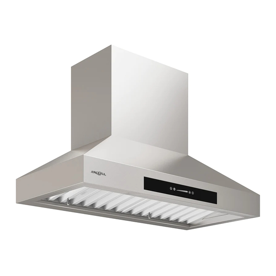
Range Hood Pro Pyramid User Manual & Installation Instructions IMPORTANT SAFETY INSTRUCTIONS Carefully read the important information regarding installation safety and maintenance. Keep these instructions for future reference. -
Page 2: Before You Begin
Before You Begin INSTALLERS - Start Here Safety Instructions are on pages 4 and 5 and Installation Instructions are on pages 6 to 16. Please perform these steps: 1. Read the safety instructions. 2. Read all instructions in the Installation section of this manual BEFORE installing the range hood. -
Page 3: Table Of Contents
Table of Contents Before You Begin ..........................2 Table of Contents ..........................3 Important Safety Information ......................4 Installation ............................6 Included Parts ........................... 6 Range Dimensions ..........................7 Specifications ............................ 7 Step 1 - Read the Safety Instructions ....................8 Step 2 - Unpack the Range Hood and Prepare Tools ............... -
Page 4: Important Safety Information
Important Safety Information READ ALL INSTRUCTIONS BEFORE USE Read and follow all instructions before using the range hood to prevent the risk of fire, electric shock, personal injury, or damage when using the range hood or appliances with the range hood. This guide does not cover all possible conditions that may occur. - Page 5 Important Safety Information WARNING: TO REDUCE RISK OF A RANGE To reduce the risk of injury to persons in the TOP GREASE FIRE: event of a gas leaks: a) Never leave surface units unattended at high • Extinguish any open flame. settings. Boilovers cause smoking and greasy • DO NOT turn on the lights or any type of appliance.
-
Page 6: Installation
Installation Included Parts Main housing Damper Hardware Screw Kit* Damper Gasket Baffle Filter x 2 Motor Body Baffle Filter for 36” x3 Grease Tray x 2 Grease Tray for 36” x3 Lower Chimney Upper Chimney Bracket Upper Chimney Screw Note: For safety reasons, screws and anchors for mounting will not be included due to the variation of cabinetry constructions and wall material. -
Page 7: Range Dimensions
Installation Range Dimensions 15 5/8” 13 9/16” (397mm) (345mm) 3 1/2” (90mm) 20 1/4” 29 7/8” / 35 3/8” (515mm) (760mm / 900mm) Specifications Body Design Stainless Steel Power Rating 120 V / 60 Hz (cETLus Certified) Total Input Power 438 W Motor Input Power 432 W Amperage 3.72 A 775 CFM... -
Page 8: Step 1 - Read The Safety Instructions
Installation STEP 1 Read the Safety Instructions It is very important to read the safety instructions on pages 4 and 5. IMPORTANT: It is the installer’s responsibility to comply with installation clearances. STEP 2 Unpack the Range Hood and Prepare Tools Unpack the range hood and parts carefully and make sure all parts are included as shown on page 6. -
Page 9: Step 5 - Figure Proper Venting
Installation STEP 5 Figure Proper Venting IMPORTANT: For the most efficient & quiet operation: • Vent system must terminate to the outside (roof or side wall). • It is recommended that the range hood be vented • DO NOT terminate the vent system in an attic or other vertically through the roof through 10” (15.3 cm) or enclosed area. -
Page 10: Step 6 - Put Motor Housing Upside Down On A Flat Surface
Installation Before installing, please visit anconahome.com or scan the QR code to watch the installation video STEP 6 Put motor housing upside down on a flat surface Place cube shaped foam from the packaging underneath the motor body for stability. Then place motor body on a flat surface as shown below, ideally on the floor. -
Page 11: Step 7B - Insert Motor Body Inside Main Housing
Installation STEP 7b Insert motor body inside main housing The main housing and motor body are similar in size. We recommend the following steps to ensure correct fitting. Insert the motor body (A) into the corner of the main housing (B) highlighted in figure 1. Figure 1 Rotate the main housing (B) counter-clockwise at a 45° angle and then tilt main housing (B) downwards until motor body (A) is completely inside. -
Page 12: Step 8 - Screw Two Sections
Installation STEP 8 Screw two sections Align the screw holes and screw the two pieces together using the screws provided. (See figure 6 ) STEP 9 Connect the connectors Connect the quick connectors at the back of the unit. STEP 10 Mark Placement of Mounting Screws Mark placement of mounting screws. -
Page 13: Step 11 - Place Hood On Mounting Screws
STEP 11 Place Hood on Mounting Screws Place the range hood’s key holes securely on the mounting screws and then tighten screws. STEP 12 Install Damper Place damper and damper gasket on top of ventilation hole, then connect using the four screws (included). STEP 13 Install Ductwork Attach ductwork to damper then duct tape the ductwork to make joints secure and air- tight. -
Page 14: Step 15 - Install Bracket And Upper Chimney
Installation STEP 15 (Optional, depending on ceiling height) Install Upper Chimney Bracket and Upper Chimney Screw upper chimney bracket on the wall above the range hood directly below the ceiling, using three wood screws, making sure to screw them directly into studs. If studs are not available, you can use wall anchors. Place the upper chimney inside lower chimney. -
Page 15: Step 16 Connect To Ac
Installation STEP 16 Connect to AC 3-Pronged Plug Connect AC plug into a grounded AC outlet having 120V, 60Hz. Place the outlet at a maximum distance of 33-1/2” from where the cord exits on the hood. SEE IMPORTANT INSTRUCTIONS BELOW. Ground Plug 3-Prong Receptacle IMPORTANT: • Observe all governing codes and ordinances. • It is the customer’s responsibility to contact a qualified electrical installer. • If codes permit and a separate ground wire is used, it is recommended that a qualified electrician determine that the ground path is adequate. A 120-Volt, 60 Hz, AC-only, fused electrical supply is required on a separate 15-amp circuit, fused on both sides of the line. -
Page 16: Step 17 - Install Grease Trays
Installation STEP 17 Install Grease Trays Slide the grease trays as shown, installed side by side. The baffle filters and grease trays should be cleaned once a month, or as needed. See page 18 to clean. To replace the grease trays: Place and seat the drip tray into the hood rack. -
Page 17: Operation
Operation Using the Fan Turning the Light Press the button to On or Off turn the unit on. Press the button to turn the unit on. Press the button to turn on the fan. Press the button Touch the sensor to select to turn the light on. -
Page 18: Replacing The Puck Light
Operation Replacing the Puck Light Cleaning the Range Hood Unplug the unit from the AC outlet. Be sure electrical power is off and all surfaces are cool before cleaning or servicing any part of the hood. Main Hood Remove five screws from the light panel, then remove the puck light by popping it out. -
Page 19: Replacement Parts
Replacement Parts Description Part Code Description Part Code 1 - Capacitor PACAP-15 11 - Light Panel 30”* PALPL-20 12 - Light Panel 36”* PALPL-21 2 - Circuit Board PABRD-14 3 - Control Panel PACPL-15 13 - Hardware Bag* PASCR-16 4 - Transformer PATRA-13 14 - Baffle Filter - 30”* please advise... - Page 20 Ancona is in association with Mr Appliance for all after sales service calls. Please contact their service provider or visit their website: Phone: 888-686-0778 Website: www.mrappliance.com MAAN-1137-02 © 2015 Copyright of Ancona Home. All rights reserved. This material may not be reproduced, displayed, modified or distributed. — 20 —...
- Page 21 10 a 12 dans le livret pour les instructions. MAAN-1137-02 © 2015 Copyright of Ancona Home. All rights reserved. This material may not be reproduced, displayed, modified or distributed. — 21 —...
Need help?
Do you have a question about the Pro Pyramid and is the answer not in the manual?
Questions and answers
The lights come on when you touch 1,2,3 or 4 but not when you touch the light button. The fan does not come on anytime.
If the lights do not turn on with the light button and the fan does not operate, the issue could be that the unit is not receiving electrical power. Check if the unit is properly plugged into the AC outlet and ensure the power is on. Also, verify that the circuit breaker has not tripped.
This answer is automatically generated