
Related Manuals for Ancona SP


Summary of Contents for Ancona SP
- Page 1 MODEL: SP Range Hood IMPORTANT SAFETY INSTRUCTIONS Carefully read the following important information regarding installation safety and maintenance. Keep these instructions for future reference. 20/05/2015 MAAN-1223-4...
-
Page 2: Important Safety Notice
IMPORTANT SAFETY NOTICE READ AND SAVE THESE INSTRUCTIONS READ ALL INSTRUCTIONS BEFORE INSTALLING AND OPERATING THIS APPLIANCE The installation in this manual is intended for qualified installers, service technicians or persons with ● similar qualified background. Installation and electrical wiring must be done by qualified professionals and in accordance with all applicable codes and standards, including fire-rated construction. - Page 3 IMPORTANT SAFETY NOTICE READ AND SAVE THESE INSTRUCTIONS READ ALL INSTRUCTIONS BEFORE INSTALLING AND OPERATING THIS APPLIANCE WARNING: TO REDUCE RISK OF A RANGE TOP GREASE FIRE: a) Never leave surface units unattended at high settings. Boilovers cause smoking and greasy spillovers that may ignite.
-
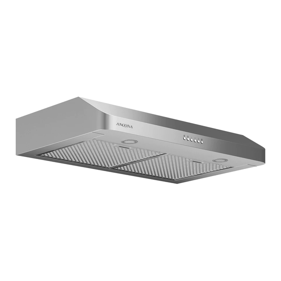
Page 4: Parts Supplied
PARTS SUPPLIED: Vent / Damper Filters (2 pcs) Mounting Screws Mounting Screws (4 pcs) (10 pcs) Washers (4 pcs) - Page 5 VENTING REQUIREMENTS: HEIGHT & CLEARANCE: • Vent system must terminate to the outside (Roof or side wall). • DO NOT terminate the vent system in an attic or other enclosed area. • DO NOT use 4” (10.2 cm) laundry-type wall caps.
-
Page 6: Calculating Vent System Length
IMPORTANT: • A minimum of 6” round or 3-1/4 x 10” rectangular duct (purchased separately) must be used to maintain maximum airflow efficiency. • Always use rigid type metal/aluminum ducts if available to maximize airflow when connecting to provided duct. •... -
Page 7: Venting Methods
VENTING METHODS: • This range hood is factory set for venting through the roof or wall. • Vent work can terminate either through the roof or wall. To vent through a wall, a 90° elbow is needed. IMPORTANT: NEVER exhaust air or terminate duct work into spaces between walls, crawl spaces, ceiling, •... -
Page 8: Electrical Requirements
ELECTRICAL REQUIREMENTS: IMPORTANT: Observe all governing codes and ordinances. It is the customer’s responsibility to contact a qualified electrical installer. If codes permit and a separate ground wire is used, it is recommended that a qualified electrician determine that the ground path is adequate. A 120-Volt, 60 Hz, AC-only, fused electrical supply is required on a separate 15-amp circuit, fused on both sides of the line. - Page 9 PREPARATIONS: Advanced Preparations: • Be familiar with the controls of the range hood by reading through Range Hood Operations, Page 14. • Place the range hood on a flat, stable surface. Connect the range hood to a designated standard outlet (120-Volt, 60Hz, AC only) and turn on the range hood.
- Page 10 NEW INSTALLATION: ep 5: Venting Installations (refer to Page 4 for parts): NOTE: Use threaded drywall anchors only when mounting the hood on sheet rock. Mounting the hood on wall studs or lumbars is highly recommended. Step 1: Create Exterior Ventilation •...
- Page 11 NEW INSTALLATION: Fig #6 Step 5: Installing the Hood • Using measurements provided on Page 15, measure and drill 4 holes into bottom of cabinet. (See Fig #6) • Depending on exterior venting chosen (See page 7), use measurements provided on Page 16 and cut vent hold in cabinet. •...
- Page 12 REPLACEMENT INSTALLATION: ep 5: Venting Installations (refer to Page 4 for parts): NOTE: Use threaded drywall anchors only when mounting the hood on sheet rock. Mounting the hood on wall studs or lumbars is highly recommended. Step 1: Measuring • Measure the distance between the cooking surface and the bottom of the range hood. A distance of 24”...
- Page 13 REPLACEMENT INSTALLATION: Fig #6 Step 4: Installing the Hood • Using measurements provided on Page 15, measure and drill 4 holes into bottom of cabinet. (See Fig #6) • Depending on exterior venting chosen (See page 7), use measurements provided on Page 16 and cut vent hold in cabinet. •...
-
Page 14: Control Panel Operation
CONTROL PANEL OPERATION: This range hood is equipped with six electronic controls, an Easy Clean Panel, two aluminum mesh filters with stainless steel panels, and two bright LED lights. The six electronic buttons control the intensity of the Lights, Speeds (Quiet, Low, Medium and High) and Power (On/Off). - Page 15 MEASUREMENTS AND DIAGRAMS: 1 3/4’’ (4.5 cm)
-
Page 16: Troubleshooting
TROUBLE SHOOTING: 1) If the range hood or halogen light does not • Check if the range hood has been plugged in, operate after installation: make sure that all power has been turned back ON,fused not blown and all electrical wiring are properly connected. -
Page 17: Range Hood Assembly
RANGE HOOD ASSEMBLY: 21 Wires 10 Capacitor 20 LED Puck Lights 9 Electronic Box Cover 19 Light Panel 8 Switch Box Cover 18 Filters 7 Switch Buttons 17 Safety Screen 6 Switch PCB 16 Easy Clean Panel 5 Switch Box Base 15 Propeller Cage 4 Switch Bracket 14 Propeller... -
Page 18: Specifications
SPECIFICATIONS: Stainless steel Body design 120V / 60Hz (USA & Canada standard) cETLus Certified Power rating 108W Total input power 100W Motor input power 0.85A Total Ampere 4 levels Levels of speed control Interference Protection Radio frequency interference protected Low Speed 2.0 Sones Noise Level Number of Motor Single motor... -
Page 19: Blower Assembly
BLOWER ASSEMBLY: Description Description Propeller Cage Safety screen Motor Propeller ELECTRICAL ASSEMBLY: Description Description Electronic box cover Electronic box bracket Capacitor LED driver Electronic box base... - Page 20 USE AND CARE INFORMATION: Operations: • Read and understand all instructions and warnings in this manual before operating the appliance. Save these instructions for future reference. • Always leave safety grills and filters in place. Without these components, operating fans could catch on to hair, fingers and loose clothing.
Need help?
Do you have a question about the SP and is the answer not in the manual?
Questions and answers
how to replace light bulb and light panel removal.
To replace the light bulb and remove the light panel for the Ancona SP range hood:
1. Ensure the power is turned off at the service panel and the panel is locked to prevent accidental power-on.
2. Remove the two filters and the easy-clean panel to access the inside of the unit.
3. While the lights are OFF, press the Light Control button once to turn the lights ON if needed for testing after replacement.
No specific steps for removing the light panel or replacing the bulb are detailed beyond removing filters and the easy-clean panel to access the inside.
This answer is automatically generated