Table of Contents
Advertisement
Quick Links
Advertisement
Table of Contents

Subscribe to Our Youtube Channel
Related Manuals for Ancona UC64NL


Summary of Contents for Ancona UC64NL
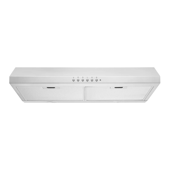
- Page 1 Range Hood UC64NL 30 inch User Manual & Installation Instructions IMPORTANT SAFETY INSTRUCTIONS Carefully read the important information regarding installation, safety and maintenance. Keep these instructions for future reference. MAAN1227-01 2019-06-19...
-
Page 2: Before You Begin
Before You Begin INSTALLERS - Start Here Safety Instructions are on pages 4 to 6 and Installation Instructions are on pages 9 to 17. Please perform these steps: 1. Read the safety instructions. 2. Read all instructions in the Installation section of this manual BEFORE installing the range hood. -
Page 3: Table Of Contents
Table of Contents Before You Begin ..........................2 Table of Contents ..........................3 Important Safety Information ......................4 Included Parts ........................... 7 Range Hood Dimensions ........................8 Specifications ............................ 8 Installation ............................9 Step 1 - Read the Safety Instructions .................... 9 Step 2 - Unpack Range Hood and Prepare Tools ................ -
Page 4: Important Safety Information
Important Safety Information READ ALL INSTRUCTIONS BEFORE USE Read and follow all instructions before using the range hood to prevent the risk of fire, electric shock, personal injury, or damage when using the range hood or appliances with the range hood. This guide does not cover all possible conditions that may occur. - Page 5 Important Safety Information WARNING: TO REDUCE RISK OF A RANGE To reduce the risk of injury to persons in the TOP GREASE FIRE: event of a gas leaks: a) Never leave surface units unattended at high • Extinguish any open flame. settings. Boilovers cause smoking and greasy • DO NOT turn on the lights or any type of appliance.
- Page 6 Important Safety Information WARNING: TO REDUCE RISK OF A RANGE 7. Two installers are recommended because of TOP GREASE FIRE: the large size and weight of this hood. 1. To reduce risk of fire and to properly exhaust 8. This product is equipped with a thermostat air, be sure to duct air outside. Do not vent which may start blower automatically.
-
Page 7: Included Parts
Included Parts Range Hood Vent-round Vent-rectangle Metal Cover Rectangle bracket 2 Filters 9 + 1 Mounting Screws (8MM) Hardware Note: For safety reasons, range hood mounting screws and anchors will not be included due to the variation of cabinetry constructions and wall material. Please consult your installation specialist regarding the optimal type of mounting screws and wall anchors to suit your home’s construction. -
Page 8: Range Hood Dimensions
Range Hood Dimensions 8.3 cm (3 1/4 in.) Specifications Body Design Stainless Steel Power Rating 120 V / 60 Hz (cETLus Certified) Total Input Power 140 W (135 W + 2 x 2.5 W) Motor Input Power 135 W Amperage 1.3 A Speed Control Levels 3 Speeds Interference Protection Radio Frequency Interference Protected Motors... -
Page 9: Installation
Installation STEP 1 Read the Safety Instructions • It is very important to read the safety instructions on pages 4, 5 and 6. IMPORTANT: It is the installer’s responsibility to comply with installation clearances. STEP 2 Unpack Range Hood and Prepare Tools • Carefully unpack the range hood and parts. -
Page 10: Step 5 - Venting Installation Guidelines
Installation STEP 5 Venting Installation Guidelines • The following steps are for exterior ventilation. IMPORTANT: For the most efficient and quiet operation: • Vent system must terminate to the outside (roof or side wall). • It is recommended that the range hood be vented • DO NOT terminate the vent system in an attic or other vertically through the roof through 6 in. - Page 11 Installation IMPORTANT: for gas stove tops and no higher than 30-inch (76.2 cm) • A minimum of 6 in. (15.3 cm) round or 3-1/4 x 10 in. (8.3 cm for electric cook tops. x 25.4 cm) rectangular duct (purchased separately) must be • It is important to install the hood at the proper mounting used to maintain maximum airflow efficiency.
-
Page 12: Step 6 - Preparations
Installation STEP 6 Preparations NOTE: To avoid damage to your hood, prevent debris from entering the vent opening. • Determine and mark the center line on the ceiling or wall where the range hood will be installed. • Make sure there is proper clearance within the ceiling or wall for exhaust vent. • Due to the weight and size of this unit, please make sure that the support system or framework being used is stable and secure in the ceiling or wall. -
Page 13: Step 9 - Attaching Vent
Installation • A metal cover is included, to protect the motor. To install, loosen and remove the 4 screws, then put the metal cover on and tighten the screws. Fig #3 STEP 9 Attaching Vent • There are 3 venting ways, with 2 type of damper options, one is 6 in. round (15.3 cm), another is 3 1/4 x 10 in. (8.3 cm x 25.4 cm) rectangle. - Page 14 Installation Top venting using rectangular damper • If you require rectangular top (vertical) venting simply install the rectangular damper provided (See Fig #8, #9 and #10). Use screws 4*8MM to connect damper. Fig #8 Fig #9 Fix rectangle damper to the top by screws 4*8MM Fig #10 Rear venting (horizontal) using rectangular damper...
-
Page 15: Step 10 - Installing The Hood
Installation STEP 10 Installing the Hood Method 1: Attaching the unit to the wall • The following drawings show the mounting dimensions of the 30 in. (750 mm). • Mark or drill 4 small holes on the mounting position according to the dimensions on Fig #14. • Insert 4 drywall anchors into the holes, and 2 screws into the top holes. -
Page 16: Step 11 Venting
Installation STEP 11 Venting • Depending on exterior ventilation chosen (see page 10), either exit the ducting through the ceiling or wall. • Always use rigid type metal/aluminum duct tube (follow the building codes in your area) to maximize airflow. Make sure that the backdraft flaps can open, to allow maximum airflow. Connect the duct tube to the vent/damper and securely seal with certified aluminum or foil tape so that it is air tight. Please check the building codes in your city to learn which tape product is recommended. -
Page 17: Step 12 - Install Filters
Installation STEP 12 Install Filters To install filters for the following four steps (See Figure #18): • Angle the filter into slots at the back of the hood. • Push the button on handle of the filter. • Release the handle once the filter fits into a resting position. • Repeat to install all filters. -
Page 18: Operation
056B 056B 056B 013B 056B 056B 056B 056B Operation 013B 013B 056B 056B 056B 056B 056B 056B 056B 013B 013B 013B 013B Lamp Auto Timer Decrease Increase Power 056B (On/off) NOTE: When the hood has been initially connected to the 013B 013B 013B... -
Page 19: Maintenance
Maintenance Replacing the Light Bulbs IMPORTANT: ALWAYS SWITCH OFF THE ELECTRICITY SUPPLY AT THE MAIN PANEL BEFORE CARRYING OUT ANY OPERATION ON THE APPLIANCE. Make sure the range hood is unplugged or turn OFF Replace with a 10.2 Volt, 2.5 Watt max, LED lights. breaker. -
Page 20: Range Hood Assembly
Range Hood Assembly Number Part Damper flap (rectangle) Vent (rectangle) Damper flap (round) Vent (round) Rectangle bracket Housing assembly Motor bracket Slot Motor Wheel Metal ring Metal cover Filter (1 set with 2 pieces) LED puck lights Screw bag Terminal cap Cover of control box Control board Control button Control box... -
Page 21: Assembly
Assembly Circuit Diagram Motor 0V 60Hz Capacitor Main PCB _ _ _ LED Pucks CH B MAX 10.2V 250mA 2.5W Temperature / Humidity Sensor (Optional) Blower Assembly Number Part Ring Blower Propeller Motor Bracket of motor Electrical Assembly Number Part Bracket of electronic box Base of electronic box Capacitor... -
Page 22: Troubleshooting
Troubleshooting Problem Cause Solution Light on, but motor does not The motor blocked Get rid of the blocking work The capacitor is damaged Have capacitor replaced The motor bearings are jammed Have motor replaced or damaged Light does not work, motor does Beside the mentioned above, check the following: not work Light is damaged... -
Page 23: Use And Care Information
Use and Care Information Operations • Read and understand all instructions and warnings in this manual before operating the appliance. Save these instructions for future reference. • Always leave safety grills and filters in place. Without these components, operating fans could catch on to hair, fingers and loose clothing. - Page 24 Ancona is in association with Mr Appliance for all after sales service calls. Please contact their service provider or visit their website: Phone: 1-888-998-2011 Website: www.mrappliance.com MAAN1227-01 © 2019 Copyright of Ancona Home. All rights reserved. This material may not be reproduced, displayed, modified or distributed. — 24 —...
Need help?
Do you have a question about the UC64NL and is the answer not in the manual?
Questions and answers