
Related Manuals for GSS GSS.mux SMCIP 401


Summary of Contents for GSS GSS.mux SMCIP 401
- Page 1 SMCIP 401 DVB-S/S2 DVB-S CLASS Phone: +49 (0) 911 / 703 8877 Grundig SAT Systems GmbH Fax: +49 (0) 911 / 703 9210 Beuthener Strasse 43 E-mail: info@gss.de D-90471 Nuremberg Internet: http://www.gss.de/en...
-
Page 2: Table Of Contents
o n t e n t s 1 Safety regulations and notes ................ 4 2 General information ..................5 Packing contents ................5 Meaning of the symbols used ............5 Technical data ................5 Description ...................6 Block diagram ................6 Descrambling programmes of an existing plant .........7 Extending an existing plant with descrambling the extended programmes ..8 General ..................9 3 Assembly .................... - Page 3 Input parameter ................26 LNB oscillator frequency / control voltage .........26 Input symbol rate ..............28 Input frequency ..............28 Operation with a CA module ...........29 Station selection ..............29 Output data rate ................31 Transport stream ID and ORGNET-ID ..........31 PCR Jitter ..................32 CA data packets .................32 PID monitoring ................33 CA module .................34 Factory reset ................35...
-
Page 4: Safety Regulations And Notes
• No liability is accepted for any damage caused by faulty connections or inappropriate handling. • Test the software versions of the device and update them if necessary. The current software versions can be found at "www.gss.de/en". Take action to prevent static discharge when working at the device! - 4 -... -
Page 5: General Information
Electronic devices should never be disposed of in the household rubbish. In accordance with directive 2002/96/EC of the European Parliament and the European Council from January 27, 2003 which addresses old electronic and electrical devices, such devices must be disposed of at a designated collection facility. At the end of its service life, please take your device to one of these public collection facilities for proper disposal. -
Page 6: Description
Maximum net data rate per tuner ..........72 Mbit/s DiSEqC : ......1.1 (16 Satellites with 4 levels, max. 60 mA) *DiSEqC is a trademark of EUTELSAT RF output DVB-S Frequency range: ............950 … 2250 MHz Level range: ............48 dBμV … 95 dBμV (Adjustable attenuation in 47 1dB steps) DVB-S modes: ........DVB-S 1/2 , 2/3 , 3/4 , 5/6 , 7/8 Symbol rate: ............. -
Page 7: Descrambling Programmes Of An Existing Plant
The 4 tuners receive their input signal from the outputs of a multiswitch. If no further input is free for the converted signal at the multiswitch, the correspond- ing satellite band can be multiplexed with the converted signal via the LNB input and then feed into the multiswitch. -
Page 8: Extending An Existing Plant With Descrambling The Extended Programmes
x te n d i n g e xisti n g Pl a nt w ith d esC r a m b li n g th e e x te n d e d Pro g r a m m es Extension Current plant The converted transponder must be fed into the SAT IF range with the same... -
Page 9: General
e n e r a l As signal source the corresponding Tuner can be selected. The letters abcd on the display provide an indication of the input signal quality: DVB-S => DVBS ABcD In this example tuners A, B and D have reception (capitals), tuner C has no reception (lower case). -
Page 10: Assembly
s s e m b l y 3.1 i n s ta l l i n g t h e d e v i C e – Ensure the device is mounted so it will not be able to vibrate. Avoid, for example, mounting the device onto a lift shaft or any other wall or floor construction that vibrates in a similar way. -
Page 11: Device Overview
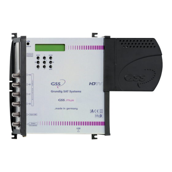
3.2 d e v i C e ov e rv i e w Assembling slots PE connection terminal Display Display contrast control Operating buttons Slot for CA module Micro USB socket (update) SAT tuner inputs A…D Loop through input (LNB) SAT IF output 3.3 C o n n e C t i n g... -
Page 12: If A Free Input Is Available At The Multiswitch
f r e e i n P u t ava i l a b l e t h e m u lt i s w i tC h • Connect the SAT IF output to a free input of the multiswitch. •... - Page 13 —> If you would like to integrate the device to an existing plant, now first you should connect it to the mains and perform all settings (page 21). Therefore especially observe the notes on frequency set- ting (page 19) and level setting (page 20). •...
-
Page 14: Retrofitting A Ca Module
3.4 r Ca e t r o f i t t i n g m o d u l e The device is equipped with a common interface. It allows you to connect a CA module for various scrambling systems and service providers. Scrambled channels can only be descrambled with a CA module suitable for the scram- bling system and the corresponding smart card. -
Page 15: Software
PC and the software "BE-Flash". You can find the current operating software, the software "BE-Flash" and the current assembly instructions on the website "www.gss.de/en". • Unpack the downloaded ".zip file", which contains the new device soft- ware and the "BE-Flash" application. - Page 16 —> In this example – the new added port COM4. • Start the "BE-Flash" application (BEflash.exe) and select the corresponding interface (COM port). • Click on button • Select the .hex file you had unpacked before and click on button •...
- Page 17 —> The update progress is displayed. • Close the "BE-Flash" application. • Uninstall the COM port driver from the device manager after the update is finished successfully! —> Active the COM port driver (in this example COM4). Select in menu Action or via the context menu the menu item Uninstall.
-
Page 18: The Control Panel At A Glance
C o n t r o l P a n e l g l a n C e 4.1 C o n t r o l Pa n e l The key pad on the device is used to scroll through the menus step-by-step: MODE scrolls forward through the menus BACK... -
Page 19: Programming
r o g r a m m i n g 5.1 n ot es f r e q u e n C y s e t t i n g If you fit in the "new" transponder to an existing SAT IF range, you have to set the output frequency to a gap (or the beginning/end) of the spectrum. -
Page 20: Level Too High
5.2 n ot es l e v e l s e t t i n g Equalize the output level of the device (menu "OUTPUT") to the levels of the other transponders, in order not to overdrive downstreamed multiswitches/ amplifiers. e v e l to o h i g h... -
Page 21: Programming Procedure
5.3 P ro g r a m m i n g Pro C e d u r e Bedienhinweise Operating Hints "blättert" Menüs vorwärts scrolls forward through the menu "blättert" Menüs rückwärts scrolls backward through the menu wählen die Eingabeposition select the enter position wählt Untermenü... - Page 22 0x0001 0x0100 DVB-S original original / dejitter DVB-S CA-MODE Data –> CA 204/188 Bit DVB-S DVB-S 01/05 MENU PID Check Vid => Information *) off / Vid / All Page 21 nur mit CA-Modul/ onlywith CA module *) Die angezeigte Information ist abhängig vom verwendeten CA-Modul.
-
Page 23: Programming The Cassette
5.4 P r o g r a m m i n g t h e C a s s e t t e —> Pressing the MODE button for longer than 2 seconds cancels the programming procedure. This takes you back to the "Status menu" from any menu. -
Page 24: Output Parameter, Level
u t P u t Pa r a m e t e r l e v e l In this menu you adjust the output level of the modulator and you have access to the submenus for the modulator configuration. DVB-S OUTPUT –... -
Page 25: Output Symbol Rate, Spectral Position, Code Rate (Fec)
(feC) u t P u t s ym b o l r at e P e C t r a l P os i t i o n C o d e r at e In this menu you can set the symbol rate, the Spectral position and the code rate of the output signal. -
Page 26: Input Parameter
MODE • Press the button. —> The "input parameter" menu – "INPUT" is activated. n P u t Pa r a m e t e r In this menu you select the tuner for which you would like to do the input set- tings in the related submenus. - Page 27 —> The control voltage only serves to control multiswitches and is not suitable for power supply of upstreamed components (maximum load 65mA). —> GSS Multiswitches must be triggered by the following DiSEqC co- mands: Input group A —> DiSEqC command D0 Input group B —>...
-
Page 28: Input Symbol Rate
n P u t s ym b o l r at e In this menu you set the symbol rate of the desired transponder in kSymb/s. SYMBOL 27500 8PSK 2/3 The symbol rates of the satellite transponders can be found in the current chan- nel table of the satellite operator, in various satellite magazines and in the Internet. -
Page 29: Station Selection
• Use </> to position the cursor under the digit of the frequency displayed to be set. • Press +/– to set the respective digit of the input frequency needed. • Repeat the procedure by the quantity of the digits to be set. •... - Page 30 —> The display shows e.g.: A TV + 01/06 Das Erste Meaning of the indicators in the example: "A" Tuner "A" "TV" TV channel type " + " The currently selected station is switched on. "01/06" The 1st of 6 stations is being displayed. "Das Erste"...
-
Page 31: Output Data Rate
—> The "Output data rate" – "DATARATE" main menu is activated. u t P u t data r at e This menu shows the output data rate defined by the output parameter settings and the current needed output data rate in MBit/s. DVB-S DATARATE OVER... -
Page 32: Pcr Jitter
• Use the </> buttons to position the cursor under the digit of the hexadecimal number of the TS-ID to be set. • Press +/– to set the respective digit of the hexadecimal number. • Repeat the procedure by the quantity of the digits to be set. •... -
Page 33: Pid Monitoring
• Use +/– buttons to set the size of the data packets (188/204 Bit). —> AlphaCrypt modules use 204 bit datapackets, Neotion modules 188 bit. • Press the MODE button. –> The "PID monitoring" – "CA" main menu is activated. Pid m o n i to r i n g In this menu you can switch off the PID monitoring and call up a menu for the... - Page 34 m o d u l e The menu varies according to which CA module you are using. For this rea- son, please refer to the operating manual of your particular CA module. The relevant information is shown in the display of the device. This may appear as a fixed display or as scrolling text according to display capabilities.
-
Page 35: Factory Reset
aC to ry r es e t In this menu you can reset all settings to the factory defaults. DVB-S FACTORY DVB-S FACTORY Defaults => STORE => S • Press the > button. —> The factory defaults are invoked. —> By pressing the MODE button, you will be returned to the menu item "Output settings"... - Page 36 Declaration of CE conformity Service: Phone: +49 (0) 911 / 703 2221 • Fax: +49 (0) 911 / 703 2326 • Email: service@gss.de Grundig SAT Systems GmbH • Beuthener Straße 43 • D-90471 Nürnberg • Germany Alterations reserved. Technical data E. & O.E.
Need help?
Do you have a question about the GSS.mux SMCIP 401 and is the answer not in the manual?
Questions and answers