
Related Manuals for Photon Focus MV1-D3360-160-CL Series


Summary of Contents for Photon Focus MV1-D3360-160-CL Series
- Page 1 Photonfocus MV1-D3360-160-CL Camera Series CMOS camera with CameraLink® interface MAN070 03/2015 V1.0...
- Page 2 All information provided in this manual is believed to be accurate and reliable. No responsibility is assumed by Photonfocus AG for its use. Photonfocus AG reserves the right to make changes to this information without notice. Reproduction of this manual in whole or in part, by any means, is prohibited without prior permission having been obtained from Photonfocus AG.
-
Page 3: Table Of Contents
Contents 1 Preface 1.1 About Photonfocus ........1.2 Contact . - Page 4 CONTENTS 5.5.2 Calibration of the Bad Pixel Correction ..... . 46 5.5.3 Storing the calibration in permanent memory ....47 5.6 Column FPN Correction .
- Page 5 9 Mechanical Considerations 9.1 Mechanical Interface ........91 ®...
- Page 6 CONTENTS...
-
Page 7: Preface
Preface 1.1 About Photonfocus The Swiss company Photonfocus is one of the leading specialists in the development of CMOS image sensors and corresponding industrial cameras for machine vision. Photonfocus is dedicated to making the latest generation of CMOS technology commercially available. -
Page 8: Legend
1 Preface Reproduction of this manual in whole or in part, by any means, is prohibited without prior permission having been obtained from Photonfocus AG. Photonfocus can not be held responsible for any technical or typographical er- rors. 1.5 Legend In this documentation the reader’s attention is drawn to the following icons: Important note Alerts and additional information... -
Page 9: Introduction
Introduction ® This manual describes standard Photonfocus D3360 series cameras that have a CameraLink interface. The cameras contain CMV8000 sensor from CMOSIS. The Photonfocus D3360 ® CameraLink series has the following sensor types: Monochrome Standard monochrome sensor Color Color sensor 2.1 Camera Naming convention The naming convention of the D3360 camera series is summarized in Fig. - Page 10 2 Introduction D-camera Cameras that don’t have a line scan mode. These cameras have Prefix2="D" (see also Fig. 2.1). D-xxx D-cameras with camera speed = xxx, e.g. D-160. Color Cameras that have a color sensor. Name Resolution Camera Family Abbreviation Color MV1-D3360-160-CL-10 8 MPix...
-
Page 11: How To Get Started (Cameralink ® )
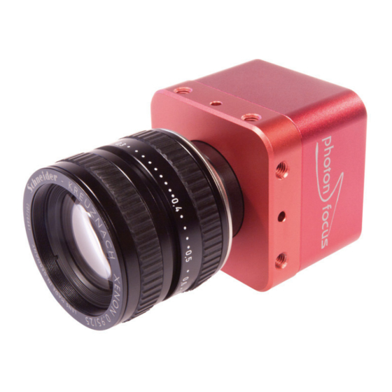
® How to get started (CameraLink ® The following items are required to operate your Photonfocus D3360 CameraLink camera: • ® • Suitable CameraLink frame grabber card to be installed in the PC. All Photonfocus ® ® CameraLink cameras are fully compatible with the CameraLink standard 1.1 and later. - Page 12 ® 3 How to get started (CameraLink Figure 3.1: Camera with protective cap and lens. To choose a lens, see the Lens Finder in the ’Support’ area at www.photonfocus.com. ® Connect the camera to the frame grabber with a suitable CameraLink cable (see Fig.
- Page 13 Check the correct supply voltage and polarity! Do not exceed the maximum operating voltage of +12V DC (± 10%). Connect the power supply to the camera (see Fig. 3.2). The status LED on the rear of the camera will light red for a short moment, and ✎...
- Page 14 ® 3 How to get started (CameraLink 11. Check the status LED on the rear of the camera. The status LED lights green when an image is being produced, and it is red when ✎ serial communication is active. For more information see Section 6.1.4. 12.
-
Page 15: Product Specification 4.1 Introduction
Product Specification 4.1 Introduction The Photonfocus D3360 CMOS camera series is built around the CMOS image sensor CMV8000 from CMOSIS, that provide a resolution of 3360 x 2496 pixels. The cameras are optimized for low light conditions and there are standard monochrome and color (C) models. The cameras are aimed at standard applications in industrial image processing where high sensitivity and high frame rates are required. -
Page 16: Feature Overview
4 Product Specification 4.2 Feature Overview The general specification and features of the camera are listed in the following sections. The detailed description of the camera features is given in Chapter 5. ® Characteristics Photonfocus D3360 CameraLink Series ® Interface CameraLink base configuration Camera Control... - Page 17 Figure 4.1: Photonfocus D3360 CMOS camera series with C-mount lens. 4.2 Feature Overview...
-
Page 18: Available Camera Models
4 Product Specification 4.3 Available Camera Models Please check the availability of a specific camera model on our website www.photonfocus.com. Name Resolution Color Availability MV1-D3360-160-CL-10 3360 x 2496 17 fps released MV1-D3360C-160-CL-10 3360 x 2496 17 fps on request Table 4.2: Available Photonfocus D3360 camera models (Footnotes: frame rate at at full resolution) -
Page 19: Technical Specification
4.4 Technical Specification D-160 Sensor CMOSIS CMV8000 Technology CMOS active pixel Scanning system progressive scan Optical format / diagonal 4/3” (23.02 mm diagonal) Resolution 3360 x 2496 pixels Pixel size 5.5 µm x 5.5 µm Active optical area 18.48 mm x 13.73 mm Full well capacity ~10 ke Spectral range standard sensor... - Page 20 4 Product Specification ® Photonfocus D3360 CameraLink Series Operating temperature / moisture 0°C ... 50°C / 20 ... 80 % Storage temperature / moisture -25°C ... 60°C / 20 ... 95 % Camera power supply +12 V DC (± 10 %) Trigger signal input range +5 ..
- Page 21 Fig. 4.3 shows the quantum efficiency curve of the color CMV8000 sensor from CMOSIS used in the Photonfocus D3360 color cameras. Figure 4.3: Spectral response of the CMV8000 CMOS color image sensors (with micro lenses) The cover glass of the CMV8000 image sensors is plain D263 glass with a transmittance as shown in Fig.
-
Page 22: Rgb Bayer Pattern Filter
4 Product Specification The color cameras are equipped with a infra-red cut-off filter to avoid false colors arising when an infra-red component is present in the illumination. Fig. 4.5 shows the transmssion curve of the cut-off filter. Figure 4.5: Transmission curve of the cut-off filter in the Photonfocus D3360 color camera models 4.5 RGB Bayer Pattern Filter Fig. -
Page 23: Frame Grabber Relevant Configuration
4.6 Frame Grabber relevant Configuration The parameters and settings, which are essential to configure the frame grabber are shown in Table 4.5. D-160 Pixel Clock 80 MHz Number of Taps Greyscale resolution 10 bit / 8 bit EXSYNC not used not used not used Maximal average data rate... - Page 24 4 Product Specification...
-
Page 25: Functionality
Functionality This chapter serves as an overview of the camera configuration modes and explains camera features. The goal is to describe what can be done with the camera. The setup of the cameras is explained in later chapters. 5.1 Reduction of Image Size With the Photonfocus D3360 camera series there are several possibilities to focus on the interesting parts of an image, thus reducing the data rate and increasing the frame rate. - Page 26 5 Functionality F r a m e R a t e w i t h H = 2 4 9 6 . r a m e R a t e [ f p s ] & 6 9 . 4 f p s M V 1 - D 3 3 6 0 ( C ) - 1 6 0 "...
-
Page 27: Multiple Regions Of Interest
5.1.2 Multiple Regions of Interest The Photonfocus D3360 camera series can handle up to 8 different regions of interest. This feature can be used to reduce the amount image data and increase the frame rate. An application example for using multiple regions of interest (MROI) is a laser triangulation system with several laser lines. - Page 28 5 Functionality R O I . X R O I . X R O I . W ( 0 , 0 ) R O I . W ( 0 , 0 ) R O I . Y M R O I 0 . Y M R O I 0 R O I M R O I 1 .
- Page 29 Fig. 5.4 shows an example from hyperspectral imaging where the presence of spectral lines at known regions need to be inspected. By using a MROI only a 636x54 region need to be readout and a frame rate of 5598 fps can be achieved. Without using MROI the resulting frame rate would be 338 fps for a 636x1088 ROI.
-
Page 30: Decimation (Monochrome Cameras)
5 Functionality 5.1.3 Decimation (monochrome cameras) Decimation reduces the number of pixels in y-direction. Decimation in y-direction transfers every n row only and directly results in reduced read-out time and higher frame rate respectively. Decimation can also be used together with ROI or MROI. In this case every ROI should have a height that is a multiple of the decimation setting. - Page 31 0 , 0 ) R O I m a x m a x Figure 5.6: Decimation and ROI ( 0 , 0 ) R O I M R O I 0 M R O I 1 M R O I 2 m a x m a x Figure 5.7: Decimation and MROI...
- Page 32 5 Functionality The image in Fig. 5.8 on the right-hand side shows the result of decimation 3 of the image on the left-hand side. Figure 5.8: Image example of decimation 3 An example of a high-speed measurement of the elongation of an injection needle is given in Fig.
-
Page 33: Decimation (Color Cameras)
5.1.4 Decimation (color cameras) Decimation reduces the number of pixels in y-direction by skipping rows. Decimation in color cameras is slightly different from the monochrome cameras, because the order of the Bayer pattern must be maintained. Beginning from the first row, always two rows are read out and then an even number of rows is skipped. -
Page 34: Maximal Frame Rate
5 Functionality 5.1.5 Maximal Frame Rate The maximal frame rate of the camera depends on the camera settings. The following factors influence the maximal frame rate (see also Table 5.1): • The length of the exposure time: A shorter exposure time can lead to an increase in the maximal frame rate. - Page 35 Simultaneous Read out Timing 1 The exposure time is smaller than the read out time in this timing (see Fig. 5.11). Exposure is started during the sensor read out of the previous frame. The maximal frame rate is in this case (values are given in Table 5.4 and Table 5.5): MaxFrameRate = 1 / (ReadoutTime + TExpDel + TReadoutDel) To avoid a sensor artifact, the exposure must start at a fixed position from the start of the read out of one row.
-
Page 36: Trigger And Strobe
5 Functionality MaxFrameRate = 1 / (ExposureTime + TReadoutDel + ReadoutTime) The ReadoutTime is the height of the ROI multiplied by the read out time of one row (see Table 5.4). F r a m e < n > F r a m e < n + 1 > 6 r i g g e r - x p o s u r e T i m e E x p o s u r e... - Page 37 Interface Trigger In the interface trigger mode, the trigger signal is applied to the camera by ® the CameraLink interface. Fig. 5.14 shows a diagram of the interface trigger setup. The trigger is generated by the frame grabber board and sent on the CC1 signal through the ®...
-
Page 38: Exposure Time Control
5 Functionality M a c h i n e V i s i o n S y s t e m F l a s h T T L + a m e r a 1 C a m e r a L i n k F r a m e G r a b b e r P o w e r D a t a C a m e r a L i n k... -
Page 39: Trigger Delay
A x t e r n a l t r i g g e r p u l s e i n p u t t r i g g e r a f t e r i s o l a t o r d - i s o - i n p u t t r i g g e r p u l s e i n t e r n a l c a m e r a c o n t r o l j i t t e r... -
Page 40: Burst Trigger
5 Functionality A x t e r n a l t r i g g e r p u l s e i n p u t e x p o s u r e t r i g g e r a f t e r i s o l a t o r d - i s o - i n p u t t r i g g e r p u l s e r i s i n g e d g e c a m e r a c o n t r o l j i t t e r... - Page 41 A x t e r n a l t r i g g e r p u l s e i n p u t t r i g g e r a f t e r i s o l a t o r d - i s o - i n p u t t r i g g e r p u l s e i n t e r n a l c a m e r a c o n t r o l j i t t e r...
-
Page 42: Trigger Timing Values
5 Functionality 5.2.6 Trigger timing values Table 5.6 shows the values of the trigger timing parameters. D-160 D-160 Timing Parameter Minimum Maximum 45 ns 60 ns d iso input 25 ns jitter 0.42 s trigger delay 0.42 s burst trigger delay depends on camera settings 0.42 s burst period time... -
Page 43: Software Trigger
5.2.7 Software Trigger The software trigger enables to emulate an external trigger pulse by the camera software through the serial data interface. It works with both burst mode enabled and disabled. As soon as it is performed via the camera software, it will start the image acquisition(s), depending on the usage of the burst mode and the burst configuration. -
Page 44: Strobe Output
5 Functionality Counter reset by an external signal is important if you would like to synchronize multiple cameras. One signal is applied to all cameras which resets the coun- ters simultaneously. The timestamps of all cameras are then theoretically syn- chronous with each other. -
Page 45: Multiple Slope Mode (High Dynamic Range)
Multiple Slope Mode (High Dynamic Range) The Multiple Slope High Dynamic Range (HDR) mode is a special integration mode that increases the dynamic range of the pixels, and thus avoids the saturation of the pixels in many cases. The multiple slope mode is also called multiple slope mode or piecewise linear mode. The multiple slope mode clips illuminated pixels which reach a programmable voltage, while leaving the darker pixels untouched (see Fig. - Page 46 5 Functionality P i x e l r e s e t V h i g h K n e e p o i n t A V l o w 2 ( M u l t i s l o p e _ V a l u e 2 ) K n e e p o i n t B V l o w 1 ( M u l t i s l o p e _ V a l u e 1 ) J i m e...
-
Page 47: Data Path Overview
5.4 Data Path Overview The data path is the path of the image from the output of the image sensor to the output of the camera. The sequence of blocks is shown in figure Fig. 5.22. 1 m a g e S e n s o r B a d P i x e l C o r r e c t i o n C o l u m n F P N... -
Page 48: Bad Pixel Correction
5 Functionality 5.5 Bad Pixel Correction The Bad Pixel Correction corrects single pixel defects of the image sensor. If a pixel is marked as "bad" (defect) then its value is replaced by the mean of the two neighbouring pixels on the same image row. -
Page 49: Storing The Calibration In Permanent Memory
5.5.3 Storing the calibration in permanent memory After running the calibration procedure (see Section 5.5.2) the calibration values are stored in RAM. When the camera is turned off, their values are lost. To prevent this, the calibration values must be stored in flash memory. This can be done by clicking on the property BadPixelCorrection_SaveToFlash (in category BadPixelCorrection). -
Page 50: Storing The Calibration In Permanent Memory
5 Functionality Check the values of the properties ColCorrection_Overflow and ColCorrection_Underflow. Both should have the value 0 after calibration. If ColCorrection_Overflow is not 0, then decrease BlackLevel (in category AnalogControl) and re-run the procedure from step 6 on. If ColCorrection_Underflow is not 0, then increase BlackLevel (in category AnalogControl) and re-run the procedure from step 6 on. -
Page 51: Grey Level Transformation (Lut)
5.8 Grey Level Transformation (LUT) Grey level transformation is remapping of the grey level values of an input image to new values. The look-up table (LUT) is used to convert the greyscale value of each pixel in an image into another grey value. It is typically used to implement a transfer curve for contrast expansion. -
Page 52: Gain
5 Functionality 5.8.1 Gain The ’Gain’ mode performs a digital, linear amplification with clamping (see Fig. 5.24). It is configurable in the range from 1.0 to 4.0 (e.g. 1.234). Grey level transformation − Gain: y = (255/1023) ⋅ a ⋅ x a = 1.0 a = 2.0 a = 3.0... -
Page 53: Gamma
5.8.2 Gamma The ’Gamma’ mode performs an exponential amplification, configurable in the range from 0.4 to 4.0. Gamma > 1.0 results in an attenuation of the image (see Fig. 5.25), gamma < 1.0 results in an amplification (see Fig. 5.26). Gamma correction is often used for tone mapping and better display of results on monitor screens. -
Page 54: User-Defined Look-Up Table
5 Functionality 5.8.3 User-defined Look-up Table In the ’User’ mode, the mapping of input to output grey levels can be configured arbitrarily by the user. There is an example file in the PFRemote folder. LUT files can easily be generated with a standard spreadsheet tool. - Page 55 ( 0 , 0 ) N N N N O O L U T 0 O L U T 1 O m a x m a x Figure 5.28: Overlapping Region-LUT example ( 0 , 0 )
- Page 56 5 Functionality Fig. 5.30 shows the application of the Region-LUT to a camera image. The original image without image processing is shown on the left-hand side. The result of the application of the Region-LUT is shown on the right-hand side. One Region-LUT was applied on a small region on the lower part of the image where the brightness has been increased.
-
Page 57: Crosshairs
5.9 Crosshairs 5.9.1 Functionality The crosshairs inserts a vertical and horizontal line into the image. The width of these lines is one pixel. The grey level is defined by a 12 bit value (0 means black, 4095 means white). This allows to set any grey level to get the maximum contrast depending on the acquired image. - Page 58 5 Functionality The x- and y-positon is absolute to the sensor pixel matrix. It is independent on the ROI, MROI or decimation configurations. Figure Fig. 5.32 shows two situations of the crosshairs configuration. The same MROI settings is used in both situations. The crosshairs however is set differently.
-
Page 59: Image Information And Status Line
5.10 Image Information and Status Line There are camera properties available that give information about the acquired images, such as an image counter, average image value and the number of missed trigger signals. These properties can be queried by software. Alternatively, a status line within the image data can be switched on that contains all the available image information. - Page 60 5 Functionality Start pixel index Parameter width [bit] Parameter Description Preamble: 0x55AA00FF Image Counter (see Section 5.10.1) Real Time Counter (see Section 5.10.1) Missed Trigger Counter (see Section 5.10.1) Image Average Value("raw" data without taking in account gain settings) (see Section 5.10.1) Integration Time in units of clock cycles (see Table 4.3) Reserved (Burst Trigger Number)
-
Page 61: Camera Type Codes
5.10.3 Camera Type Codes Camera Model Camera Type Code MV1-D3360-160-CL-10 MV1-D3360C-160-CL-10 Table 5.9: Type codes of Photonfocus D3360 camera series 5.10 Image Information and Status Line... -
Page 62: Test Images
5 Functionality 5.11 Test Images Test images are generated in the camera FPGA, independent of the image sensor. They can be used to check the transmission path from the camera to the frame grabber. Independent from the configured grey level resolution, every possible grey level appears the same number of times in a test image. - Page 63 Figure 5.35: LFSR (linear feedback shift register) test image non-flat histogram (Fig. 5.37) indicates problems, that may be caused either by the cable, by the connectors or by the frame grabber. ® A possible origin of failure message can be caused by the CameraLink cable which exceeds the maximum length.
- Page 64 5 Functionality ® Some thinner CameraLink cables have a predefined direction. In these cables not all twisted pairs are separately shielded to meet the RS644 standard. These pairs are used for the transmission of the RX/TX and for the CC1 to CC4 low frequency control signals.
-
Page 65: Configuration Interface (Cameralink )
® 5.12 Configuration Interface (CameraLink ® A CameraLink camera can be controlled by the user via a RS232 compatible asynchronous ® serial interface. This interface is contained within the CameraLink interface as shown in Fig. 5.38 and is physically not directly accessible. Instead, the serial communication is usually routed through the frame grabber. - Page 66 5 Functionality...
-
Page 67: Hardware Interface
Hardware Interface 6.1 Connectors ® 6.1.1 CameraLink Connector ® The CameraLink cameras are interfaced to external components via ® ® • a CameraLink connector, which is defined by the CameraLink standard as a 26 pin, 0.5" Mini Delta-Ribbon (MDR) connector to transmit configuration, image data and trigger. •... -
Page 68: Trigger And Strobe Signals
6 Hardware Interface 6.1.3 Trigger and Strobe Signals The power connector contains an external trigger input and a strobe output. The trigger input is equipped with a constant current diode which limits the current of the optocoupler over a wide range of voltages. Trigger signals can thus directly get connected with the input pin and there is no need for a current limiting resistor, that depends with its value on the input voltage. -
Page 69: Status Indicator (Cameralink ® Cameras)
STROBE_VDD Pull-up Resistor 15 V > 3.9 kOhm 10 V > 2.7 kOhm > 2.2 kOhm > 1.8 kOhm > 1.0 kOhm Table 6.1: Pull-up resistor for strobe output and different voltage levels ® 6.1.4 Status Indicator (CameraLink cameras) A dual-color LED on the back of the camera gives information about the current status of the ®... - Page 70 6 Hardware Interface ® Serial communication: A CameraLink camera can be controlled by the user via a RS232 compatible asynchronous serial interface. This interface is contained within the ® CameraLink interface and is physically not directly accessible. Refer to Section 5.12 for more information.
-
Page 71: The Pfremote Control Tool
The PFRemote Control Tool 7.1 Overview PFRemote is a graphical configuration tool for Photonfocus cameras. The latest release can be downloaded from the support area of www.photonfocus.com. All Photonfocus cameras can be either configured by PFRemote, or they can be programmed with custom software using the PFLib SDK ([PFLIB]). -
Page 72: Installation Notes
7 The PFRemote Control Tool 7.4 Installation Notes Before installing the required software with the PFInstaller, make sure that your frame grabber software is installed correctly. Several DLLs are necessary in order to be able to communicate with the cameras: •... -
Page 73: Ports, Device Initialization
File Menu Clear Log: Clears the log file buffer Quit: Exit the program Help Menu About: Copyright notice and version information Help F1: Invoke the online help (PFRemote documentation) 7.5.2 Ports, Device Initialization After starting PFRemote, the main window as shown in Fig. 7.2 will appear. In the PortBrowser in the upper left corner you will see a list of supported ports. -
Page 74: Main Buttons
7 The PFRemote Control Tool 7.5.3 Main Buttons The buttons on the right side of the configuration dialog store and reset the camera configuration. Figure 7.3: Main buttons Reset: Reset the camera and load the default configuration. Store as defaults: Store the current configuration in the camera flash memory as the default configuration. -
Page 75: Graphical User Interface (Gui)
Graphical User Interface (GUI) 8.1 MV1-D3360-160 This section describes the parameters of the following cameras: • MV1-D3360-160-CL, CameraLink interface • MV1-D3360C-160-CL, CameraLink interface The following sections are grouped according to the tabs in the configuration dialog. Figure 8.1: Frame rate and average value indication Frame Rate [fps]: Shows the actual frame rate of the camera in frames per second. -
Page 76: Exposure
8 Graphical User Interface (GUI) 8.1.1 Exposure This tab contains exposure settings. Figure 8.2: Exposure panel Exposure Exposure time [ms]: Configure the exposure time in milliseconds. Constant Frame Rate: When the Constant Frame Rate (CFR) is switched on, the frame rate (number of frames per second) can be varied from almost 0 up to the maximum frame rate. - Page 77 Rate is enabled. The minimum frame time depends on the exposure time and readout time. Black Level Offset It may be necessary to adjust the black level offset of the camera. Black Level Offset: Black level offset value. Use this to adjust the black level. 8.1 MV1-D3360-160...
-
Page 78: Window
8 Graphical User Interface (GUI) 8.1.2 Window This tab contains the settings for the region of interest. Figure 8.3: Window panel Region of Interest The region of interest (ROI) is defined as a rectangle (X, Y), (W, H) where X: X - coordinate, starting from 0 in the upper left corner. Y: Y - coordinate, starting from 0 in the upper left corner. - Page 79 Window width is only available in steps of 8 pixel. When using ROI in x-direction, enable DataValid (DVAL) feature on the frame grabber. Decimation Decimation reduces the number of pixels in y-direction. Decimation can also be used together with a ROI or MROI. Decimation in y-direction transfers every n-th row only and directly results in reduced read-out time and higher frame rate respectively.
- Page 80 8 Graphical User Interface (GUI) Settings for frame grabber Shows the ROI settings on the camera interface. Use these settings to configure the frame grabber. Wtot: Number of pixels in a line (Width of the image). Htot: Number of lines out of the camera (Height of the image). Update: Update values of Wtot and Htot.
-
Page 81: Trigger
8.1.3 Trigger This tab contains trigger and strobe settings. Figure 8.4: Trigger panel Trigger Trigger Source: Free running: The camera continuously delivers images with a certain configurable frame rate. Interface Trigger: The Trigger signal is applied to the camera by the CameraLink frame grabber or the USB interface respectively. - Page 82 8 Graphical User Interface (GUI) Camera: The exposure time is defined by the property ExposureTime. Trigger Pulse Width: The exposure time is defined by the pulse width of the trigger signal (level-controlled exposure). This property disables Multislope, Burst trigger. Exposure time defined by "Trigger Pulse Width" is also known as Level controlled trigger.
-
Page 83: Data Output
8.1.4 Data Output This tab contains image data settings. Figure 8.5: MV1-D3360-160 data output panel Output Mode Output Mode: Normal: Normal mode. LFSR: Test image. Linear feedback shift register (pseudo-random image). The pattern depends on the grey level resolution. Ramp: Test image. Values of pixel are incremented by 1, starting at each row. The pattern depends on the grey level resolution. - Page 84 8 Graphical User Interface (GUI) Resolution: 8 Bit: Grey level resolution of 8 bit. 10 Bit: Grey level resolution of 10 bit. Digital Gain: 1x: No digital gain, normal mode. 2x: Digital gain 2. 4x: Digital gain 4. 8x: Digital gain 8. Digital Offset: Substracts an offset from the data.
-
Page 85: Lut (Look-Up-Table)
8.1.5 LUT (Look-Up-Table) This tab contains LUT settings. Figure 8.6: LUT panel Grey level transformation is remapping of the grey level values of an input image to new values which transform the image in some way. The look-up-table (LUT) is used to convert the greyscale value of each pixel in an image into another grey value. - Page 86 8 Graphical User Interface (GUI) LUTX Enable LUT X Enable the LUTX Gain: Linear function. Y = 256 / 4096 * value * X; Valid range for value [1...4]. Gamma: Gamma function. Y = 256 / 4096^value * X ^ value; Valid range for value [0.4...4]. value: Enter a value.
-
Page 87: Multislope
8.1.6 Multislope This tab contains Multislope settings. Figure 8.7: Multislope panel Multislope This camera has the possibility to achieve a high optical dynamic range by using a piecewise linear response. This feature will clip illuminated pixels, while leaving the darker pixels untouched.The clipping level can be adjusted 2 times within one exposure time to achieve a maximum of 3 slopes in the response curve. -
Page 88: Correction
8 Graphical User Interface (GUI) 8.1.7 Correction This tab contains Correction settings. Figure 8.8: Correction panel Correction With two different methods its possible to correct the image of the senor. While Bad Pixel Correction only affects a single pixel. Column Correction affects a whole column Column Correction: Due to the readout structure of the image sensors there is a column-wise fixed pattern noise (FPN). - Page 89 If a pixel is marked as "bad" (defect) then its value is replaced by the mean of the two neighbouring pixels on the same image row. 8.1 MV1-D3360-160...
-
Page 90: Info
8 Graphical User Interface (GUI) 8.1.8 Info This panel shows camera specific information such as type code, serial number and firmware revision of the FPGA and microcontroller and the description of the camera interface. Figure 8.9: Info panel Camera Info Camera name: Name of the connected camera. - Page 91 Interface: Description of the camera interface. Baudrate: The actual baud rate between camera and frame grabber. For any support requests, please enclose the information provided on this panel. Counters The camera has the following counters. Image: The image counter is a 24 bit real-time counter and is incremented by 1 for every new image.
- Page 92 8 Graphical User Interface (GUI) Temperature Sensor PCB [deg C]: The temperature of the Sensor PCB. ADC PCB [deg C]: The temperature of the Processor PCB. Update: Press this button to update all temperature values.
-
Page 93: Mechanical Considerations
Mechanical Considerations 9.1 Mechanical Interface During storage and transport, the camera should be protected against vibration, shock, moisture and dust. The original packaging protects the camera adequately from vibration and shock during storage and transport. Please either retain this packaging for possible later use or dispose of it according to local regulations. - Page 94 9 Mechanical Considerations...
-
Page 95: Warranty
Warranty The manufacturer alone reserves the right to recognize warranty claims. 10.1 Warranty Terms The manufacturer warrants to distributor and end customer that for a period of two years from the date of the shipment from manufacturer or distributor to end customer (the "Warranty Period") that: •... - Page 96 10 Warranty...
-
Page 97: References
References All referenced documents can be downloaded from our website at www.photonfocus.com. ® CL CameraLink Specification, January 2004... - Page 98 11 References...
-
Page 99: A Pinouts
Pinouts A.1 Power Supply Connector The power supply plugs are available from Binder connectors at www.binder-connector.de. Fig. A.2 shows the power supply plug from the solder side. The pin assignment of the power supply plug is given in Table A.2. It is extremely important that you apply the appropriate voltages to your camera. - Page 100 A Pinouts " Figure A.2: Power supply plug, 7-pole (rear view of plug, solder side) I/O Type Name Description +12 V DC (± 10%) Ground RESERVED Do not connect STROBE-VDD +5 .. +15 V DC STROBE Strobe control (opto-isolated) TRIGGER External trigger (opto-isolated), +5 ..
-
Page 101: Cameralink ® Connector
Name Description SHIELD Shield ® N_XD0 Negative LVDS Output, CameraLink Data D0 ® N_XD1 Negative LVDS Output, CameraLink Data D1 ® N_XD2 Negative LVDS Output, CameraLink Data D2 ® N_XCLK Negative LVDS Output, CameraLink Clock ® N_XD3 Negative LVDS Output, CameraLink Data D3 P_SERTOCAM Positive LVDS Input, Serial Communication to the camera... - Page 102 A Pinouts...
-
Page 103: B Camera Revisions
Camera Revisions B.1 General Remarks This chapter lists differences between the revisions of the camera models. -
Page 104: 8Mp Area Scan Cameras
B Camera Revisions B.2 8MP Area Scan Cameras Table B.1 shows revision information for the following models: D160 MV1-D3360-160-CL-10 C160 MV1-D3360C-160-CL-10 D160 V1.0 C160 V1.0 MROI Decimation Standard Trigger Multiple Slope Bad Pixel Correction Column FPN Correction Digital Gain / Offset Analog Gain Crosshairs Status Line... -
Page 105: C Revision History
Revision History Revision Date Changes March 2016 First version...
Need help?
Do you have a question about the MV1-D3360-160-CL Series and is the answer not in the manual?
Questions and answers