
Related Manuals for Photon Focus MV1-D1280-L01-1280-G2-12


Summary of Contents for Photon Focus MV1-D1280-L01-1280-G2-12
- Page 1 Photonfocus MV1-D1280-L01 Camera Series CMOS camera with GigE interface MAN077 11/2017 V1.0...
- Page 2 All information provided in this manual is believed to be accurate and reliable. No responsibility is assumed by Photonfocus AG for its use. Photonfocus AG reserves the right to make changes to this information without notice. Reproduction of this manual in whole or in part, by any means, is prohibited without prior permission having been obtained from Photonfocus AG.
-
Page 3: Table Of Contents
Contents 1 Preface 1.1 IMPORTANT NOTICE! ........1.2 About Photonfocus . - Page 4 CONTENTS 5.2.4 Exposure Time Control ....... . 52 5.2.5 Trigger Delay ........53 5.2.6 Strobe Output .
- Page 5 CONTENTS 7.8 PLC connections ........103 8 Software 8.1 Software for Photonfocus GigE Cameras .
- Page 6 CONTENTS 12 Support and Repair 12.1 Technical Support ........129 12.2 Repair and obtaining an RMA Number .
-
Page 7: Preface
Preface 1.1 IMPORTANT NOTICE! READ THE INSTRUCTIONS FOR USE BEFORE OPERATING THE CAMERA STORE THE INSTRUCTIONS FOR USE FOR FURTHER READING Photonfocus AG Bahnhofplatz 10 CH-8853 Lachen SZ Switzerland www.photonfocus.com info@photonfocus.com +41 – 55 451 00 00 MAN077 11/2017 V1.0 7 of 139... -
Page 8: About Photonfocus
1 Preface 1.2 About Photonfocus The Swiss company Photonfocus is one of the leading specialists in the development of CMOS image sensors and corresponding industrial cameras for machine vision. Photonfocus is dedicated to making the latest generation of CMOS technology commercially available. -
Page 9: Legend
1.6 Legend 1.6 Legend In this documentation the reader’s attention is drawn to the following icons: Important note, additional information Important instructions General warning, possible component damage hazard Warning, electric shock hazard Warning, fire hazard MAN077 11/2017 V1.0 9 of 139... - Page 10 1 Preface MAN077 11/2017 V1.0 10 of 139...
-
Page 11: Introduction
Introduction This manual describes standard Photonfocus Luxima series cameras that have a Gigabit Ethernet (GigE) interface. The cameras contain LUX1310 sensors from Luxima. The Photonfocus Luxima GigE series has the following camera model families: D-cameras Standard digital area scan cameras. There are camera models in every camera family with the following sensor types: Monochrome Standard monochrome sensor Color Color sensor... - Page 12 2 Introduction Name Resolution Camera Family Abbreviation Color MV1-D1280-L01-1280-G2-12 1.3 MPix D-camera D-1280 Table 2.1: Camera models covered by this manual MAN077 11/2017 V1.0 12 of 139...
-
Page 13: How To Get Started (Gige G2)
How to get started (GigE G2) 3.1 Introduction This guide shows you: • How to install the required hardware (see Section 3.2) • How to install the required software (see Section 3.3) and configure the Network Adapter Card (see Section 3.4 and Section 3.5) •... - Page 14 3 How to get started (GigE G2) Remove the Photonfocus GigE camera from its packaging. Please make sure the following items are included with your camera: • Power supply connector • Camera body cap If any items are missing or damaged, please contact your dealership. Connect the camera to the GigE interface of your PC with a shielded GigE cable of at least Cat 5E or 6.
-
Page 15: Software Installation
3.3 Software Installation 3.3 Software Installation This section describes the installation of the required software to accomplish the tasks described in this chapter. Install the latest drivers for your GigE network interface card. Download the latest eBUS SDK installation file from the Photonfocus server. You can find the latest version of the eBUS SDK on the support (Software Down- load) page at www.photonfocus.com. - Page 16 3 How to get started (GigE G2) Figure 3.3: PFInstaller components choice MAN077 11/2017 V1.0 16 of 139...
-
Page 17: Network Adapter Configuration
3.4 Network Adapter Configuration 3.4 Network Adapter Configuration This section describes recommended network adapter card (NIC) settings that enhance the performance for GigEVision. Additional tool-specific settings are described in the tool chapter. Open the Network Connections window (Control Panel -> Network and Internet Connections ->... - Page 18 3 How to get started (GigE G2) By default, Photonfocus GigE Vision cameras are configured to obtain an IP address automatically. For this quick start guide it is recommended to configure the network adapter to obtain an IP address automatically. To do this, select Internet Protocol (TCP/IP) (see Fig.
- Page 19 3.4 Network Adapter Configuration Open again the Local Area Connection Properties window (see Fig. 3.4) and click on the Configure button. In the window that appears click on the Advanced tab and click on Jumbo Frames in the Settings list (see Fig. 3.6). The highest number gives the best performance. Some tools however don’t support the value 16128.
- Page 20 3 How to get started (GigE G2) No firewall should be active on the network adapter where the Photonfocus GigE camera is connected. If the Windows Firewall is used then it can be switched off like this: Open the Windows Firewall configuration (Start -> Control Panel -> Network and Internet Connections ->...
-
Page 21: Network Adapter Configuration For Pleora Ebus Sdk
3.5 Network Adapter Configuration for Pleora eBUS SDK 3.5 Network Adapter Configuration for Pleora eBUS SDK Open the Network Connections window (Control Panel -> Network and Internet Connections -> Network Connections), right click on the name of the network adapter where the Photonfocus camera is connected and select Properties from the drop down menu that appears. -
Page 22: Getting Started
3 How to get started (GigE G2) 3.6 Getting started This section describes how to acquire images from the camera and how to modify camera settings. Open the PF_GEVPlayer software (Start -> All Programs -> Photonfocus -> GigE_Tools -> PF_GEVPlayer) which is a GUI to set camera parameters and to see the grabbed images (see Fig. - Page 23 3.6 Getting started Click on the Select / Connect button in the PF_GEVPlayer . A window with all detected devices appears (see Fig. 3.10). If your camera is not listed then select the box Show unreachable GigE Vision Devices. Figure 3.10: GEV Device Selection Procedure displaying the selected camera Select camera model to configure and click on Set IP Address..
- Page 24 3 How to get started (GigE G2) Select a valid IP address for selected camera (see Fig. 3.12). There should be no exclamation mark on the right side of the IP address. Click on Ok in the Set IP Address dialog.
- Page 25 3.6 Getting started If no images can be grabbed, close the PF_GEVPlayer and adjust the Jumbo Frame parameter (see Section 3.3) to a lower value and try again. Figure 3.14: PF_GEVPlayer displaying live image stream Check the status LED on the rear of the camera. The status LED light is green when an image is being acquired, and it is red when serial communication is active.
- Page 26 3 How to get started (GigE G2) To modify the exposure time scroll down to the AcquisitionControl control category (bold title) and modify the value of the ExposureTime property. MAN077 11/2017 V1.0 26 of 139...
-
Page 27: Product Specification
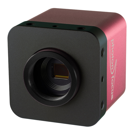
Product Specification 4.1 Introduction The Photonfocus Luxima GigE camera series is built around the CMOS image sensor LUX1310 from Luxima, that provides a resolution of 1280 x 1024. The camera series is optimized for low light conditions. The cameras are aimed at sophisticated applications in industrial image processing where high sensitivity and high frame rates are required. - Page 28 4 Product Specification Figure 4.1: Photonfocus Luxima GigE camera series with C-mount lens. 28 of 139 MAN077 11/2017 V1.0...
-
Page 29: Feature Overview
4.2 Feature Overview 4.2 Feature Overview The general specification and features of the camera are listed in the following sections. The detailed description of the camera features is given in Chapter 5. Characteristics Photonfocus Luxima GigE Camera Series Interface Gigabit Ethernet, GigE Vision and GenICam compliant Camera Control GigE Vision Suite Trigger Modes... -
Page 30: Available Camera Models
4 Product Specification 4.3 Available Camera Models Please check the availability of a specific camera model on our website www.photonfocus.com. Name Resolution MV1-D1280-L01-1280-G2-12 1280 x 1024 85 fps / 948 fps Table 4.2: Available Photonfocus Luxima GigE camera models (Footnotes: streaming mode,... -
Page 31: Technical Specification
4.4 Technical Specification 4.4 Technical Specification MV1-D1280-L01-1280 Sensor Luxima Technology LUX1310 Technology CMOS active pixel Scanning system progressive scan Optical format / diagonal 2/3” (10.82 mm diagonal) Sensor resolution 1280 x 1024 pixels Pixel size 6.6 m x 6.6 m Active optical area 8.45 mm x 6.76 mm Full well capacity... -
Page 32: Heat Dissipation
4 Product Specification MV1-D1280-L01-1280 Operating temperature / moisture 0°C ... 40°C / 20 ... 80 % Storage temperature / moisture -25°C ... 60°C / 20 ... 95 % Operating height <2000 m above sea level Camera power supply +12 V DC (- 10 %) ... +24 V DC (+ 10 %) Trigger signal input range +5 .. -
Page 33: Absolute Maximum Ratings
4.4 Technical Specification 4.4.2 Absolute Maximum Ratings Parameter Value Power Supply Voltage 26.4 V ESD Contact Discharge Power Supply 4 kV ESD Air Discharge Power Supply 8 kV Fast Transients/Bursts Power Supply 2 kV Camera Control Input Signal Voltage Single Ended -30 V ... -
Page 34: Electrical Characteristics
4 Product Specification 4.4.3 Electrical Characteristics Parameter Value Camera Power Supply +12 V (-10%) ... +24 V (+10%) Camera Control Input Single Ended +5 V ... +30 V Camera Control Input RS422 Receiver Sensitivity +/- 200 mV Camera Control Input RS422 Maximum Common Mode Range -7 V ... -
Page 35: Functionality
Functionality This chapter serves as an overview of the camera configuration modes and explains camera features. The goal is to describe what can be done with the camera. The setup of the cameras is explained in later chapters. 5.1 Reduction of Image Size With Photonfocus cameras there are several possibilities to focus on the interesting parts of an image, thus reducing the data rate and increasing the frame rate. -
Page 36: Multiple Regions Of Interest
5 Functionality 5.1.2 Multiple Regions of Interest The Photonfocus Luxima GigE camera series can handle up to 8 different regions of interest. This feature can be used to reduce the amount of image data and increase the frame rate. An application example for using multiple regions of interest (MROI) is a laser triangulation system with several laser lines. - Page 37 5.1 Reduction of Image Size R O I . X R O I . X R O I . W ( 0 , 0 ) R O I . W ( 0 , 0 ) R O I . Y M R O I 0 .
- Page 38 5 Functionality Fig. 5.3 shows an example from hyperspectral imaging where the presence of spectral lines at known regions need to be inspected. By using a MROI only a 640x54 region need to be readout and a frame rate of 3160 fps can be achieved. Without using MROI the resulting frame rate would be for a 640x1024 ROI 170 fps.
-
Page 39: Decimation (Monochrome Cameras)
5.1 Reduction of Image Size 5.1.3 Decimation (monochrome cameras) Decimation reduces the number of pixels in y-direction. Decimation in y-direction transfers every n row only and directly results in reduced read-out time and higher frame rate respectively. Decimation can also be used together with ROI or MROI. In this case every ROI should have a height that is a multiple of the decimation setting. - Page 40 5 Functionality 0 , 0 ) R O I m a x m a x Figure 5.5: Decimation and ROI ( 0 , 0 ) R O I M R O I 0 M R O I 1 M R O I 2 m a x m a x Figure 5.6: Decimation and MROI...
- Page 41 5.1 Reduction of Image Size The image in Fig. 5.7 on the right-hand side shows the result of decimation 3 of the image on the left-hand side. Figure 5.7: Image example of decimation 3 An example of a high-speed measurement of the elongation of an injection needle is given in Fig.
-
Page 42: Roi Elements
5 Functionality 5.1.4 ROI Elements In some cases only some parts of the image need to be observed. The ROI element feature allows the definition of up to 256 individual small regions - which are called elements - all over the sensor area. -
Page 43: Binning (Fpga)
5.1 Reduction of Image Size Usage The ROI element feature can be enabled as soons as it has been configured properly. The configuration must be done according to the following procedure: The element height and width must be set, which is applied globally for all elements in the image. - Page 44 5 Functionality Figure 5.10: ROI element configuration mode Fig. 5.11 shows a schematic of 2x2 binning: pixels in a 2x2 neighbourhood (displayed as pixels with the same color in the schematic) are binned together: their intensity values are summed and divided by four. The output image has half the height and half the width of the input image.
- Page 45 5.1 Reduction of Image Size O u t p u t I m a g e 5 e n s o r I m a g e Figure 5.11: Example of 2x2 binning Property Type Description BinningHorizontal Integer Number of pixels combined in binning in horizontal direction.
-
Page 46: Maximal Frame Rate
5 Functionality 5.1.6 Maximal Frame Rate The maximal frame rate of the camera depends on the camera settings. The following factors influence the maximal frame rate (see also Table 5.1): • The length of the exposure time: A shorter exposure time can lead to an increase in the maximal frame rate. -
Page 47: Frame Combine
5.1 Reduction of Image Size F r a m e < n > F r a m e < n + 1 > 6 r i g g e r - x p o s u r e T i m e E x p o s u r e R e a d o u t R e a d o u t T i m e... -
Page 48: Trigger And Strobe
5 Functionality There exist possibilities to transmit the combined frame even if there is not enough data to fill FrameCombine_Timeout A timeout can be specified after which the combined frame will be transmitted, regardless if there was enough data to fill it. The timeout counter is reset after each frame and counts until a new trigger has been detected or until the timeout is reached. -
Page 49: Trigger Source
5.2 Trigger and Strobe 5.2.2 Trigger Source The trigger signal can be configured to be active high or active low by the TriggerActivation (category AcquisitionControl) property. One of the following trigger sources can be used: Free running The trigger is generated internally by the camera. Exposure starts immediately after the camera is ready and the maximal possible frame rate is attained, if AcquisitionFrameRateEnable is disabled. - Page 50 5 Functionality Figure 5.14: Trigger source Figure 5.15: Trigger Inputs - Multiple GigE solution MAN077 11/2017 V1.0 50 of 139...
- Page 51 5.2 Trigger and Strobe AcquisitionMode After the command AcquisitionStart is executed: Continuous Camera aquires image frames continuously. Acquisition can be stopped by executing AcquisitionStop command. SingleFrame Camera acquires one frame and acquisition stops. MultiFrame Camera acquires n=AcquisitionFrameCount frames and acquisition stops.
-
Page 52: Exposure Time Control
5 Functionality 5.2.4 Exposure Time Control Depending on the trigger mode, the exposure time can be determined either by the camera or by the trigger signal itself: Camera-controlled Exposure time In this trigger mode the exposure time is defined by the camera. -
Page 53: Trigger Delay
5.2 Trigger and Strobe results then from the synchronous design of the FPGA state machines and from to trigger offset requirement to start an exposure at a fixed point from the start of the read out of a row. The exposure time t is controlled with an internal exposure time controller. - Page 54 5 Functionality A x t e r n a l t r i g g e r p u l s e i n p u t t r i g g e r a f t e r i s o l a t o r d - i s o - i n p u t t r i g g e r p u l s e i n t e r n a l c a m e r a c o n t r o l j i t t e r...
-
Page 55: Trigger Timing Values
5.2 Trigger and Strobe 5.2.8 Trigger Timing Values Table 5.4 shows the values of the trigger timing parameters. Timing Parameter Minimum Maximum 1.5 s d iso input 65 ns 185 ns d RS422 input 25 ns jitter 0.42 s trigger delay 0.42 s burst trigger delay depends on camera settings... -
Page 56: A/B Trigger For Incremental Encoder
5 Functionality 5.2.9 A/B Trigger for Incremental Encoder An incremental encoder with A/B outputs can be used to synchronize the camera triggers to the speed of a conveyor belt. These A/B outputs can be directly connected to the camera and appropriate triggers are generated inside the camera. - Page 57 5.2 Trigger and Strobe There is a bug in the single A/B trigger mode in some camera revisions (see Ap- pendix B). In this case when the encoder position moves back and forth by a small amount, the EncoderCounter is incremented and the decrement is some- times omitted, leading to a wrong EncoderPosition indication in the camera.
- Page 58 5 Functionality A/B Trigger Debounce A debouncing logic can be enabled by setting ABTriggerDeBounce=True. It is implemented with a watermark value of the EncoderCounter (see Fig. 5.21). Suppose ABTriggerDirection=fwd, then the watermark value is increased with the increments of the EncoderCounter. If EncoderCounter decreases, e.g.
- Page 59 5.2 Trigger and Strobe A/B Trigger Divider if ABTriggerDivider>1 then not all internally generated triggers are applied to the camera logic. E.g. If ABTriggerDivider=2, then every second trigger is applied to the camera (see Fig. 5.23). G r a y C o u n t e r E n c o d e r C o u n t e r I n t e r n a l T r i g g e r F w d A p p l i e d T r i g g e r F w d...
-
Page 60: Missed Trigger Counters
5 Functionality By default the Encoder Position is only generated when TriggerMode=On and TriggerSource=ABTrigger. When the property ABTriggerCountAlways=True, then the Encoder Position is generated regardless of the trigger mode. 5.2.10 Missed Trigger Counters The missed trigger counters are important tools to make sure that the frequency of an external trigger can be processed by the camera. - Page 61 5.2 Trigger and Strobe The setting Counter_ResetCounterMode=Continuous resets the counters on every occurrence of an active edge of the reset source without the requirement to arm the device first. This setting is suited if the reset source signal is different than the camera trigger. The active edge of the reset input can be set by the property Counter_ResetCounterSourceInvert.
-
Page 62: Multiple Slope Mode (High Dynamic Range)
5 Functionality Multiple Slope Mode (High Dynamic Range) The Multiple Slope High Dynamic Range (HDR) mode is a special integration mode that increases the dynamic range of the pixels, and thus avoids the saturation of the pixels in many cases. The multiple slope mode is also called multiple slope mode or piecewise linear mode. The multiple slope mode clips illuminated pixels which reach a programmable voltage, while leaving the darker pixels untouched (see Fig. - Page 63 5.3 Multiple Slope Mode (High Dynamic Range) P i x e l r e s e t V h i g h K n e e p o i n t A V l o w 2 ( M u l t i s l o p e _ V a l u e 2 ) K n e e p o i n t B V l o w 1 ( M u l t i s l o p e _ V a l u e 1 ) J i m e...
-
Page 64: Data Path Overview
5 Functionality 5.4 Data Path Overview The data path is the path of the image from the output of the image sensor to the output of the camera. The sequence of blocks is shown in figure Fig. 5.28. I m a g e S e n s o r * a d P i x e l C o r r e c t i o n C o l u m n F P N... -
Page 65: Bad Pixel Correction
5.5 Bad Pixel Correction 5.5 Bad Pixel Correction The Bad Pixel Correction corrects single pixel defects of the image sensor. If a pixel is marked as "bad" (defect) then its value is replaced by the mean of the two neighbouring pixels on the same image row. -
Page 66: Storing The Calibration In Permanent Memory
5 Functionality 5.5.3 Storing the calibration in permanent memory After running the calibration procedure (see Section 5.5.2) the calibration values are stored in RAM. When the camera is turned off, their values are lost. To prevent this, the calibration values must be stored in flash memory. This can be done by clicking on the property BadPixelCorrection_SaveToFlash (in category BadPixelCorrection). -
Page 67: Storing The Calibration In Permanent Memory
5.7 Gain and Offset Check the values of the properties ColCorrection_Overflow and ColCorrection_Underflow. Both should have the value 0 after calibration. If ColCorrection_Overflow is not 0, then decrease BlackLevel (in category AnalogControl) and re-run the procedure from step 6 on. If ColCorrection_Underflow is not 0, then increase BlackLevel (in category AnalogControl) and re-run the procedure from step 6 on. -
Page 68: Grey Level Transformation (Lut)
5 Functionality 5.8 Grey Level Transformation (LUT) Grey level transformation is remapping of the grey level values of an input image to new values. The look-up table (LUT) is used to convert the greyscale value of each pixel in an image into another grey value. - Page 69 5.8 Grey Level Transformation (LUT) Grey level transformation − Gain: y = (255/1023) ⋅ a ⋅ x a = 1.0 a = 2.0 a = 3.0 a = 4.0 1000 1200 x: grey level input value (10 bit) [DN] Figure 5.30: Applying a linear gain with clamping to an image MAN077 11/2017 V1.0 69 of 139...
-
Page 70: Gamma
5 Functionality 5.8.2 Gamma The ’Gamma’ mode performs an exponential amplification, configurable in the range from 0.4 to 4.0. Gamma > 1.0 results in an attenuation of the image (see Fig. 5.31), gamma < 1.0 results in an amplification (see Fig. 5.32). Gamma correction is often used for tone mapping and better display of results on monitor screens. -
Page 71: User-Defined Look-Up Table
5.8 Grey Level Transformation (LUT) 5.8.3 User-defined Look-up Table In the ’User’ mode, the mapping of input to output grey levels can be configured arbitrarily by the user. This procedure is explained in Section 8.5. 7 s e r L U T y = f ( x ) 8 b i t 1 2 b i t... - Page 72 5 Functionality ( 0 , 0 ) N N N N O O L U T 0 O L U T 1 O m a x m a x Figure 5.34: Overlapping Region-LUT example ( 0 , 0 )
- Page 73 5.8 Grey Level Transformation (LUT) Fig. 5.36 shows the application of the Region-LUT to a camera image. The original image without image processing is shown on the left-hand side. The result of the application of the Region-LUT is shown on the right-hand side. One Region-LUT was applied on a small region on the lower part of the image where the brightness has been increased.
-
Page 74: Crosshairs
5 Functionality 5.9 Crosshairs 5.9.1 Functionality Two crosshairs are available. Each inserts a vertical and horizontal line into the image. The width of these lines is one pixel. The grey level is defined by a 12 bit value (0 means black, 4095 means white). - Page 75 5.9 Crosshairs The x- and y-positon can be set for each of the two crosshairs individually and is absolute to the sensor pixel matrix. It is independent on the ROI, MROI or decimation configurations. Figure Fig. 5.38 shows two situations of the crosshairs configuration. The same MROI settings is used in both situations.
-
Page 76: Image Information And Status Line
5 Functionality 5.10 Image Information and Status Line There are camera properties available that give information about the acquired images, such as an image counter, average image value and the number of missed trigger signals. These properties can be queried by software. Alternatively, a status line within the image data can be switched on that contains all the available image information. - Page 77 5.10 Image Information and Status Line Start pixel index Parameter width [bit] Parameter Description Preamble: 0x55AA00FF Image Counter (see Section 5.10.1) Real Time Counter (see Section 5.10.1) Missed Trigger Counter (see Section 5.10.1) Image Average Value("raw" data without taking in account gain settings) (see Section 5.10.1) Integration Time in units of clock cycles (see Table 4.3) Reserved (Burst Trigger Number)
-
Page 78: Camera Type Codes
5 Functionality 5.10.3 Camera Type Codes Camera Model Camera Type Code MV1-D1280-L01-1280-G2-12 Table 5.7: Type codes of Photonfocus Luxima GigE camera series MAN077 11/2017 V1.0 78 of 139... -
Page 79: Image Burst
5.11 Image Burst 5.11 Image Burst The camera contains an image memory (RAM) of 256 MByte. A number of images can be stored in this memory at high speed and the data can later be read out at normal GigE speed. This feature is called Image Burst. - Page 80 5 Functionality Property Type Description ImageBurst_Enable Boolean Enable Image Burst. ImageBurst_PortReset Command Reset the write pointer to the start of the ImageBurst_StartReadMemory Command Start readout of the memory. ImageBurst_FirstImageNr Integer Start image of the read out. Image 1 is the first image in the memory.
-
Page 81: Test Images
5.12 Test Images 6 r i g g e r I m a g e W r i t e ..I m a g e R e a d ..S t a r t R e a d M e m o r y S t a r t R e a d M e m o r y Figure 5.40: Image Burst... -
Page 82: Troubleshooting Using The Lfsr
5 Functionality Figure 5.42: LFSR (linear feedback shift register) test image 5.12.3 Troubleshooting using the LFSR To control the quality of your complete imaging system enable the LFSR mode, set the camera window to 1024 x 1024 pixels (x=0 and y=0) and check the histogram. The camera window can also be set to a multiple of this resolution (e.g. - Page 83 5.12 Test Images Figure 5.43: LFSR test pattern received and typical histogram for error-free data transmission Figure 5.44: LFSR test pattern received and histogram containing transmission errors MAN077 11/2017 V1.0 83 of 139...
- Page 84 5 Functionality MAN077 11/2017 V1.0 84 of 139...
-
Page 85: Precautions
Precautions 6.1 IMPORTANT NOTICE! READ THE INSTRUCTIONS FOR USE BEFORE OPERATING THE CAMERA STORE THE INSTRUCTIONS FOR USE FOR FURTHER READING The installation of the camera in the vision system should be executed by trained and instructed employees. DANGER - Electric Shock Hazard Unapproved power supplies may cause electric shock. - Page 86 6 Precautions Incorrect plugs can damage the camera connectors. Use only the connectors specified by Photonfocus in this manual. Using plugs designed for a smaller or a larger number of pins can damage the connectors. The cameras deliver the data to the vision system over interfaces with high band- width.
- Page 87 6.1 IMPORTANT NOTICE! Cleaning of the housing To clean the surface of the camera housing: • Before cleaning disconnect the camera from camera power supply and I/O connectors. • Do not use aggressive solvents or thinners which can damage the surface, the serial number label and electronic parts.
- Page 88 6 Precautions MAN077 11/2017 V1.0 88 of 139...
-
Page 89: Hardware Interface
Hardware Interface 7.1 GigE Connector The GigE cameras are interfaced to external components via • an Ethernet jack (RJ45) to transmit configuration, image data and trigger. • a 12 pin subminiature connector for the power supply, Hirose HR10A-10P-12S (female) . The connectors are located on the back of the camera. -
Page 90: Status Indicator (Gige Cameras)
7 Hardware Interface A suitable power supply can be ordered from your Photonfocus dealership. For further details including the pinout please refer to Appendix A. 7.3 Status Indicator (GigE cameras) A dual-color LED on the back of the camera gives information about the current status of the GigE CMOS cameras. -
Page 91: Electrical Characteristics
7.5 Electrical Characteristics 7.5 Electrical Characteristics Parameter Value Camera Power Supply +12 V (-10%) ... +24 V (+10%) Camera Control Input Single Ended +5 V ... +30 V Camera Control Input RS422 Receiver Sensitivity +/- 200 mV Camera Control Input RS422 Maximum Common Mode Range -7 V ... - Page 92 7 Hardware Interface C a m e r a I n t e r n a l P o w e r S u p p l y 2 o w e r S u p p l y P O W E R D C / D C V C C _ 1 D C / D C...
-
Page 93: Trigger And Strobe Signals For Gige Cameras
7.7 Trigger and Strobe Signals for GigE Cameras 7.7 Trigger and Strobe Signals for GigE Cameras 7.7.1 Overview The 12-pol. Hirose power connector contains two external trigger inputs, two strobe outputs and two differential inputs (G2 models: RS-422, H2 models: HTL). All inputs and outputs are connected to the Programmable Logic Controller (PLC) (see also Section 7.8) that offers powerful operations. - Page 94 7 Hardware Interface C a m e r a I S O L A T O R R S 4 2 2 I S O _ I N C 0 _ P I S O _ I N C 0 _ N - 1 0 V t o + 1 3 V e x t e n d e d...
- Page 95 7.7 Trigger and Strobe Signals for GigE Cameras C a m e r a I S O L A T O R H T L : i n p u t r a n g e : 1 0 V t o 3 0 V I S O _ I N C 0 _ P I S O _ I N C 0 _ N...
-
Page 96: Single-Ended Inputs
7 Hardware Interface 7.7.2 Single-ended Inputs ISO_IN0 and ISO_IN1 are single-ended isolated inputs. The input circuit of both inputs is identical (see Fig. 7.3). Fig. 7.5 shows a direct connection to the ISO_IN inputs. In the camera default settings the PLC is configured to connect the ISO_IN0 to the PLC_Q4 camera trigger input. -
Page 97: Single-Ended Outputs
7.7 Trigger and Strobe Signals for GigE Cameras 7.7.3 Single-ended Outputs ISO_OUT0 and ISO_OUT1 are single-ended isolated outputs. ISO_OUT0 and ISO_OUT1 have different output circuits: ISO_OUT1 doesn’t have a pullup resistor and can be used as additional Strobe out (by adding Pull up) or as controllable switch. - Page 98 7 Hardware Interface Fig. 7.9 shows the connection from ISO_OUT1 to a LED. 1 2 p o l . H i r o s e C a m e r a C o n n e c t o r ;...
-
Page 99: Differential Rs-422 Inputs (G2 Models)
7.7 Trigger and Strobe Signals for GigE Cameras 7.7.4 Differential RS-422 Inputs (G2 models) ISO_INC0 and ISO_INC1 are isolated differential RS-422 inputs (see also Fig. 7.3). They are connected to a Maxim MAX3098 RS-422 receiver device. Please consult the data sheet of the MAX3098 for connection details. -
Page 100: I/O Wiring
7 Hardware Interface 7.7.6 I/O Wiring The Photonfocus cameras include electrically isolated inputs and outputs. Take great care when wiring trigger and strobe signals to the camera, specially over big distances (a few meters) and in noisy environments. Improper wiring can introduce ground loops which lead to malfunction of triggers and strobes. - Page 101 7.7 Trigger and Strobe Signals for GigE Cameras Common Grounds with Star Wiring Ground loops can be avoided using "star wiring", i.e. the wiring of power and ground connections originate from one "star point" which is typically a power supply. Fig. 7.14 shows a schematic of the star-wiring concept.
- Page 102 7 Hardware Interface Fig. 7.16 shows an example of how to connect a flash light and a trigger source to the camera using star-wiring. The trigger in this example is generated from a light barrier. Note how the power and ground cables are connected to the same power supply. S t a r t P o i n t 2 o w e r S u p p l y S T R...
-
Page 103: Plc Connections
7.8 PLC connections An example of improper wiring that causes a ground loop is shown in Fig. 7.17. C o n n e c t i n g C A M _ G N D a n d G r o u n d l o o p I S O _ G N D t h e w r o n g w a y 1 s o l a t o r I S O _ I N... - Page 104 7 Hardware Interface Name Direction Description A0 (Line0) Power connector -> PLC ISO_IN0 input signal A1(Line1) Power connector -> PLC ISO_IN1 input signal A2 (Line2) Power connector -> PLC ISO_INC0 input signal A3 (Line3) Power connector -> PLC ISO_INC1 input signal camera head ->...
-
Page 105: Software
Software 8.1 Software for Photonfocus GigE Cameras The following packages for Photonfocus GigE (G2) cameras are available on the Photonfocus website (www.photonfocus.com): eBUS SDK Contains the Pleora SDK and the Pleora GigE filter drivers. Many examples of the SDK are included. PFInstaller Contains the PF_GEVPlayer, a property list for every GigE camera and additional documentation and examples. -
Page 106: Pf_Gevplayer Main Window
8 Software 8.2.1 PF_GEVPlayer main window After connecting the camera (see Chapter 3), the main window displays the following controls (see Fig. 8.1): Disconnect Disconnect the camera Mode Acquisition mode Play Start acquisition Stop Stop acquisition Acquisition Control Mode Continuous, Single Frame or Multi Frame modes. The number of frames that are acquired in Multi Frame mode can be set in the GEV Device Control with AcquisitionFrameCount in the AcquisitionControl category. - Page 107 8.2 PF_GEVPlayer To have a quick overview of the available categories, all categories should be collapsed. The categories of interest can then be expanded again. If the name of the property is known, then the alphabetical view is convenient. If this is the first time that you use a Photonfocus GigE camera, then the visibility should be left to Beginner.
-
Page 108: Display Area
8 Software 8.2.3 Display Area The images are displayed in the main window in the display area. A zoom menu is available when right clicking in the display area. Another way to zoom is to press the Ctrl button while using the mouse wheel. -
Page 109: Get Feature List Of Camera
8.3 Pleora SDK 8.2.6 Get feature list of camera A list of all features of the Photonfocus GigE cameras in HTML format can be found in the GenICam_Feature_Lists sub-directory (in Start -> All Programs -> Photonfocus -> GigE_Tools). Alternatively, the feature list of the connected camera can be retrieved with the PF_GEVPlayer (Tools ->... -
Page 110: Full Roi Lut
8 Software If LUT values should be retained in the camera after disconnecting the power, then they must be saved with UserSetSave 8.5.2 Full ROI LUT This section describe the settings for one LUT that is applied to the full ROI. Set LUT_EnRegionLUT (in category RegionLUT) to False. -
Page 111: Predefined Lut Settings
8.6 ROI Elements 8.5.5 Predefined LUT settings Some predefined LUT are stored in the camera. To activate a predefined LUT: Select LUT and RegionLUT (if required) as described in Section 8.5.2 and Section 8.5.3. Set LUTAutoMode (in category LUTControl) to the desired value. The available settings are described in property list of the camera which is contained in the PFInstaller. -
Page 112: Permanent Parameter Storage / Factory Reset
8 Software Disable MROI by setting MROI_Enable to False. This is mandatory otherwise setting the MROI entries will be ignored. Set MROI_Index. In the first run it is set to 0 and then incremented in every run. Set MROI_Y to the starting row of the MROI. Set MROI_H to the height of the MROI. -
Page 113: Persistent Ip Address
8.9 Persistent IP address 8.9 Persistent IP address It is possible to set a persistent IP address: Set GevPersistentIPAddress (in category TransportLayerControl) to the desired IP address. Set GevPersistentSubnetMask (in category TransportLayerControl) to the sub net mask. Set GevCurrentIPConfigurationPersistent (in category TransportLayerControl) to True. Set GevCurrentIPConfigurationDHCP (in category TransportLayerControl) to False. -
Page 114: Plc
8 Software 8.10 PLC 8.10.1 Introduction The Programmable Logic Controller (PLC) is a powerful tool to generate triggers and software interrupts. A functional diagram of the PLC tool is shown in Fig. 8.4. The PLC tool is described in detail with many examples in the [PLC] manual which is included in the PFInstaller. The AB Trigger feature is not available on all camera revisions, see Appendix B for a list of available features. -
Page 115: Plc Settings For Iso_In0 To Plc_Q4 Camera Trigger
8.10 PLC Identify the PLC notation of the desired input. A table of the PLC mapping is given in Section 7.8. In our example, ISO_IN0 maps to A0 or Line0. Select a Signal Routing Block (SRB) that has a connection to the desired PLC input and connect it to the PLC input. -
Page 116: Plc Settings For A/B Trigger From Differential Inputs
8 Software 8.10.3 PLC Settings for A/B Trigger from differential inputs This settings connects the ISO_INC differential inputs to the A/B camera inputs. ISO_INC0 is mapped to the A signal and ISO_INC1 to the B signal, see Table 8.2 (the visibility in the PF_GEVPlayer must be set to Guru for this purpose). -
Page 117: Plc Settings For A/B Trigger From Single-Ended Inputs
8.10 PLC 8.10.4 PLC Settings for A/B Trigger from single-ended inputs This configuration maps the single-ended inputs to the A/B camera inputs: ISO_IN0 is mapped to the A signal and ISO_IN1 to the B signal see Table 8.3 (the visibility in the PF_GEVPlayer must be set to Guru for this purpose). -
Page 118: Plc Settings For Framecombinepulse To Iso_Out1
8 Software 8.10.5 PLC Settings for FrameCombinePulse to ISO_OUT1 This setting connects the FrameCombinePulse signal (see Section 5.1.7) to the output ISO_OUT1, see Table 8.2 (the visibility in the PF_GEVPlayer must be set to Guru for this purpose). Feature Value Category PLC_I5 PLC_A7... - Page 119 8.11 Miscellaneous Properties M o n o 1 0 P a c k e d * y t e B i t N r P i x e l P i x e l A P i x e l B P i x e l A P i x e l B M o n o 1 2 P a c k e d...
- Page 120 8 Software MAN077 11/2017 V1.0 120 of 139...
-
Page 121: Mechanical Considerations
Mechanical Considerations 9.1 Mechanical Interface During storage and transport, the camera should be protected against vibration, shock, moisture and dust. The original packaging protects the camera adequately from vibration and shock during storage and transport. Please either retain this packaging for possible later use or dispose of it according to local regulations. -
Page 122: Adjusting The Back Focus
9 Mechanical Considerations 9.2 Adjusting the Back Focus The back focus of your Photonfocus camera is correctly adjusted in the production of the camera. This section describes the procedure to adjust the back focus if you require that because e.g. you are using a special lens. - Page 123 9.3 Optical Interface Use a high quality, low pressure air duster (e.g. Electrolube EAD400D, pure compressed inert gas, www.electrolube.com) to blow off loose particles. This step alone is usually sufficient to clean the sensor of the most common contaminants. Workshop air supply is not appropriate and may cause permanent damage to the sensor.
- Page 124 9 Mechanical Considerations Product Supplier Remark EAD400D Airduster Electrolube, UK www.electrolube.com Anticon Gold 9"x 9" Wiper Milliken, USA ESD safe and suitable for class 100 environments. www.milliken.com TX4025 Wiper Texwipe www.texwipe.com Transplex Swab Texwipe Small Q-Tips SWABS Q-tips Hans J. Michael GmbH, www.hjm-reinraum.de BB-003 Germany...
-
Page 125: Standards Compliance
Standards Compliance 10.1 Directives and General Standards The products described in this manual in the form as delivered are in conformity with the provisions of the following European Directives: • 2014/30/EU Electromagnetic compatibility (EMC) • 2014/35/EU Low Voltage (LVD) • 2011/65/EU Restriction of hazardous substances (RoHS) Conformity to the Directives is assured through the application of the following standards: Emission:... -
Page 126: For Customers In Canada
10 Standards Compliance You are cautioned that any changes or modifications not expressly approved in this manual could void your authority to operate this equipment. The shielded interface cable recommended in this manual must be used with this equipment in order to comply with the limits for a computing device pursuant to Subpart B of Part 15 of FCC Rules. -
Page 127: Warranty
Warranty The manufacturer alone reserves the right to recognize warranty claims. 11.1 Warranty Terms The manufacturer warrants to distributor and end customer that for a period of two years from the date of the shipment from manufacturer or distributor to end customer (the "Warranty Period") that: •... - Page 128 11 Warranty Avoid cleaning the sensor with improper methods. Follow the instructions in the corresponding chapter of this manual. Transport and store the camera in its original packaging only and protect the sensor and the lens mount with a camera body cap. 10.
-
Page 129: Support And Repair
Support and Repair This chapter describes the product support and repair. 12.1 Technical Support First level technical support is given from the sales department of Photonfocus or your local dealer. In case your issue could not be solved in this way Photonfocus support team takes over. The Photonfocus support team is available via email: support@photonfocus.com. - Page 130 12 Support and Repair MAN077 11/2017 V1.0 130 of 139...
-
Page 131: References
References All referenced documents can be downloaded from our website at www.photonfocus.com. GEVQS GEVPlayer Quick Start Guide, Pleora Technologies. Included in eBUS installer. MAN051 Manual "Photonfocus GigE Quick Start Guide", Photonfocus PLC iPORT Programmable Logic Controller Reference Guide, Pleora Technologies. Included in GigE software package. - Page 132 13 References MAN077 11/2017 V1.0 132 of 139...
-
Page 133: A Pinouts
Pinouts A.1 Power Supply Connector The power supply connectors are available from Hirose connectors at www.hirose-connectors.com. Fig. A.1 shows the power supply plug from the solder side. The pin assignment of the power supply plug is given in Table A.2. It is extremely important that you apply the appropriate voltages to your camera. - Page 134 A Pinouts I/O Type Name Description CAMERA_GND Camera GND, 0V CAMERA_PWR Camera Power 12V..24V ISO_OUT0 Default Strobe out, internally Pulled up to ISO_PWR with 4k7 Resistor ISO_INC0_N INC0 differential input (G2: RS-422, H2: HTL), negative polarity ISO_INC0_P INC0 differential input (G2: RS-422, H2: HTL), positive polarity ISO_PWR Power supply 5V..24V for output signals;...
-
Page 135: B Camera Revisions
Line1 Trigger, PLC_Q4 Trigger. Exposure Time Control: Camera-controlled, Trigger-controlled. Additional features: Trigger Delay, Burst Trigger and Strobe. B.2 1.3MP Area Scan Cameras Speedgrade 1280 Table B.1 shows revision information for the following models: D1280 MV1-D1280-L01-1280-G2-12 V1.0 Decimation MROI ROI Elements... - Page 136 B Camera Revisions MAN077 11/2017 V1.0 136 of 139...
-
Page 137: C Feature Matrix
Feature Matrix The Photonfocus Luxima GigE camera series provides a huge set of features for demanding applications. The most of them can be combined and can be used together; however there are some few combinations, which don’t work together. Fig. C.1 shows a matrix, which feature can be use R O I ü... - Page 138 C Feature Matrix MAN077 11/2017 V1.0 138 of 139...
-
Page 139: D Document Revision History
Document Revision History Revision Date Changes November 2017 First version MAN077 11/2017 V1.0 139 of 139...
Need help?
Do you have a question about the MV1-D1280-L01-1280-G2-12 and is the answer not in the manual?
Questions and answers