
Related Manuals for Photon Focus MV8-D8424-G01-GT


Summary of Contents for Photon Focus MV8-D8424-G01-GT
- Page 1 Photonfocus MV8 Gpixel Camera Series CMOS camera series with GigE Interface MV8-D8424-G01-GT MV8-D8424C-G01-GT MAN094 03/2021 V1.0...
- Page 2 All information provided in this manual is believed to be accurate and reliable. No responsibility is assumed by Photonfocus AG for its use. Photonfocus AG reserves the right to make changes to this information without notice. Reproduction of this manual in whole or in part, by any means, is prohibited without prior permission having been obtained from Photonfocus AG.
-
Page 3: Table Of Contents
Contents 1 Preface 1.1 IMPORTANT NOTICE! ........1.2 About Photonfocus . - Page 4 CONTENTS 4.4.2 Exposure Start Trigger ....... . 32 4.4.3 Exposure End Trigger ....... . . 32 4.4.4 Exposure Control Output Signals .
- Page 5 CONTENTS 11 Pixel Data Processing 11.1 Overview ..........69 11.2 Column Group Correction .
- Page 6 CONTENTS 14 Mechanical Considerations 14.1 Mechanical Interface ........111 14.1.1 Cameras with GigE Interface .
- Page 7 CONTENTS C.4.3 Region LUT ........136 C.4.4 User defined LUT settings .
- Page 8 CONTENTS MAN094 03/2021 V1.0 8 of 139...
-
Page 9: Preface
Preface 1.1 IMPORTANT NOTICE! READ THE INSTRUCTIONS FOR USE BEFORE OPERATING THE CAMERA STORE THE INSTRUCTIONS FOR USE FOR FURTHER READING Photonfocus AG Bahnhofplatz 10 CH-8853 Lachen SZ Switzerland www.photonfocus.com info@photonfocus.com +41 – 55 451 00 00 MAN094 03/2021 V1.0 9 of 139... -
Page 10: About Photonfocus
1 Preface 1.2 About Photonfocus The Swiss company Photonfocus is one of the leading specialists in the development of CMOS image sensors and corresponding industrial cameras for machine vision. Photonfocus is dedicated to making the latest generation of CMOS technology commercially available. -
Page 11: Legend
1.6 Legend Photonfocus can not be held responsible for any technical or typographical er- rors. 1.6 Legend In this documentation the reader’s attention is drawn to the following icons: Important note, additional information Important instructions General warning, possible component damage hazard Warning, electric shock hazard Warning, fire hazard MAN094 03/2021 V1.0... - Page 12 1 Preface MAN094 03/2021 V1.0 12 of 139...
-
Page 13: Introduction
Introduction 2.1 Introduction This manual describes standard Photonfocus MV8 Gpixel series cameras that have a 10 Gigabit Ethernet Copper (GT) interface. The cameras contain the CMOS image sensor GMAX4651 from Gpixel. 2.2 Camera Naming Convention The naming convention of the MV8 Gpixel camera series is summarized in Fig. 2.1. (optional) Sensor Prefix2... - Page 14 2 Introduction Name Resolution Frame Rate Notes MV8-D8424-G01-GT 8424 x 6032 24 fps 10 Gigabit Ethernet Copper 51 MP monochrome standard camera. MV8-D8424C-G01-GT 8424 x 6032 24 fps 10 Gigabit Ethernet Copper 51 MP color standard camera. Table 2.1: Camera models covered by this manual (Footnotes:...
-
Page 15: Product Specification 3.1 Introduction
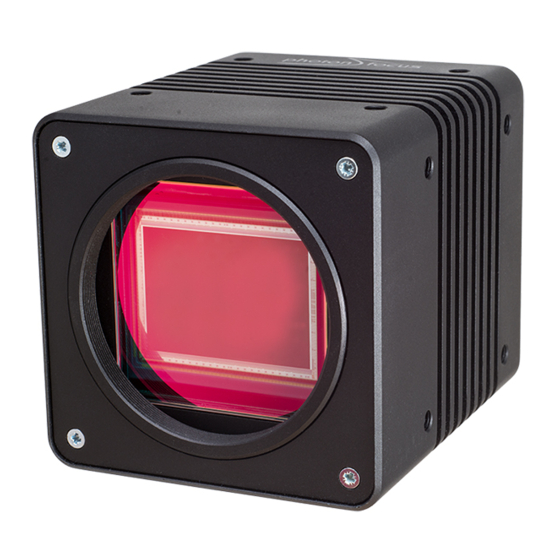
Product Specification 3.1 Introduction The Photonfocus MV8 Gpixel GigE camera series is built around the CMOS image sensor GMAX4651 from Gpixel. It provides a resolution of 8424 x 6032 pixels. The camera series is optimized for low light conditions. The cameras are aimed at standard applications in industrial image processing where high sensitivity and high frame rates are required. - Page 16 3 Product Specification Figure 3.1: Photonfocus MV8 Gpixel 10 GigE camera series MAN094 03/2021 V1.0 16 of 139...
-
Page 17: Feature Overview
3.2 Feature Overview 3.2 Feature Overview The general specification and features of the camera are listed in the following sections. The detailed description of the camera features is given in the following chapters. Characteristics Photonfocus MV8 Gpixel GigE Camera Series Interface Gigabit and 10-Gigabit Ethernet (Copper &... -
Page 18: Technical Specification
3 Product Specification 3.3 Technical Specification 51 MPix Cameras Sensor Manufacturer Gpixel Sensor Type GMAX4651 Technology CMOS active pixel Scanning system progressive scan Optical format / diagonal 35 mm / 47.7 mm Resolution 8424 x 6032 pixels Pixel size 4.6 m x 4.6 m Active optical area 38.75 mm x 27.75 mm Full well capacity... - Page 19 3.3 Technical Specification MV8-D8424(C)-G01 GigE Camera Series Operating temperature / moisture 0°C ... 40°C / 20 ... 80 % (10GigE) Storage temperature / moisture -25°C ... 60°C / 20 ... 95 % Camera Power Supply +12 V DC (- 10 %) ... +24 V DC (+ 10 %) PoE Conformity IEEE 802.3bt standard Class 4 Trigger signal input range...
-
Page 20: Absolute Maximum Ratings
3 Product Specification 3.3.1 Absolute Maximum Ratings Parameter Value Power Supply Voltage -50 V ... +50 V ESD Contact Discharge Power Supply 4 kV ESD Air Discharge Power Supply 8 kV Fast Transients/Bursts Power Supply 2 kV Surge immunity Power Supply 1 kV Camera Control Input Signal Voltage Single Ended -15 V ... - Page 21 3.3 Technical Specification Single Ended Input Voltage Logic Level Fault Condition -15V < VIN < +6V No Fault +6V < VIN < +8V Indeterminate No Fault +8V < VIN < +40V High No Fault Table 3.6: Single-Ended SE-HTL Low Threshold Mode Receiver Logic (LineIn0, LineIn1, LineIn2) Single Ended Input Voltage Logic Level Fault Condition...
-
Page 22: Spectral Response
3 Product Specification 3.3.3 Spectral Response Fig. 3.2 and Fig. 3.3 show the quantum efficiency curve of the monochrome GMAX4651sensor from Gpixel measured in the wavelength range from 350 nm to 900 nm. GMAX4651 Mono 1000 Wavelength [nm] Figure 3.2: Quantum efficiency (QE) [%] of the GMAX4651 monochrome image sensors (with micro lenses and cover glass) GMAX4651 Red Bayer GMAX4651 Green Bayer... -
Page 23: Image Acquisition
Image Acquisition This chapter gives detailed information about the controlling of the image acquisition. It shows how the camera can be triggered or run in free-running mode, and how the frame rate can be configured. The structure offers a lot of flexibility in the configuration. It follows the GenI- Cam naming convention. -
Page 24: Image Acquisition, Frame And Exposure Control Parameters
4 Image Acquisition Acquisition Control The acquisition control block takes care of the acquisition function. The camera can only capture frames, when the acquisition has been started and is active (see Section 4.2 for more information). Frame Control The frame control block takes care of the capturing of one or many frames and burst of frames (see Section 4.3 for more information). -
Page 25: Image Acquisition, Frame And Exposure Trigger
4.1 Overview This list shows only an overview of available parameters. The function and usage of them are explained in the following chapters. 4.1.4 Image Acquisition, Frame and Exposure Trigger The camera can run in "free-running" mode, which means that it captures images automatically in full frame rate once the acquisition has been started. -
Page 26: Acquisition Control
4 Image Acquisition 4.2 Acquisition Control A c q u i s i t i o n T r i g g e r W a i t ) c q u i s i t i o n C o n t r o l A c q u i s i t i o n A c t i v e A c q u i s i t i o n S t a r t T r i g g e r ) c q u i s i t i o n S t a r t ( ) -
Page 27: Acquisition Start Trigger
4.2 Acquisition Control ) c q u i s i t i o n S t a r t ( ) A c q u i s i t i o n S t o p ( ) . r a m e F r a m e . -
Page 28: Acquisition End Trigger
4 Image Acquisition 4.2.4 Acquisition End Trigger The acquisition end trigger can be used to control the acquisition end procedure. The main property of this trigger is the trigger mode. It can be set to on or off: Acquisition End Trigger Mode = on When the acquisition status is "Acquisition Active", it goes to "Acquisition Trigger Wait"... -
Page 29: Frame Control
4.3 Frame Control 4.3 Frame Control . r a m e C o n t r o l F r a m e T r i g g e r W a i t F r a m e A c t i v e F r a m e S t a r t T r i g g e r F r a m e S t a r t F r a m e B u r s t S t a r t T r i g g e r... -
Page 30: Frame Burst End Trigger
4 Image Acquisition A c q u i s i t i o n S t a r t ( ) A c q u i s i t i o n S t o p ( ) . r a m e . -
Page 31: Frame Control Output Signals
4.3 Frame Control A c q u i s i t i o n S t a r t ( ) A c q u i s i t i o n S t o p ( ) . r a m e . -
Page 32: Exposure Control
4 Image Acquisition 4.4 Exposure Control - x p o s u r e C o n t r o l E x p o s u r e A c t i v e E x p o s u r e S t a r t T r i g g e r E x p o s u r e S t a r t E x p o s u r e E n d T r i g g e r E x p o s u r e E n d... -
Page 33: Exposure Control Output Signals
4.4 Exposure Control Exposure End Trigger Mode = on An activated exposure cycle will be terminated and the image read out will be started, as soon as an exposure end trigger has been received. The "Exposure Active" status goes to inactive. Exposure end triggers are only processed, when an exposure start trigger has started a trigger controlled exposure cycle previously. -
Page 34: Overlapped Image Acquisition Timing
4 Image Acquisition 4.5 Overlapped Image Acquisition Timing The camera is able to perform an overlapped image acquisition. It means, a new exposure can be started during the image readout of the previous image. Fig. 4.10 shows an image acquisition procedure when images are captured in overlapped mode. The status "Frame Active"... - Page 35 4.5 Overlapped Image Acquisition Timing which can be counted by a counter (see Section 5.1.5 for more information how to count missed triggers). Fig. 4.11 and Fig. 4.12 shows both timing situations, when the exposure time longer than the read out time and when the exposure time is shorter than the read out time. F r a m e - x p o s u r e R e a d O u t...
-
Page 36: Acquisition-, Frame- And Exposure-Trigger Configuration
4 Image Acquisition 4.6 Acquisition-, Frame- and Exposure-Trigger Configuration The acquisition-, frame- and exposure timing can be controlled by 7 triggers: • Acquisition Start Trigger • Acquisition End Trigger • Frame Start Trigger • Frame Burst Start Trigger • Frame Burst End Trigger •... -
Page 37: Trigger Software
4.6 Acquisition-, Frame- and Exposure-Trigger Configuration Software Signal Pulse A trigger is generated by the software signal pulse, which comes from a common software signal pulse register (see Section 4.7 for more information). Counter Start A trigger signal is generated by the counter start event (see Section 5.1.3 for more information about the counter start event). -
Page 38: Trigger Divider
4 Image Acquisition 4.6.5 Trigger Divider The trigger divider specifies a division factor of the incoming trigger pulses. A division factor of 1 processes every incoming trigger. A division factor of 2 processes every second trigger and so 4.6.6 Trigger Delay The trigger delay lets the user specify a delay, that will be applied between the reception of a trigger event and when the trigger becomes active. -
Page 39: Software Signal Pulse And User Output
4.7 Software Signal Pulse and User Output 4.7 Software Signal Pulse and User Output The software signal pulse block contains eight general purpose registers which allow generating internal pulse signals by software access. These pulse signals are internally connected to following functions, where it can be used to start a procedure: •... - Page 40 4 Image Acquisition MAN094 03/2021 V1.0 40 of 139...
-
Page 41: Counter & Timer
Counter & Timer 5.1 Counter + o u n t e r A c t i v a t i o n C o u n t e r 4 i s i n g E d g e T r i g g e r F a l l i n g E d g e B o t h... -
Page 42: Counter Status
5 Counter & Timer If additionally a trigger source is selected, the counter is waiting for a trigger. It ignores counter events until a valid trigger event has been received. A valid trigger signal on the selected trigger source starts the counter, which means, that it counts the predefined number of events from the start value according to the counter start value and duration configuration. -
Page 43: Counter Event Source
5.1 Counter Counter Trigger Source Off The state of the counter changes to "trigger wait". The counter reset source can be set to the counter end signal of the same counter. This allows to restart the counter automatically as soon as it arrives its end condition. -
Page 44: Counter Trigger Source
5 Counter & Timer MissedFrameBurstStartTrigger Count the number of missed frame burst start triggers. A missed frame burst start trigger event is generated, when a frame burst start trigger cannot be processed. MissedExposureStartTrigger Count the number of missed exposure start triggers. A missed exposure start trigger event is generated, when an exposure start trigger cannot be processed. -
Page 45: Counter Reset Source
5.1 Counter Exposure Start Starts with the reception of the exposure start event. Exposure End Starts with the reception of the exposure end event. User Output 0 ... 7 Starts and counts events as long as the selected user output bit is asserted. When the counter is started, it ignores counter events as long as the corresponding user output bit is deasserted (see Section 4.7). - Page 46 5 Counter & Timer Acquisition End Resets with the reception of the acquisition end event. FrameTrigger Resets with the reception of the frame trigger. Frame Start Resets with the reception of the frame start event. Frame End Resets with the reception of the frame end event. Frame Burst Start Resets with the reception of the frame burst start event.
-
Page 47: Timer
5.2 Timer 6 i m e r T i m e r R e s e t ( ) T i m e r S t a t u s T i m e r A c t i v e A c t i v a t i o n T i m e r 6 i m e r V a l u e... -
Page 48: Timer Active, -Start And -End Signal
5 Counter & Timer 5.2.3 Timer Active, -Start and -End Signal Timer Active An asserted timer active signal indicates, that the timer has started counting the configured duration period. The timer active signal is internally routed to the I/O control block and can there be selected for output on the physical output line or on one of the available leds. - Page 49 5.2 Timer Action 0 ... 3 Starts with the reception of the chosen action signal event. Software Signal Pulse 0 ... 7 Starts with the reception of chosen software signal pulse event (see Section 4.7). Line Input Starts when the specified counter trigger activation condition is met on the chosen line.
- Page 50 5 Counter & Timer MAN094 03/2021 V1.0 50 of 139...
-
Page 51: Encoder
Encoder - n c o d e r E n c o d e r S o u r c e A E n c o d e r R e s e t ( ) E n c o d e r S t a t u s E n c o d e r T r i g g e r E n c o d e r E n c o d e r V a l u e... -
Page 52: Encoder Trigger Output
6 Encoder G r a y C o u n t e r H i g h R e s o l u t i o n C o u n t e r F o u r P h a s e C o u n t e r Figure 6.2: Encoder Modes 6.2 Encoder trigger output The trigger output of the encoder reacts to changes of the position counter. -
Page 53: Encoder Reset Source
6.4 Encoder Reset Source Encoder Idle Encoder is idle, either no trigger sources are configured or the encoder is waiting on the reset. Encoder Up The position counter last incremented. Encoder Down The position counter last decremented. Encoder Static The position counter hasn’t changed in the EncoderTimeout period. The encoder also switches to this state when it is reset while in the idle state. - Page 54 6 Encoder Rising Edge Encoder starts with the rising edge on the selected line input. Falling Edge Encoder starts with the falling edge on the selected line input Both Edges Encoder starts with any edge on the selected line input Level High Resets the encoder as long as the level is high.
-
Page 55: O Control
I/O Control This chapter shows the structure of the physical input and physical output lines. It describes the signal path and how to configure it. The I/O control block contains a signal input path and a signal output path. 7.1 Input Signal Path The camera has four physical signal input lines, which come from the input opto-isolator of the camera hardware interface (see Section 13.6) and which are fed into the input signal path of the camera. -
Page 56: Output Signal Path
7 I/O Control 7.2 Output Signal Path The camera has three physical signal output line and two LEDs. The physical output lines are connected to the output opto-isolator in the camera hardware interface (see Section 13.6). The output lines, LED0 and LED1 have their own output signal path which is shown in Fig. 7.2. The source can be selected and the selected signal can be invert before it is sent out of the camera. -
Page 57: Action Control
Action Control ) c t i o n C o n t r o l A c t i o n U n c o n d i t i o n a l M o d e ) c t i o n D e v i c e K e y A c t i o n 3 A c t i o n 2 A c t i o n 3... -
Page 58: Action Control Output
8 Action Control 8.2 Action Control Output The action output signals can be used to trigger other blocks, like counter, timer, acquisition, frame or exposure control. MAN094 03/2021 V1.0 58 of 139... -
Page 59: Image Format Control
Image Format Control The focus on the interesting parts of an image can be set by setting the region of interest (ROI) (see Section 9.1). The ROI influences the image size which leads into an increased frame rate (see Chapter 10 for more information about the available frame rate). - Page 60 9 Image Format Control On the left-hand side an example of ROI is shown and on the right-hand side an example of MROI. It can be readily seen that the resulting image with MROI is smaller than the resulting image with ROI only and the former will result in an increase in image frame rate. R O I .
- Page 61 9.2 Multiple Regions of Interest Figure 9.2: Multiple Regions of Interest with 5 ROIs MAN094 03/2021 V1.0 61 of 139...
- Page 62 9 Image Format Control Fig. 9.3 shows an example from hyperspectral imaging where the presence of spectral lines at known regions need to be inspected. By using MROI only a 640x54 region need to be readout, and a much higher frame rate is possible, which can’t be achieved without using MROI. $ 5 6 p i x e l ( 0 , 0 ) 1 p i x e l...
-
Page 63: Pixel Format
Table 9.1: Available pixel formats for different cameras and available binning settings Binning BayerGR8 BayerGR10 BayerGR12 BayerGR10 Packed BayerGR12 Packed MV8-D8424-G01-GT Enabled Disabled MV8-D8424C-G01-GT Enabled Disabled Table 9.2: Available pixel formats for different cameras and available binning settings MAN094 03/2021 V1.0... -
Page 64: Decimation (Monochrome Cameras)
9 Image Format Control 9.4 Decimation (monochrome cameras) Decimation reduces the number of pixels in y-direction. Decimation in y-direction transfers every n row only and directly results in reduced read-out time and higher frame rate respectively. Decimation can also be used together with ROI or MROI. In this case every ROI should have a height that is a multiple of the decimation setting. - Page 65 9.4 Decimation (monochrome cameras) 0 , 0 ) R O I m a x m a x Figure 9.5: Decimation and ROI ( 0 , 0 ) R O I M R O I 0 M R O I 1 M R O I 2 m a x m a x...
- Page 66 9 Image Format Control The image in Fig. 9.7 on the right-hand side shows the result of decimation 3 of the image on the left-hand side. Figure 9.7: Image example of decimation 3 An example of a high-speed measurement of the elongation of an injection needle is given in Fig.
-
Page 67: Frame Rate
Frame Rate The frame rate depends on the image size, the used exposure time and the max data rate of the GigE interface (MaxDataRateInterface). Table 10.1 a shows the maximum frame rates for some common image dimensions. 10.1 Maximum Frame Rate A list of commonly used image dimensions and its frame rates is shown on Table 10.1 for standard cameras. - Page 68 10 Frame Rate MAN094 03/2021 V1.0 68 of 139...
-
Page 69: Pixel Data Processing
Pixel Data Processing 11.1 Overview The pixel, which are read out of the image sensor, are processed in the cameras data path. The sequence of blocks is shown in figure Fig. 11.1. Figure 11.1: Camera data path MAN094 03/2021 V1.0 69 of 139... -
Page 70: Column Group Correction
11 Pixel Data Processing 11.2 Column Group Correction Due to the readout structure of the image sensors there are non uniformities in an image. The Column Group Correction corrects dark signal non uniformities (DSNU) as well as Pixel response non uniformities (PRNU) column wise. The correction parameters are obtained by a calibration process. -
Page 71: Storing The Calibration In Permanent Memory
11.4 Gain and Offset Every pixel that is above the higher threshold or below the lower threshold is marked as a bad (defect) pixel. The values of these thresholds can be set by the properties BadPixelCorrection_LowThreshold and BadPixelCorrection_HighThreshold. These values must match with acquired image used for calibration: only defect pixels should have a value below BadPixelCorrection_LowThreshold or above BadPixelCorrection_HighThreshold. -
Page 72: Grey Level Transformation (Lut)
11 Pixel Data Processing Digital Fine Gain and Digital Gain may result in missing codes in the output im- age data. A user-defined value can be subtracted from the gray value in the digital offset block. If digital gain is applied and if the brightness of the image is too big then the interesting part of the output image might be saturated. - Page 73 11.5 Grey Level Transformation (LUT) y = f ( x ) m a x m a x Figure 11.2: Commonly used LUT transfer curves Grey level transformation − Gain: y = (255/1023) ⋅ a ⋅ x a = 1.0 a = 2.0 a = 3.0 a = 4.0 1000...
-
Page 74: Gamma
11 Pixel Data Processing 11.5.2 Gamma The ’Gamma’ mode performs an exponential amplification, configurable in the range from 0.4 to 4.0. Gamma > 1.0 results in an attenuation of the image (see Fig. 11.4), gamma < 1.0 results in an amplification (see Fig. 11.5). Gamma correction is often used for tone mapping and better display of results on monitor screens. -
Page 75: User-Defined Look-Up Table
11.5 Grey Level Transformation (LUT) 11.5.3 User-defined Look-up Table In the ’User’ mode, the mapping of input to output grey levels can be configured arbitrarily by the user. This procedure is explained in Section C.4. 7 s e r L U T y = f ( x ) 8 b i t 1 2 b i t... - Page 76 11 Pixel Data Processing ( 0 , 0 ) N N N N O O L U T 0 O L U T 1 O m a x m a x Figure 11.7: Overlapping Region-LUT example...
- Page 77 11.5 Grey Level Transformation (LUT) Fig. 11.9 shows the application of the Region-LUT to a camera image. The original image without image processing is shown on the left-hand side. The result of the application of the Region-LUT is shown on the right-hand side. One Region-LUT was applied on a small region on the lower part of the image where the brightness has been increased.
-
Page 78: Binning
11 Pixel Data Processing 11.6 Binning 11.6.1 Description Binning sums the pixels in subsequent columns and rows, according to the binning configuration. The result is then divided by the number of binned pixels. The binning feature will result in images with lower resolution but significantly higher SNR. For instance, 2x2 binning will result in roughly twice the SNR (in bright areas of the image). - Page 79 11.6 Binning MAN094 03/2021 V1.0 79 of 139...
-
Page 80: Dual Crosshairs
11 Pixel Data Processing 11.7 Dual Crosshairs Up to two crosshairs can be displayed in the live image. It inserts one or two vertical and horizontal lines into the image. The positions as well as the gray levels of the line for both crosshairs can be set individually via the camera software. - Page 81 11.7 Dual Crosshairs The x- and y-positons are absolute to the sensor pixel matrix. It is independent on the image format settings (see Chapter 9 for more information about the available image format configurations). Fig. 11.12 shows two situations of the crosshairs configuration. The same image format settings are used in both situations.
-
Page 82: Test Images
11 Pixel Data Processing 11.8 Test Images Test images are generated in the camera FPGA, independent of the image sensor. They can be used to check the transmission path from the camera to the acquisition software. Independent from the configured grey level resolution, every possible grey level appears the same number of times in a test image. - Page 83 11.8 Test Images Figure 11.14: LFSR (linear feedback shift register) test image In the LFSR (linear feedback shift register) mode the camera generates a constant pseudo-random test pattern containing all grey levels. If the data transmission is correctly received, the histogram of the image will be flat (Fig. 11.15). On the other hand, a non-flat histogram (Fig.
-
Page 84: Status Line And Image Information
11 Pixel Data Processing Figure 11.16: LFSR test pattern received and histogram containing transmission errors 11.9 Status Line and Image Information There are camera properties available that give information about the acquired images, such as integration time, ROI settings or average image value. These properties can be queried by software. - Page 85 11.9 Status Line and Image Information Start pixel index Parameter width [bit] Parameter Description Preamble: 0x66BB00FF Counter 0 Value (see Section 5.1) Counter 1 Value (see Section 5.1) Counter 2 Value (see Section 5.1) Counter 3 Value (see Section 5.1) Timer 0 Value in units of clock cycles (see Section 5.2) Timer 1 Value in units of clock cycles (see Section...
-
Page 86: Camera Type Codes
11 Pixel Data Processing 11.9.3 Camera Type Codes Camera Model Camera Type Code MV8-D8424-G01-GT MV8-D8424C-G01-GT Table 11.4: Type codes of Photonfocus MV8 Gpixel GigE camera series MAN094 03/2021 V1.0 86 of 139... -
Page 87: Frame Combine
11.10 Frame Combine 11.10 Frame Combine Very high frame rates that are well over 1000 fps can be achieved for small ROIs. Every frame (image) activates an interrupt in the GigE software which will issue a high CPU load or the frame rate can not be handled at all by an overload of interrupts. - Page 88 11 Pixel Data Processing FrameCombine_ForceTimeout The transmission of the combined frame is forced by writing to the FrameCombine_ForceTimeout property. When the FrameCombine is finished by a timeout, then the remaining data in the combined frame will be filled with filler data: the first two pixels of every filler row have the values 0xBB (decimal 187) and 0x44 (decimal 68).
-
Page 89: Precautions
Precautions 12.1 IMPORTANT NOTICE! READ THE INSTRUCTIONS FOR USE BEFORE OPERATING THE CAMERA STORE THE INSTRUCTIONS FOR USE FOR FURTHER READING The installation of the camera in the vision system should be executed by trained and instructed employees. DANGER - Electric Shock Hazard Unapproved power supplies may cause electric shock. - Page 90 12 Precautions Incorrect plugs can damage the camera connectors. Use only the connectors specified by Photonfocus in this manual. Using plugs designed for a smaller or a larger number of pins can damage the connectors. The cameras deliver the data to the vision system over interfaces with high band- width.
- Page 91 12.1 IMPORTANT NOTICE! Cleaning of the housing To clean the surface of the camera housing: • Before cleaning disconnect the camera from camera power supply and I/O connectors. • Do not use aggressive solvents or thinners which can damage the surface, the serial number label and electronic parts.
- Page 92 12 Precautions MAN094 03/2021 V1.0 92 of 139...
-
Page 93: Hardware Interface
Hardware Interface 13.1 Absolute Maximum Ratings Parameter Value Power Supply Voltage -50 V ... +50 V ESD Contact Discharge Power Supply 4 kV ESD Air Discharge Power Supply 8 kV Fast Transients/Bursts Power Supply 2 kV Surge immunity Power Supply 1 kV Camera Control Input Signal Voltage Single Ended -15 V ... - Page 94 13 Hardware Interface Single Ended Input Voltage Logic Level Fault Condition -15V < VIN < +6V No Fault +6V < VIN < +8V Indeterminate No Fault +8V < VIN < +40V High No Fault Table 13.3: Single-Ended SE-HTL Low Threshold Mode Receiver Logic (LineIn0, LineIn1, LineIn2) Single Ended Input Voltage Logic Level Fault Condition...
-
Page 95: Gige Camera Connector
13.3 GigE Camera Connector 13.3 GigE Camera Connector The MV8 10 GigE copper cameras are interfaced to external components via • an X-coded M12 GigE connector to transmit configuration, image data and trigger. • a 17-pin M12 I/O connector with 4 digital inputs 3 digital outputs and one RS485 interface. •... -
Page 96: Power Supply / Power Over Ethernet (Poe)
13 Hardware Interface 13.4 Power Supply / Power Over Ethernet (PoE) When the camera is powered via wall adapter it requires a single voltage input (see Table 3.3). The camera meets all performance specifications using standard switching power supplies, although well-regulated linear power supplies provide optimum performance. It is extremely important that you apply the appropriate voltages to your camera. -
Page 97: Status Indicator (Gige Cameras)
13.5 Status Indicator (GigE cameras) 13.5 Status Indicator (GigE cameras) Four LEDs (S1, S2, S3 and S4) on the back of the camera give information about the current status of the GigE CMOS cameras. Function GigE (G2) 10 GigE Copper (GT) 10 GigE Fibre (FB) IO Fault S1 red... -
Page 98: I/O Connector
13 Hardware Interface 13.6 I/O Connector 13.6.1 Overview The 17-pin M12 I/O connector contains four external line inputs, three external line outputs and one optional RS485 communication interface. All inputs and outputs are isolated. The pinout of the I/O connector is described in Appendix A. A suitable trigger breakout cable, as well as a breakout box, for 17-pin M12 I/O connector can be ordered from your Photonfocus dealership. - Page 99 13.6 I/O Connector I/O Standard Signalling R0, R1 & R2 C0, C1, & C2 Threshold TTLTerminated120 Single Ended 10 nF n.a. TTLTerminated270 Single Ended 100 pF n.a. RS422 Differential 10 nF n.a. D-HTL Differential 100 pF n.a. SE-HTL Low Threshold Single Ended 100 pF SE-HTL High Threshold...
-
Page 100: Input Fault Detection
13 Hardware Interface 13.6.2 Input Fault Detection All inputs support a fault detection which signalises irregular conditions such as small differential signals, shorts, opens, overvoltages and undervoltages. The fault condition of each input can be read out by a software parameter. A fault condition remains active until it is acknowledged by a software command. - Page 101 13.6 I/O Connector Camera 17-pin M12 CAMERA_PWR I/O Connector CAMERA_GND YOUR_POWER TTL or SE-HTL Isolator ISO_IN0 & LineIn0 YOUR_GND ISO_IN1 YOUR_POWER LineIn1 4.7k ISO_IN2 LineIn2 YOUR_GND TTL120 ISO_IN3 10nF LineIn3 ¡ YOUR_GND ISO_GND Figure 13.3: Example of input connections MAN094 03/2021 V1.0 101 of 139...
-
Page 102: Encoder Interface
13 Hardware Interface 13.6.4 Encoder Interface Fig. 13.4 and Fig. 13.5 show, how differential and single ended encoder must be connected to the GigE camera’s I/O interface. Encoder A and B singals must be connected to LineIn0 and LineIn1. They can be connected in either way, as long as the encoder is configured accordingly Section C.5. - Page 103 13.6 I/O Connector Camera 17-pin M12 CAMERA_PWR I/O Connector CAMERA_GND Encoder TTL or SE-HTL Isolator ISO_IN0 LineIn0 ISO_IN1 LineIn1 ISO_IN2 LineIn2 TTL120 ISO_IN3 ALARM 10nF LineIn3 ¡ ISO_GND YOUR_GND Figure 13.5: Connection of a single ended encoder MAN094 03/2021 V1.0 103 of 139...
-
Page 104: Single-Ended Line Output
13 Hardware Interface 13.6.5 Single-ended Line Output ISO_OUT0, ISO_OUT1 and ISO_OUT2 are single-ended isolated output. Fig. 13.6 shows the connection from the ISO_OUT output to a TTL logic device. 17-pin M12 Camera I/O Connector CAMERA_PWR YOUR_POWER CAMERA_GND YOUR_POWER Isolator ISO_OUT0 LineOut0 ISO_OUT1 LineOut1... -
Page 105: Master / Slave Camera Connection
13.6 I/O Connector 13.6.6 Master / Slave Camera Connection The line output of one Photonfocus GigE camera can easily be connected to a line input of another Photonfocus GigE camera as shown in Fig. 13.8. This results in a master/slave mode where the slave camera operates synchronously to the master camera. -
Page 106: I/O Wiring
13 Hardware Interface 13.7 I/O Wiring The Photonfocus cameras include electrically isolated inputs and outputs. Take great care when wiring trigger and strobe signals to the camera, specially over big distances (a few meters) and in noisy environments. Improper wiring can introduce ground loops which lead to malfunction of triggers and strobes. -
Page 107: Common Grounds With Star Wiring
13.7 I/O Wiring 13.7.2 Common Grounds with Star Wiring Ground loops can be avoided using "star wiring", i.e. the wiring of power and ground connections originate from one "star point" which is typically a power supply. Fig. 13.10 shows a schematic of the star-wiring concept. Fig. - Page 108 13 Hardware Interface Fig. 13.12 shows an example of how to connect a flash light and a trigger source to the camera using star-wiring. The trigger in this example is generated from a light barrier. Note how the power and ground cables are connected to the same power supply. Power Supply Flash Light Barrier...
- Page 109 13.7 I/O Wiring An example of improper wiring that causes a ground loop is shown in Fig. 13.13. Connecting CAMERA_GND and ISO_GND the wrong way, ground loop! Isolator ISO_IN ISO_GND CAMERA_GND Ground Loop Ground plane voltage difference Figure 13.13: Improper I/O wiring causing a ground loop MAN094 03/2021 V1.0 109 of 139...
- Page 110 13 Hardware Interface MAN094 03/2021 V1.0 110 of 139...
-
Page 111: Mechanical Considerations
Mechanical Considerations 14.1 Mechanical Interface During storage and transport, the camera should be protected against vibration, shock, moisture and dust. The original packaging protects the camera adequately from vibration and shock during storage and transport. Please either retain this packaging for possible later use or dispose of it according to local regulations. - Page 112 14 Mechanical Considerations For long life and high accuracy operation, we highly recommend to mount the camera thermally coupled, so that the mounting acts as a heat sink. To verify proper mounting, camera temperature can be monitored using the GeniCam command DeviceTemperature under GEVDeviceControl.
-
Page 113: Optical Interface
14.2 Optical Interface 14.2 Optical Interface 14.2.1 Cleaning the Sensor The sensor is part of the optical path and should be handled like other optical components: with extreme care. Dust can obscure pixels, producing dark patches in the images captured. Dust is most visible when the illumination is collimated. - Page 114 14 Mechanical Considerations Product Supplier Remark EAD400D Airduster Electrolube, UK www.electrolube.com Anticon Gold 9"x 9" Wiper Milliken, USA ESD safe and suitable for class 100 environments. www.milliken.com TX4025 Wiper Texwipe www.texwipe.com Transplex Swab Texwipe Small Q-Tips SWABS Q-tips Hans J. Michael GmbH, www.hjm-reinraum.de BB-003 Germany...
-
Page 115: Troubleshooting
Troubleshooting 15.1 No images can be acquired If no images can be acquired then the cause could be one of the following: Camera is not triggered: see Section 15.1.1 First proceed with the above list in numerical order. If still no images can be acquired go back to step 2. - Page 116 15 Troubleshooting MAN094 03/2021 V1.0 116 of 139...
-
Page 117: Standards Compliance
Standards Compliance 16.1 Directives and General Standards The products described in this manual in the form as delivered are in conformity with the provisions of the following European Directives: • 2014/30/EU Electromagnetic compatibility (EMC) • 2014/35/EU Low Voltage (LVD) • 2011/65/EU Restriction of hazardous substances (RoHS) Conformity to the Directives is assured through the application of the following standards: Emission:... -
Page 118: For Customers In Canada
16 Standards Compliance You are cautioned that any changes or modifications not expressly approved in this manual could void your authority to operate this equipment. The shielded interface cable recommended in this manual must be used with this equipment in order to comply with the limits for a computing device pursuant to Subpart B of Part 15 of FCC Rules. -
Page 119: Warranty
Warranty The manufacturer alone reserves the right to recognize warranty claims. 17.1 Warranty Terms The manufacturer warrants to distributor and end customer that for a period of two years from the date of the shipment from manufacturer or distributor to end customer (the "Warranty Period") that: •... - Page 120 17 Warranty Avoid cleaning the sensor with improper methods. Follow the instructions in the corresponding chapter of this manual. Transport and store the camera in its original packaging only and protect the sensor and the lens mount with a camera body cap. 10.
-
Page 121: Support And Repair
Support and Repair This chapter describes the product support and repair. 18.1 Technical Support First level technical support is given from the sales department of Photonfocus or your local dealer. In case your issue could not be solved in this way Photonfocus support team takes over. The Photonfocus support team is available via email: support@photonfocus.com. - Page 122 18 Support and Repair MAN094 03/2021 V1.0 122 of 139...
-
Page 123: References
References All referenced documents can be downloaded from our website at www.photonfocus.com. MAN094 03/2021 V1.0 123 of 139... - Page 124 19 References MAN094 03/2021 V1.0 124 of 139...
-
Page 125: A Pinouts
Pinouts A.1 I/O Connector The I/O plug is available from PHOENIX CONTACT connectors www.phoenixcontact.com. Fig. A.1 shows the I/O plug from the solder side. The pin assignment of the I/O plug is given in Table A.2. It is extremely important that you apply the appropriate voltages to your camera. Incorrect voltages will damage or destroy the camera. - Page 126 A Pinouts I/O Type Name Description CAMERA_GND Camera GND, 0V CAMERA_PWR Camera Power ISO_INC0_P / ISO_IN0 Differential configuration: Isolated RS422/HTL differential input, positive polarity. Single ended configuration: Isolated TTL/HTL single ended input. ISO_INC0_N / ISO_GND Differential configuration: Isolated RS422/HTL differential input, negative polarity. Single ended configuration: Must be tied to ISO_GND.
-
Page 127: Gige Connector
A.2 GigE Connector A.2 GigE Connector An X-coded M12 connector is used for the GigE interface and power supply of the camera. Suitable GigE interface cables can be ordered from your Photonfocus dealership. MAN094 03/2021 V1.0 127 of 139... - Page 128 A Pinouts MAN094 03/2021 V1.0 128 of 139...
-
Page 129: B Camera Timing
Camera Timing B.1 Timed Exposure Mode Camera Timing Fig. B.1 shows a timing example, when the camera capture frames with rising edges on the camera ISO_IN input. The external signal, which is fed into the cameras ISO_IN input is isolated by an opto-isolator. - Page 130 B Camera Timing 1 S O _ I N L i n e I n i s o - i n I n t e r n a l L i n e I n P u l s e i n p u t - j i t t e r D e l a y e d L i n e I n P u l s e p u l s e - d e l a y...
-
Page 131: C Use Cases
Use Cases This chapter shows some typical configurations of the camera. It gives some tips, how to acquire images and how to use the general purpose counters and timers. C.1 Acquisition This section shows some configuration procedures of frequently used acquisition situations. C.1.1 Camera runs in "free-running"... -
Page 132: Camera Runs In Burst Triggered Mode
C Use Cases The TriggerMode of FrameStart trigger must be set to On. The AcquisitionStart, FrameBurstStart and the ExposureStart must be set to Off. The TriggerSource of the FrameStart trigger must be set to the corresponding source. For instances to Line0. Since the source is set to Line0, the TriggerActivation must be set accordingly: RisingEdge, FallingEdge or AnyEdge. -
Page 133: Trigger Controlled Exposure Mode
C.2 Timer The required PixelFormat must be set. 10. AcquisitionMode must be set to Continuous. 11. The software command AcquisitionStart() must be applied. It might be necessary to adjust the polarity of the Line0 input signal. This can be done by the parameter LineInvert in the section DigitalIOControl. -
Page 134: Counter
C Use Cases Set the LineSelector to LineOut0. Set the LineSource of this output to the corresponding timer acitve signal: Timer0Active, Timer1Active, Timer2Active or Timer3Active. Set the polarity of this output accordingly with the parameter LineInverter. C.3 Counter There are four general purpose counters available, which can be used to count any events in the camera. -
Page 135: Missed Trigger Counter
C.4 Look-Up Table (LUT) Configure the time stamp tick value CounterTimeStampTickValue. For instances a value of 1 s generates an event every 1 s. All other counter parameter must be left in default state (Both the CounterResetSource and CounterTriggerSource must be set to Off) The counter needs to be reset (see C.3.1). -
Page 136: Region Lut
C Use Cases C.4.3 Region LUT The Region LUT feature is described in Section 11.5.4. Procedure to set the Region LUT: Set LUT_EnRegionLUT (in category RegionLUT) to False. This is not mandatory but recommended. Set LUTEnable (in category LUTControl) to False. This is not mandatory but recommended. Select LUT 0 by setting LUTSelector (in category LUTControl) to 0. -
Page 137: Configuration Of The Encoder Ab Signals
C.5 Encoder C.5.1 Configuration of the encoder AB signals The A and B signal of the encoder need to be connected to LineIn0 and LineIn1. It can be connected in either way. Configure the LineFormat of LineIn0 and LineIn1 according to the encoder output standard. Configure EncoderSourceA and EncoderSourceB of the EncoderControl respectively. - Page 138 C Use Cases MAN094 03/2021 V1.0 138 of 139...
-
Page 139: D Document Revision History
Document Revision History Revision Date Changes March 2021 First Version MAN094 03/2021 V1.0 139 of 139...
Need help?
Do you have a question about the MV8-D8424-G01-GT and is the answer not in the manual?
Questions and answers