Advertisement
Advertisement
Table of Contents

Related Manuals for Mastech MS2001


Summary of Contents for Mastech MS2001
- Page 1 OPERATOR’S INSTRUCTION MANUAL DIGITAL CLAMP METER...
- Page 2 CONTENTS PAGE SAFETY INFORMATION ….……………………..…………... SAFETY SYMBOLS ..………………………………….….….. SAFETY PRECAUTIONS ………………………………..… MAINTENANCE .………..……………………………..……. GENERAL DESCRIPTION …..…..………………………..FRONT PANEL DESCRIPTION …..………..………..……. OPERATING INSTRUCTIONS .………..……………..……. SPECIFICATIONS ..…...……………………..………...…….. REPLACING THE BATTERY ..…………….…….……..…. ACCESSORIES ...………..…………………………………….
-
Page 3: Safety Information
SAFETY INFORMATION The digital clamp meter has been designed according to IEC1010– 1 and IEC1010–2–032 concerning safety requirements for electrical measuring instruments and hand – held current clamps with overvoltage category 1000V CAT II 600V CAT III and pollution SAFETY SYMBOLS Important safety information, refer to the operating manual. -
Page 4: Safety Precautions
SAFETY PRECAUTIONS Follow all safety and operating instructions to ensure maximum personal safety during the operation and to ensure the meter is used safely and is kept in good operating condition. • Read these operating instructions thoroughly completely before operating your meter. Pay particular attention to WARNINGS, which will inform you of potentially dangerous procedures. -
Page 5: Maintenance
MAINTENANCE • Before opening the case, always disconnect test leads from all energized circuits. • Never use the meter unless the back cover is in place and fastened completely. • Do not use abrasives or solvents on the meter. To clean it using a damp cloth and mild detergent only. - Page 6 Back light To use this function, press the LIGHT button. When this button is pushed, the Back light of display is on. After about 3 − 5 seconds, the Back light is self-off. The Back light is on again, just push this button once. Display 3 1/2 digit, 7 segment, 16mm high, LCD.
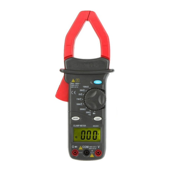
- Page 7 CLAMP METER LAYOUT...
-
Page 8: Operating Instructions
OPERATING INSTRUCTIONS DC VOLTAGE MEASUREMENT Connect the red test lead to the “V” jack and the black lead to the “COM” jack. Set rotary switch at desired 1000V position. Connect test leads across the source or load being measured. Read voltage value on the LCD display along with the polarity of the red lead connection. - Page 9 RESISTANCE MEASUREMENT Connect the red test lead to “Ω ” jack and black test lead to the “COM” jack (The polarity of red lead is positive “+”). Set the rotary switch at desired ”Ω” range position. Connect test leads across the resistor to be measured and read LCD display.
-
Page 10: Specifications
Set the rotary switch at “ ” position. Connect the red test lead to the anode of the diode to be tested and the black test lead to the cathode of the diode. The approx. forward voltage drop of the diode will be displayed. - Page 11 DC VOLTAGE Range Resolution Accuracy ±1.0% of rdg ± 2 digits 1000V Input Impedance: 10MΩ AC VOLTAGE Range Resolution Accuracy ±1.0 % of rdg ± 5 digits 750V Input Impedance: 10MΩ Frequency range: 40Hz to 400Hz. Response: Average responding, calibrated in rms. of a sine wave. AC CURRENT Range Resolution...
-
Page 12: Replacing The Battery
REPLACING THE BATTERY WARNING Before attempting to open the case of battery, always be sure that test leads have been disconnected from measurement circuits. Close case and tighten screws completely before using the meter to avoid electrical shock hazard. If “ ”appears on display, it indicates that the battery should be replaced. - Page 13 CAUTION: Using this appliance in an environment with a strong radiated radio-frequency electromagnetic field (approximately 3V/m), may influence its measuring accuracy. The measuring result can be strongly deviating from the actual value. -11-...
- Page 14 HYS004845...
Need help?
Do you have a question about the MS2001 and is the answer not in the manual?
Questions and answers