Advertisement
Quick Links
Advertisement

Related Manuals for Mastech MS2025C


Summary of Contents for Mastech MS2025C
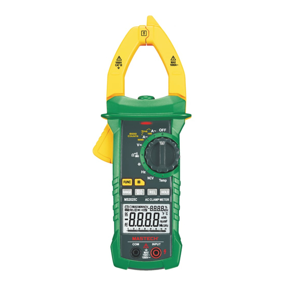
- Page 1 MS2025C CAT III 1000V...
- Page 2 CONTENTS CONTENTS 1. Safety Information ........01 4.6 Automatic Power-Off ........15 1.1 Preliminary ............01 4.7 Measurement Preparation ......16 4.8 Current Measurement ........16 1.2 Usage .............02 4.9 AC Voltage Measurement ......17 1.3 Symbols ............03 4.10 DC Voltage Measurement ......18 1.4 Maintenance ...........03 4.11 Frequency and Duty Cycle ......19 2.
- Page 3 WARNING Be extremely careful when using this meter. Improper use of this device can result in electric shock or destruction of the meter. Take all normal safety precautions and follow the safeguards suggested in this manual. To exploit full functionality of the meter and ensure safe operation, please read carefully and follow the directions in this manual.
- Page 4 1.3 Symbols 1.4.4 Clean the meter with damp cloth and mild detergent. Do not use abrasives or solvents. Note-Important safety information, refer to the 1.4.5 Power off the meter when the meter is not used. instruction manual. Switch the measuring range to OFF position. Application around and removal from UNINSULATED 1.4.6 If the meter is not used for long time, remove the HAZARDOUS LIVE conductors is permitted.
- Page 5 (16) Protective Barrier (to warn the operator of the limit of safe access)
- Page 6 3.1.12 Power supply: DC 9V battery (battery type: NEDA 1604, 006P or 6F22) 238x92x50mm...
- Page 9 3.2.10 Duty cycle 0.1~99.9% 0.1% ±(3.0%)
- Page 12 4.11 Frequency And Duty Ratio Measurement 2) In Voltage Measurement Mode: 1) Clamp head measuring frequency Warning (through AC current): Electric shock hazard. Pay special attention to avoid shock when Warning measuring high voltage. Electric shock hazard. Don't input voltage more than AC 750 RMS. Remove the probe from the meter before measuring with current clamp.
- Page 13 (1) Insert black probe to COM jack, insert red probe to NPUT ack. (2) Transfer switch is placed to position HZ. (3) Connect the probe with signal or both ends of load in parallel for measurement. (4) Read on the LCD. (5) Pressing “Hz/%”...
- Page 14 WARNING To avoid electric shock, make sure that the test leads have been clearly move away from the circuit under measurement before opening the battery cover. 5.1.1. If the symbol “ ” appears, it means that the batteries should be replaced. 5.1.2.
- Page 15 5.2 Replace Probe Replace test leads if leads become damaged or worn. WARNING Use meet EN 61010-031 standard, rated CAT III 1000V, or better test leads. WARNING To avoid electric shock, make sure the probes are disconnected from the measured circuit before removing the rear cover.
Need help?
Do you have a question about the MS2025C and is the answer not in the manual?
Questions and answers