
Related Manuals for Mastech MS2010B


Summary of Contents for Mastech MS2010B
-
Page 1: Table Of Contents
Contents Safety information . 1-1.Safety precaution 1-2. Symbols 2. Meter illustration 2-1. Panel description 2-2. LCD display 3. Specification AC Leakage Current Clamp Meter 3-1. General feature 3-2 Electric specification Instruction Manual 4. Operating instruction 4-1 LPF using 4-2 Data HOLD 4-3 Range Switching 4-4 Function selection 4-5 Maxim value... -
Page 2: Safety Information
5-7. Continuity check or dew full. - 3 - ● You always are careful when working with voltage above 5-8 .Capacitance measurement 60V DC or 30V AC rms. 5-8. Temperature measurement ● Keep fingers behind the clamp barrier while measuring 6. -
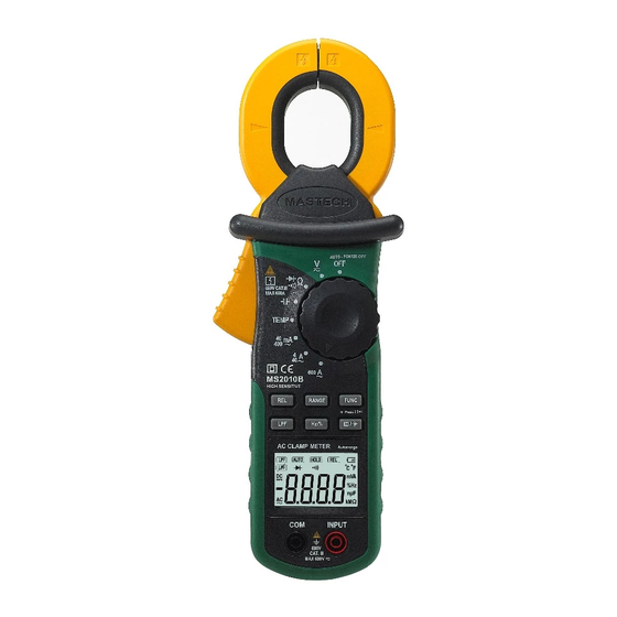
Page 3: Panel Description
‘INPUT’ terminal . 12. ‘COM’ terminal 13. ‘REL’ push button: Relative measurement mode 3999 Fig.1 MS2010B Front arrangement - 5 - 2-1 Panel description - 6 - 2-2. LCD display Clamp jaw ; it is as current transformer(CT) when measuring current flowing through the conductor . -
Page 4: Specification
k Hz , Frequency unites 3. Specification G eneral feature . ● Auto ranging Digital Clamp Meter. But the meter may select manual Function mode by ‘RANGE’button. ● 3 1/2 digit(200 count) LCD display ● Over load indication ‘OL’symbol will displayed on the LCD. ;... - Page 5 400mA 0.1mA 60~10KHz) 10mV ± 0 .7%rdg+3dgt 10MΩ ( ) ± 1 %rdg+8dgt ( ) 400V 0.1V No available 10mA 600V ± 0 .8%rdg+5dgt ( ) [4] Frequency & Duty cycle measurement 400A 100mA The meter is may be measuring the frequency and duty cycle in the AC current 600A ±...
- Page 6 400nF 0.1nF 1000Hz 0.1Hz ± 1 .5%rdg+5dgt circuit) 250V DC or AC rms ( ) ± 4 %rdg+5dgt (by PTC protection 10KHz ( ) circuit) 40uF 0.01uF 100KHz 10Hz ± 2 %rdg+5dgt ( ) 100 uF 0.1 uF >100KHz No available 1 to 99% 0.1% ±3%...
-
Page 7: Range Switching
accurate readings on low frequency response. 15secs, back light will disable. 4-2. Data HOLD 4-7. Sleep mode (Auto power OFF) The push key is used to maintain the measurement data unchanging. If the meter is idle for more than 15minutes, the meter automatically turns Press ‘HOLD”... -
Page 8: Leakage Current Measurement
one line only between the two transmission ine . Set rotary switch to the 40/400mA, 4/.40A or 400A position. 5-2. Leakage current measurement Press the clamp trigger to open jaw and clamp a conductor in that This meter can measure the leakage current on the one-phase or three-phase flowed circuit equipment as well as the conductor in that flow the leakage current. -
Page 9: Diode Check
● If diode is shorted, the display shows ‘0’(zero)in both direction. subtract the readied contact resistance value from the reading value. ● If display shows ‘OL’ in direction, the diode is open. ● For high resistance measurement(>10MΩ), it is normal taking several 5-7. - Page 10 - 18 - 6-3. Cleaning and Decontamination 5-9. Temperature measurement The meter can be cleaned with soft clean cloth to Note: ● MS3202 Multi-Function Socket is used as temperature adapter. remove any oil, grease or grim. ● Use K-type thermocouple probe. Set the rotary switch to the “TEMP”...
Need help?
Do you have a question about the MS2010B and is the answer not in the manual?
Questions and answers