Table of Contents
Advertisement
Quick Links
Advertisement
Table of Contents

Related Manuals for Mastech MS2000R


Summary of Contents for Mastech MS2000R
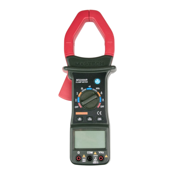
- Page 1 OPERATOR’S INSTRUCTION MANUAL DIGITAL CLAMP METER...
-
Page 2: Table Of Contents
CONTENTS PAGE Safety Information ..…………..……………..Safety Symbols .…..………….…...………….. Safety Precautions …..………...…………….. Maintenance .……………..…..…..………..General Description …….…..……………….. Front Panel Description ….…..…………..…. Clamp Meter Layout …………………………… Operating Instructions ………..……………. Specifications ………………..……….……..Auto Power Off ………………………………. Replacing The Battery .……..……………….. Accessories ……………….……………...…... - Page 3 CAUTION: Using this appliance in an environment with a strong radiated radio-frequency electromagnetic field (approximately 3V/m), may influence its measuring accuracy. The accuracy can be reduced to (12% of reading + 6 digits).
-
Page 4: Safety Information
SAFETY INFORMATION The digital clamp meter has been designed according to IEC1010 – 1 and IEC1010 – 2 – 032 concerning safety requirements electrical measuring instruments and hand – held current clamps with an overvoltage category (CAT II) and pollution 2. SAFETY SYMBOLS Important safety information, refer to the operating manual. -
Page 5: Safety Precautions
digital clamp meter complies with requirements of the following European Community Directives: 89/336/EEC (Electromagnetic Compatibility) 73/23/EEC (Low Voltage) as amended by 93/68/EEC (CE Marking). However, electrical noise or intense electromagnetic fields in the vicinity of the equipment may disturb the measurement circuit. - Page 6 The instructions in these warnings must be followed. • Always inspect your meter and test leads for any sign of damage or abnormality before every use. If any abnormal conditions exist (i.e. broken test leads, cracked cases, display not reading, etc.), do not attempt to take any •...
-
Page 7: Maintenance
3 MAINTENANCE • Before opening the case, always disconnect test leads from all energized circuits. • Never use the meter unless the back cover is in place and fastened completely. • Do not use abrasives or solvents on the meter. To clean it using a damp cloth and mild detergent only. - Page 8 4 Hold button When this button is pushed, the display will keep the last reading and “ ” symbol will appear on the LCD until pushing it again. Rotary switch This switch is used to select functions and to turn on / off the meter.
- Page 9 5 self-off. The light is on again, just push this button once. “VHz” jack This is positive input terminal for volt and frequency measurement connection is made to it using the red test lead. “COM” jack This is negative (ground) input terminal for all measurement modes except current.
- Page 10 6 AUTO Auto range indication. MANU fixation range indication Negative polarity indicates for digital reading. AC input indication DC input indication Low battery indication T-RMS True rms indication Auto power off indication Relative measurement indication Auto hold is active. Maximum reading displayed.
- Page 11 7 MAX button Press the button to select enter the Maximum value recording hold mode and the "MAX" symbol will appear on LCD. " MAX MIN" blink is current value. When the meter operates in Maximum value recording hold mode, push this button more than 1 seconds to disabled the function.
-
Page 12: Clamp Meter Layout
8 CLAMP METER LAYOUT... -
Page 13: Operating Instructions
9 OPERATING INSTRUCTIONS DC VOLTAGE MEASUREMENT Connect the red test lead to the “VHz” jack and the black lead to the “COM” jack. Set rotary switch at desired V position. Connect test leads across the source or load being measured. - Page 14 10 AC CURRENT MEASUREMENT Set the rotary switch at desired A~ position. Press the trigger to open transformer jaw and to clamp one conductor only, making sure that the jaw is firmly closed around the conductor. Read current value on LCD display. RESISTANCE MEASUREMENT Connect the red test lead to “”...
- Page 15 11 When checking in -circuit resistance, be sure the circuit under test has all power removed and that all capacitors have been discharged fully. For measuring resistance above 1M, the meter may take a few seconds to get stable reading. It is normal for high resistance measurements.
-
Page 16: Specifications
12 AUDIBLE CONTINUITY TEST Connect red test lead to “” jack, black test lead to “COM” jack. The polarity of red lead connection is positive “+”. Set range switch to “ ” position. Connect test leads to two points of circuit to be tested. - Page 17 13 Jaw opening capability: 55mm (Max conductor size) Power: 9V battery, NEDA 1604 6F22 006P Low battery indication: “ ” Appears on the display Operating environment : 0℃ to 40℃ Storage temperature: -10℃ to 50℃ Temperature coefficient: 0.1×specified accuracy /℃ ( <18℃ or >28℃ ) Altitude: 2000m Size: 282mm×104mm×47mm Weight: Approx.
- Page 18 14 AC VOLTAGE ( true rms., ac-coupled ) Range Resolution Accuracy 1.0% of rdg 5 digits 10mV 400V 0.1V 1.2 % of rdg 5 digits 750V Input Impedance: 10M Frequency range: 40Hz to 200Hz. Response: True rms. Rms. conversion with signal crest factor: 5.
- Page 19 15 RESISTANCE Range Resolution Accuracy 400 0.1 4k 1 1.5% of rdg 5 digits 40k 10 400k 0.1k 4M 1k 2.5% of rdg 10 digits 40M 10k Maximum Open Circuit Voltage: 0.5V Overload Protection: 250V dc or rms. ac for all ranges.
-
Page 20: Auto Power Off
16 AUTO POWER OFF To extend the battery life, Auto Power Off function is provided. After the meter no operations about 30 minutes, the meter will be turned off automatically. To turn it on need pushing the "REL" button only. REPLACING THE BATTERY WARNING Before attempting to open the case of battery, always... -
Page 21: Accessories
cover. 17 3. Remove battery and replace with a new equivalent 9 volt battery. 4. Replace the battery cover and reinstall the screw. ACCESSORIES • Operator’s instruction manual • Set of test leads • Gift box • 9 volt battery. NEDA 1604 6F22 006P type... - Page 22 18 HYS004994...
Need help?
Do you have a question about the MS2000R and is the answer not in the manual?
Questions and answers