Advertisement
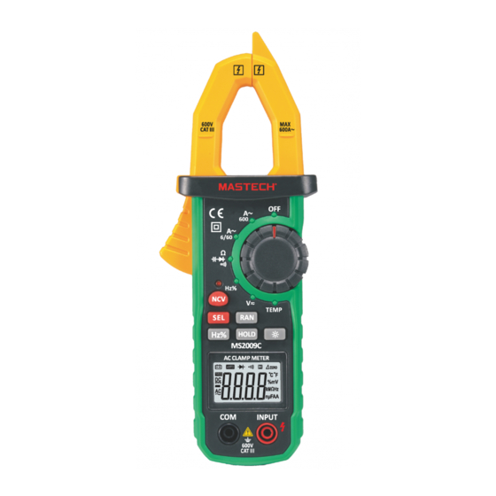
DIGITAL AC CLAMP METER
AUTO
T-RMS
DC
AC
MS2009C
CAT III
ZERO
C F
600 V
%mV
kM Hz
nμFAA
CONTENTS
Safety requirements................................1
Safety signs............................................1
Notes.......................................................1
Maintenance...........................................2
Overview.................................................3
Meter Indications.......................................3
Schematic Drawing For Panel .....................5
Instructions..............................................6
Accuracy Indicators...............................10
Technical Specifications ........................11
Replace Battery.....................................15
Replace tester leads...............................16
Accessories...........................................16
Advertisement
Table of Contents

Related Manuals for Mastech MS2009C


Summary of Contents for Mastech MS2009C
-
Page 1: Table Of Contents
MS2009C CONTENTS DIGITAL AC CLAMP METER Safety requirements........1 User Manual Safety signs..........1 Notes............1 Maintenance...........2 Overview..........3 Meter Indications........3 Schematic Drawing For Panel .....5 Instructions..........6 Accuracy Indicators.......10 Technical Specifications ......11 Replace Battery........15 Replace tester leads.......16 Accessories...........16 CAT III AUTO ZERO T-RMS 600 V kM Hz nμFAA... -
Page 2: User Manual
When the meter is measuring, don't touch the unused • Safety Requirements input terminal. The digital AC/DC clamp meter has been designed Be careful when measuring voltage greater than 60V • according to Safety Standard IEC61010-1 DC and 30V AC. Don't allow fingers to touch or block IEC61010-2-032 for electronic measuring instruments part of the probe. - Page 3 The meter is a safe and reliable digital clamp meter with stable performance. lt’s design is based on a large scale integrated circuit double integral A/D converter, with full measuring range of overload protection circuit. With a unique appearance, it is a special electrical meter with superior performance.
-
Page 4: Schematic Drawing For Panel
Schematic Drawing For Panel Instructions DC Voltage Measurement 1. Insert red probe to “INPUT” jack and insert black probe to “COM” jack. 2. Place function measuring range switch to DC voltage measuring range. Press “SEL” key, and connect the probe to the power source or load to be tested. - Page 5 Diode Test AC Current Measurement 1. Place function measuring range switch to AC Insert red probe to “INPUT” and insert black probe to current measuring range. “COM” jack. At this time, red probe polarity is “+”. 2. Press the trigger, open clamp head, clip the lead Place function measuring switch to position.
- Page 8 9.999nF 99.99nF 999.9nF 0.1nF 9.999μF 99.99μF 999.9μF...
- Page 9 Automatic Power-Off In order to extend the battery life, the meter has an automatic shutdown function. If there is no key operation or function measuring range change within 15 minutes, the meter power will disconnect automatically. Press “SEL” button to return the meter to the working state again.
-
Page 10: Accessories
If the sign “ ” appears, it means that the batteries should be replaced. Loosen the fixing screw of the battery cover and remove it. Replace the exhausted batteries with new ones. Put the battery cover back and fix it again to its origin form. Note: Do not reverse the polarity of the batteries.
Need help?
Do you have a question about the MS2009C and is the answer not in the manual?
Questions and answers