Table of Contents
Advertisement
Quick Links
CONTENTS
SAFETY INFORMATION...........................
SYMBOL EXPLANATION .........................
SAFETY PRECAUTIONS..........................
MAINTENANCE......................................
GENERAL DESCRIPTION........................
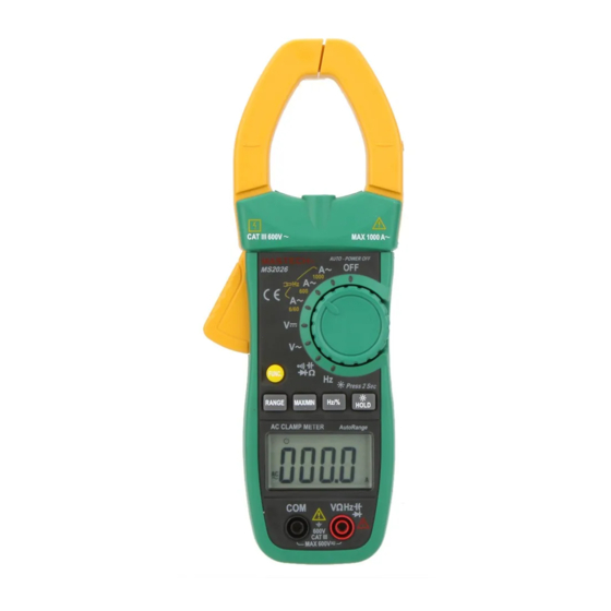
PANEL DESCRIPTION.............................
FORWARD LAYOUT................................
OPERATING INSTRUCTIONS...................
SPECIFICATIONS...................................
AUTO POWER OFF................................
REPLACING THE BATTERY.....................
ACCESSORIES......................................
PAGE
1
2
2
4
4
5
8
9
13
17
18
19
SAFETY INFORMATION
The digital clamp meter has been designed
according to IEC1010
1 and IEC1010
concerning safety requirements for electrical
measuring instruments and hand-held current
clamps with double insulation overvoltage category
1000V CAT II 600V CAT III and pollution 2.
This meter complies with the requirements of the
following European Community Directives:
89 / 336 / EEC (Electromagnetic Compatibility) and
73 / 23 / EEC (Low Voltage) as amended by 93 /
68 / EEC (CE Marking).
However, electrical noise or intense electromag-
netic fields in the vicinity of the equipment may
disturb the measurement circuit.
Measuring instruments will also respond to
unwanted signals that may be present within the
measurement circuit.
Users should exercise care and take appropriate
precautions to avoid misleading.
1
2
032
Advertisement
Table of Contents

Related Manuals for Mastech MS2026R


Summary of Contents for Mastech MS2026R
-
Page 1: Table Of Contents
SAFETY INFORMATION CONTENTS PAGE The digital clamp meter has been designed according to IEC1010 1 and IEC1010 concerning safety requirements for electrical SAFETY INFORMATION……………………... measuring instruments and hand-held current SYMBOL EXPLANATION ……………………. clamps with double insulation overvoltage category SAFETY PRECAUTIONS…………………….. 1000V CAT II 600V CAT III and pollution 2. -
Page 2: Symbol Explanation
SYMBOL EXPLANATION any sign of damage or abnormality before every use. If any abnormal conditions exist Important safety information, refer to the (i.e. broken test leads, cracked cases, operating manual. display not reading, etc.), do not attempt to Dangerous voltage may be present. take any measurements. -
Page 3: Maintenance
Otherwise, there is a radius lamp near the clamp, It MAINTENANCE is lighted in measuring current. ● Never touch exposed wiring, connections or any live circuit when attempting to take PANEL DESCRIPTION measurements. Transformer jaws ● Before opening the case, always disconnect Pick up the AC current flowing through the test leads from all energized circuits. - Page 4 LCD display autorange at first. To change to manual range, push this button once. When the meter operates in manual ranging mode, push this button to change range to the higher one and hold this button for more than 3 seconds to return to auto range mode FUNC.
-
Page 5: Forward Layout
FORWARD LAYOUT OPERATING INSTRUCTIONS DC VOLTAGE MEASUREMENT 1. Insert the black and red test leads into the COM and VHz input terminals respectively. 2. Set rotary switch at desired V position. Connect the test lead tips in parallel with the circuit to be measured. - Page 6 2. When checking in-circuit resistance, be sure AC CURRENT MEASUREMENT the circuit under test has all power removed Set the rotary switch at desired A~ position. and that all capacitors have been discharged Press the trigger to open transformer jaw fully.
-
Page 7: Specifications
diode. If the diode is reverse biased or there 4. Read the measure result from the display. is an open circuit the reading displayed will NOTE: be “OL”. The signal amplitude must also be greater than the sensitivity level. CAPACITANCE MEASUREMENT Determine that the amplitude level of the Insert the black and red test leads into the signal to be measured is not greater than the... - Page 8 DC VOLTAGE GENERAL Range Resolution Accuracy Maximum voltage: 1000V CATII 600V CATIII Altitude: 2000m (0.8%of rdg +5 digits) 10mV Display: LCD 5999 counts, 600V 0.1V Updates 2-3/sec (1.0%of rdg +2 digits) 1000V Ranging method: Auto/manual range mode Input Impedance: 10M Overload Protection: 1000V DC or 700V AC RMS “”...
-
Page 9: Auto Power Off
Frequency range: 50Hz to 60Hz FREQUENCY Overload Protection: Range Resolution Accuracy 120% ranges for 60 seconds max 40Hz 600Hz RESISTANCE (0.1% of rdg +1digit) 6kHz Range Resolution Accuracy 60kHz 10Hz 600 0.1 100kHz 0.1kHz 6k 1 Measurement range: (1.0% of rdg +3 digits) 60k... -
Page 10: Replacing The Battery
happen about 10 minutes, the meter will be turned Remove screws on the battery cover and off automatically. To turn it on, pushing the FUNC. open the cover. Button only. Remove the exhausted battery and replace with three new 1.5V size AAA batteries. REPLACING THE BATTERY Place battery cover and secure by a screw. - Page 11 OPERATOR’S INSTRUCTION MANUAL CLAMP METER HYS005013 A1...
Need help?
Do you have a question about the MS2026R and is the answer not in the manual?
Questions and answers