Table of Contents
Advertisement
Quick Links
Advertisement
Table of Contents

Related Manuals for Mastech MS2030B


Summary of Contents for Mastech MS2030B
- Page 1 MS2030B AC Digital Clamp Meter User’s Manual CAT III 600 V AUTO RS232...
-
Page 2: Table Of Contents
CONTENTS CONTENTS 1.Introduction ..........1 Resistance .................. 4.8 Diode Test 2.Safety Information.........1 ........... 4.9 Continuity Precautions ................. 4.10 Capacitance Safety Symbols............... 4.11 Temperature 3. Description...........4 ......4.12 Frequency/Duty Cycle ......... 3.1 Front Panel ....4.13 NCV (Non-Contact Voltage) Display .......... -
Page 3: Introduction
3. Ensure the meter works properly by testing a known 1.Introduction voltage first. If not working properly, have the meter WARNING serviced before using. Make sure to read and follow all safety procedures to 4. Never exceed the protection limit values indicated avoid electric shock and/or injury. -
Page 4: Safety Symbols
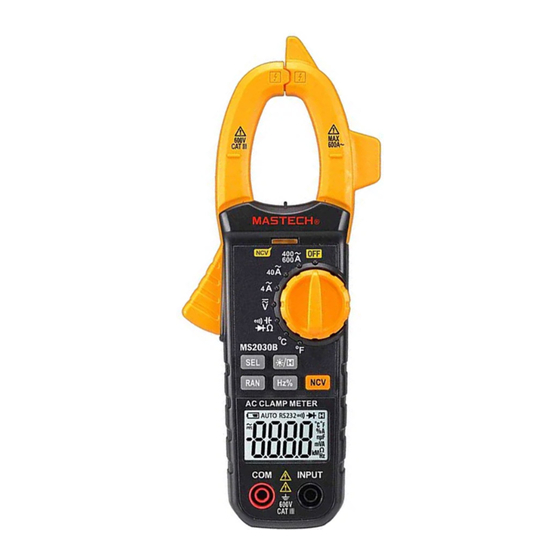
3. Description 2.2 Safety Symbols 3.1 Front Panel Note-Important safety information, refer to the instruction manual. Application around and removal from UNINSULATED HAZARDOUS LIVE conductors is permitted. Caution, possibility of electric shock Equipment protected throughout by double insulation or reinforced insulation. Conforms to UL STD. -
Page 5: Display
10. Range Button 1. Current Clamp Press the “RAN” button to switch to manual range. For measuring AC current. Each press increases the range and returns to the 2. Safety barrier lowest range when pressed in the highest range. Helps to keep hands from touching conductors while Hold the button to return to auto-range. -
Page 6: Using The Meter
3.2 Display 4. Using the Meter 4.1 Data Hold AUTO RS232 The data hold function will keep the current reading on the display. To activate data hold: 1. Press the “ ” button and the reading will be held on the display. The“ ”symbol appears. -
Page 7: Ac Voltage
4.5 AC Voltage 4.7 Resistance 1. Insert the red test lead in the “INPUT” jack and the 1. Turn off all power and discharge capacitors on the black lead in the “COM” jack. circuit under test. 2. Move the rotary switch to the“ ”position. -
Page 8: Diode Test
4.8 Diode Test 4.10 Capacitance 1. Turn off all power and discharge capacitors on the 1. Turn off all power and discharge capacitors on the circuit under test. circuit under test. 2. Insert the red test lead in the “INPUT” jack and the 2. -
Page 9: Ncv (Non-Contact Voltage)
4.13 NCV (Non-Contact Voltage) 5.2 Technical Specifications 1. Move the rotary switch to any position. Accuracy: ±(% of reading + digits), 1 year warranty. 2. Hold the “NCV” button and move the tip of the Ambient temp: 18°C~28°C, humidity: <75%. clamp close to the test object. - Page 10 5.2.2 AC Voltage 5.2.4 Resistance Range Accuracy Range Accuracy Resolution Resolution 400Ω 0.1Ω 400mV 0.1mV 4KΩ 1Ω ±(1.0% of reading+5 digits) ±(1.0% of reading+5 digits) 10mV 40KΩ 10Ω 400V 0.1V 400KΩ 0.1KΩ 600V 4MΩ 1KΩ ±(2.0% of reading+5 digits) - Input impedance: 10MΩ 40MΩ...
-
Page 11: Maintenance
5.2.10 Temperature 5.2.7 Capacitance Range Accuracy Resolution Range Accuracy Resolution -20~1000°C 1°C ±(4.0% of reading+5 digits) ±(3% of reading+3 digits) 5.0nF 0.001nF -4~1832°F 1°F 50nF 0.01nF 6.Maintenance 500nF 0.1nF ±(3.0% of reading+3 digits) 5.0µF WARNING 50µF 0.01µF Protection impairment if used in a manner not specified by the manufacturer. -
Page 12: Replacing The Batteries
6.2 Replacing The Batteries 7. Accessories 1 piece User’s manual WARNING To avoid electric shock, make sure that the test 1 pair Test leads leads have been clearly move away from the Type-K Thermocouple 1 piece circuit under measurement before opening the battery cover of the meter.
Need help?
Do you have a question about the MS2030B and is the answer not in the manual?
Questions and answers