
Subscribe to Our Youtube Channel
Related Manuals for Mastech MS2015B


Summary of Contents for Mastech MS2015B
- Page 1 MS2015B AC Digital Clamp Meter User Manual 6600 Temp FUNC HOLD MS2015B AC CLAMP METER NCV°F mVA°C nµmF MKΩHz...
-
Page 2: Table Of Contents
CONTENTS CONTENTS 1. Safety Information......1 4.5 Back light and Clamp Head light........14 1.1 Preliminary..........1 4.6 Automatic Power-Off.........15 1.2 Usage ............1 4.7 Measurement Preparation......16 1.3 Symbols...........3 4.8 Current Measurement ......16 1.4 Maintenance...........3 4.9 AC voltage Measurement......17 2. Description........4 4.10 DC Voltage Measurement......18 2.1 Part Name..........5 4.11 Measure Frequency........19 2.2 Switch, Button and... -
Page 3: Safety Information
大写 1. Safety Information 1.1.4 Probe should be in good condition. Before use, please check whether the probe insulation is Warning damaged, and whether metal wire is bare. 1.1.5 Use the probe table provided with the meter to Please particularly note that inappropriate use may cause shock or damage to the meter. -
Page 4: Symbols
1.2.11 Do not use the meter in explosive gas, vapor or 1.4.3 To avoid wrong readings causing electric shock, dusty environment. when“ ”appears on the meter display, 1.2.12 If you find any abnormal phenomena or failure replace the battery immediately. on the meter, stop using it immediately. -
Page 5: Part Name
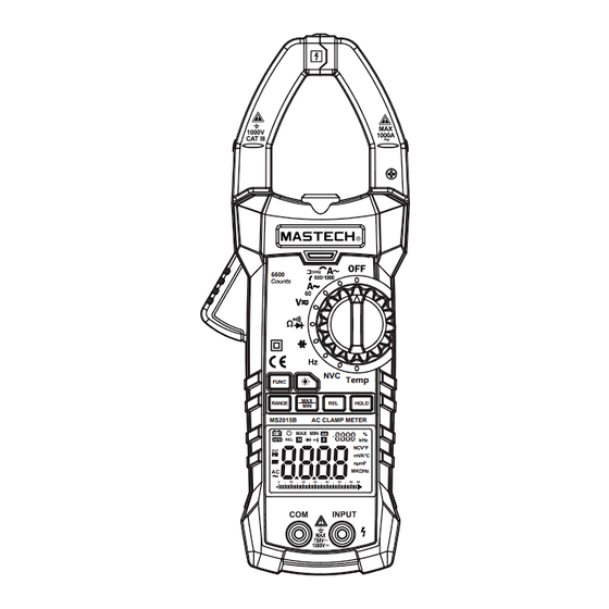
(8) LCD display (9) Common end jack (10) Input jack (11) Relative measurement button (REL) (12) Reading hold (HOLD) (13) Transfer switch 6600 (14) NCV indicator Temp 缺少 FUNC HOLD MS2015B AC CLAMP METER RANGE按 NCV°F mVA°C nµmF MKΩHz 键说明... -
Page 6: Switch, Button And Input Jack Description
2.2 Switch, Button And Input Jack Description Alternating Current FUNC button: used for measuring function switch. Direct Current button: used for backlight control. Diode RANGE button: used for switching between automatic measuring range and manual measuring range. Buzzer continuity MAX/MIN button: used for maximum/minimum display Automatic measuring range mode AUTO function. -
Page 7: Specifications
3. Specifications 3.2 Technical Indicators Environment temperature: 23±5°C, relative humidity The meter should be recalibrated under the condition (RH):<75% of 18°C~28°C, relative humidity less than 75% . 3.2.2 AC Current 3.1 General Measuring Resolution Accuracy 3.1.1 Auto measuring range. 0.01A 3.1.2 Full measuring range overload protection ±(2.5% of reading+6 digits) 660A... - Page 8 Note: 3.2.5 Frequency In the small voltage measuring range, when the probe Measuring range Accuracy Resolution is not connected with the circuit to be tested, and the 66.00Hz 0.001Hz meter may have fluctuating readings, which is normal and caused by the meter's high sensitivity. When the 660.0Hz 0.01Hz meter is connected with the circuit to be tested, you will...
-
Page 9: Operating Guidance
3.2.8 Circuit Continuity Test 4.2 Relative measurement 4.2.1 Relative measurement only can be used to Measuring range Accuracy Resolution measure current, voltage, resistance, capacitance If the resistance of circuit to and temperature. be measured is less than 4.2.2 Press the “REL” key to enter relative 0.1Ω... -
Page 10: Back Light And Clamp Head Light
4.5 Back light and clamp head light 4.7 Measurement preparation 4.7.1 Turn the transfer switch to turn on the power. 4.5.1 In the process of measurement, if ambient light is too dark to read, press “ ”key to turn on the When battery voltage is low (about <7V), LCD backlight. -
Page 11: Ac Voltage Measurement
4.9 AC voltage measurement 4.10 DC voltage measurement Warning Warning Electric shock hazard. Electric shock hazard. Pay special attention to avoid shock when Pay special attention to avoid shock when measuring high voltage. measuring high voltage. Don't input voltage more than DC1000V RMS. Don't input voltage more than AC600V RMS. -
Page 12: Measure Frequency
4.11 Measure frequency 4.13 Diode Test 4.13.1 Insert black probe to the COM jack and insert Warning red probe to the INPUT jack. Electric shock hazard. 4.13.2 Place measuring switch in positionΩ Pay special attention to avoid shock when 4.13.3 Press the “FUNC” key to switch to measuring measuring high voltage. -
Page 13: Capacitance Measurement
Note: 5. Maintenance If the probe is open or circuits resistance to be tested is 5.1 Replace battery more than 400Ω , the display will show “0L”. Warning 4.15 Capacitance measurement Before opening the meter battery cover, the probe should be remove d from the circuit to be Warning measured to avoid electric shock.
Need help?
Do you have a question about the MS2015B and is the answer not in the manual?
Questions and answers