
Related Manuals for Mastech MS2026


Summary of Contents for Mastech MS2026
- Page 1 MS2026 MS2026R DIGITAL CLAMP METER Use’s Manual MS2026 FUNC . RANGE MAX/MIN Hz/% HOLD Auto Range AC CLAMP METER AUTO MAX MIN μnF kMΩ CAT III 600 V...
-
Page 2: Table Of Contents
CONTENTS CONTENTS 1. Safety Information….......1 4.5 Switching Functions......16 4.6 Back Light and 1.1 Preliminary........1 Clamp Lighting Bulb......17 1.2 During Use.........2 4.7 Auto Power Off........18 1.3 Symbols..........3 4.8 Preparing for Measurement....18 1.4 Maintenance........3 4.9 Measuring AC Current......18 2. Description….........4 4.10 Measuring AC Voltage.......19 2.1 Names of Parts........5 4.11 Measuring DC Voltage.......20 2.2 Switch, Buttons and Input Jacks...7... -
Page 3: Safety Information
1. Safety Information 1.1.5 Use the test leads supplied to ensure operation safety. If required, they must be replaced with test WARNING leads of the same model or class. BE EXTREMELY CAREFUL WHEN USING THIS 1.2 During Use METER. Improper use of this device can result in electric shock or destruction of the meter. - Page 4 Note-Important safety information, refer to the instruction manual. Application around and removal from UNINSULATED HAZARDOUS LIVE conductors is permitted. Caution, possibility of electric shock Equipment protected throughout by double insulation or reinforced insulation. Earth (ground) TERMINAL CAT III: MEASUREMENT CATEGORY III is applicable to test and measuring circuits connected to the distribution part of the building's low-voltage MAINS installation.
-
Page 5: Symbols
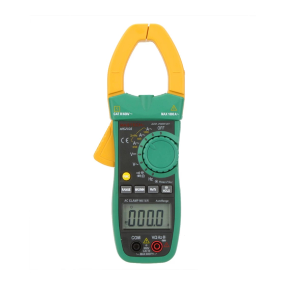
(7) manual Button (RANGE) (8) Liquid Crystal Display (LCD) (9) COM Jack (10) Input Jack (11) Hz/Duty Switch Button (Hz/%) MS2026 (12) Reading Hold/Back Light Button (HOLD/B.L) (13) Rotary selector (14) OFF - power switch (15) “+” Symbol (16) “-” Symbol FUNC . -
Page 6: Switch, Buttons And Input Jacks
2.2 Switch, Buttons and Input Jacks 2.3 LCD (Liquid-crystal display) HOLD/B.L Button - For holding the reading or control back light AUTO MAX MIN FUNC Button μnF - For switching among measuring functions RAN Button kMΩ - The key is the Auto/Manual measurement key. Hz/% Button - For switching between frequency and duty measuring ALTERNATING CURRENT... -
Page 10: Operation Instruction
4. Operation Instruction 4.4 Switching Maximum or Minimum Value 4.4.1 At all ranges, press the “MAX/MIN” button 4.1 Holding Readings one time, the meter can be set to maximum 4.1.1 Press the “HOLD/B.L” button to hold the readings value measuring mode; press the button twice, while taking measurement and the value on the the meter can be set to minimum value display will be held. -
Page 12: Measuring Ac Voltage
Note: 4.11 Measuring DC Voltage 1) Do not put more than one cable into the jaw during test, WARNING otherwise incorrect test value might be obtained. Beware of Electrocution. 2) For optimum results, center the conductor in the jaw. Pay special attention to avoid electric shock 3) At the manual range mode, when only 'OL' is shown on when measuring high voltage. -
Page 15: Measuring Resistance
4.13.3 By HZ/DUTY range: 4.14 Measuring Resistance WARNING WARNING Beware of Electrocution. Pay special attention Beware of Electrocution. to avoid electric shock when measuring high When measuring in-circuit resistance, make voltage. Do not input the voltage which more sure that the power of the circuit under test than 250V rms AC. -
Page 17: Measuring Capacitance
4.17 Measuring Capacitance 5. Maintenance 5.1 Replacing The Batteries WARNING WARNING Beware of Electrocution. To avoid electric shock, make sure that the test To avoid electric shock, make sure that the leads have been clearly move away from the capacitors have been fully discharged before circuit under measurement before opening the measuring the capacitance of a capacitor. -
Page 18: Accessories
6. Accessories 1) Test Leads: Electric Ratings 1000V 10A 1 pair (set) 2) Operating Manual 1 copy 3) 1.5V AAA Battery 3 piece 00-05-3033...
Need help?
Do you have a question about the MS2026 and is the answer not in the manual?
Questions and answers