SMA SUNNY TRIPOWER CORE1 Operating Manual
For decentralized rooftop and ground-based pv systems
Hide thumbs
Also See for SUNNY TRIPOWER CORE1:
- Replacement manual (252 pages) ,
- Quick reference manual (150 pages) ,
- Operating manual (114 pages)

Related Manuals for SMA SUNNY TRIPOWER CORE1


Summary of Contents for SMA SUNNY TRIPOWER CORE1
- Page 1 Operating manual SUNNY TRIPOWER CORE1 W E R R I P O N Y T S U N ENGLISH STP50-40-BE-en-12 | Version 1.2...
- Page 2 The information contained in these documents is property of SMA Solar Technology AG. Any publication, whether in whole or in part, requires prior written approval by SMA Solar Technology AG. Internal reproduction used solely for the purpose of product evaluation or other proper use is allowed and does not require prior approval.
- Page 3 SMA Solar Technology AG Table of Contents Table of Contents Information on this Document..........Validity ........................Target Group......................Structure........................Types of warning message..................Symbols ........................Typographies......................Nomenclature......................Additional Information ....................Safety ..................Intended Use ......................Safety Information...................... Scope of Delivery ..............12 Product Overview ..............
- Page 4 Configuring the Modbus Function................62 Setting the Tripping Threshold of the Residual-Current Device........ 63 Configuring Feed-In Management................63 Setting SMA OptiTrac Global Peak ................. 64 Activating the Receipt of Control Signals (Only for Italy)........64 9.10 Activating String-Failure Detection ................65 9.11...
- Page 5 SMA Solar Technology AG Table of Contents 12.2 LED Signals ......................... 85 12.3 Forgotten Password....................86 12.4 Checking the PV System for Ground Faults.............. 87 12.5 Updating the Firmware ....................90 13 Decommissioning the Inverter..........92 14 Technical Data ................96 15 Accessories ................101...
-
Page 6: Information On This Document
Information on this Document Validity This document is valid for the following device types: • STP 50-40 (Sunny Tripower CORE1) Target Group This document is intended for qualified persons and end users. Only qualified persons are allowed to perform the activities marked in this document with a warning symbol and the caption "Qualified person". -
Page 7: Symbols
Complete designation Designation in this document Sunny Tripower CORE1 Inverter, product Additional Information Links to additional information can be found at www.SMA-Solar.com: Document title Document type "Parameters and Measured Values" Technical Information Overview of All Inverter Operating Parameters and Their Configura-... - Page 8 Registration in Sunny Portal and setting or changing operating pa- rameters of the inverter "SMA Modbus® Interface" Technical Information Information on the commissioning and configuration of the SMA Modbus interface "SunSpec® Modbus® Interface" Technical Information Information on the commissioning and configuration of the SunSpec Modbus interface "Efficiency and Derating"...
-
Page 9: Safety
All components must remain within their permitted operating ranges and their installation requirements at all times. The product must only be used in countries for which it is approved or released by SMA Solar Technology AG and the grid operator. - Page 10 2 Safety SMA Solar Technology AG DANGER Danger to life due to high voltages of the PV array When exposed to light, the PV array generates dangerous DC voltage, which is present in the DC conductors and the live components of the inverter. Touching the DC conductors or the live components can lead to lethal electric shocks.
- Page 11 SMA Solar Technology AG 2 Safety NOTICE Damage to the type label due to the use of cleaning agents • If the inverter is dirty, clean the enclosure, the enclosure lid, the type label and the LEDs with a damp cloth and clear water only.
-
Page 12: Scope Of Delivery
3 Scope of Delivery SMA Solar Technology AG Scope of Delivery Check the scope of delivery for completeness and any externally visible damage. Contact your distributor if the scope of delivery is incomplete or damaged. Figure 1: Components included in the scope of delivery... -
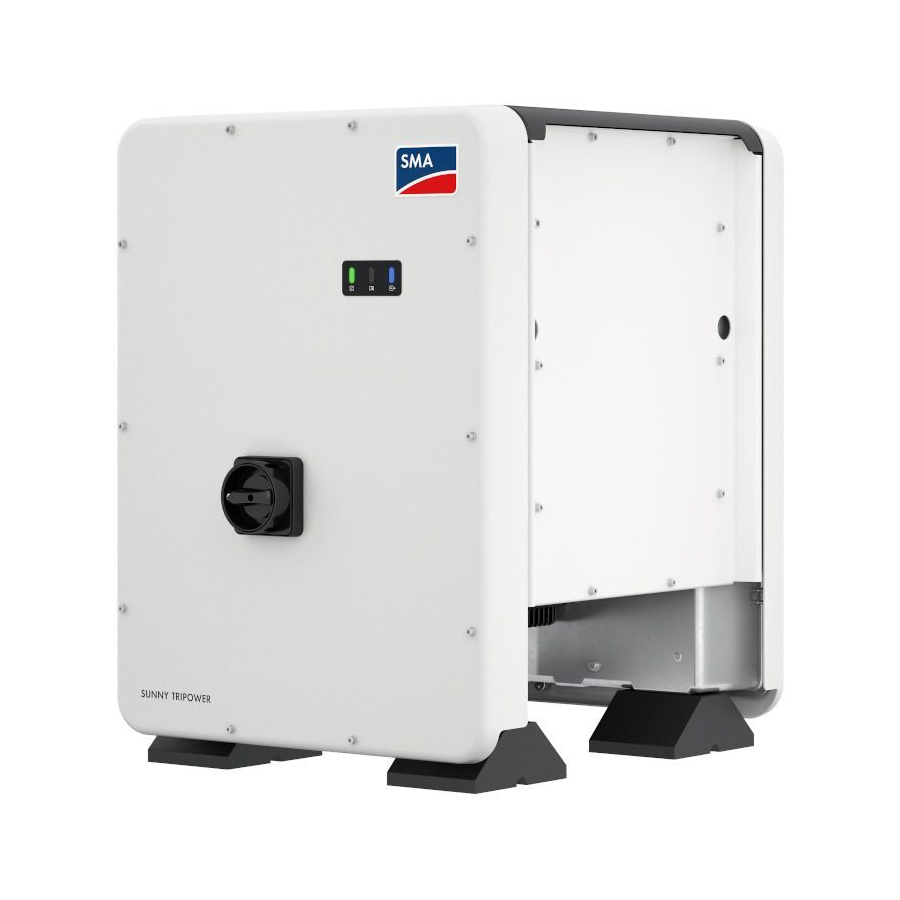
Page 13: Product Overview
SMA Solar Technology AG 4 Product Overview Product Overview Product Description Figure 2: Design of the Sunny Tripower Position Designation Cover AC Connection Unit DC Connection Unit LEDs The LEDs indicate the operating state of the inverter. Cable glands for data cables... - Page 14 4 Product Overview SMA Solar Technology AG Position Designation Additional label with details for registration in Sunny Portal and WLAN password: • Identification key (PIC) for registration in Sunny Portal • Registration ID (RID) for registration in Sunny Portal • WLAN password (WPA2-PSK) for the direct connection to the user...
-
Page 15: Interfaces And Functions
SMA Speedwire The product is equipped with SMA Speedwire as standard. SMA Speedwire is a type of communication based on the Ethernet standard. SMA Speedwire is designed for a data transfer rate of 100 Mbps and enables optimum communication between Speedwire devices within systems. - Page 16 The product is equipped with a Modbus interface. The Modbus interface is deactivated by default and must be configured as needed. The Modbus interface of the supported SMA products is designed for industrial use – via SCADA systems, for example – and has the following tasks: •...
-
Page 17: Multifunction Relay
Antenna Extension Kit can be retrofitted. SMA I/O modules The SMA I/O Module enables the inverter to perform grid management services (for information on installation and connection, see the manual of the SMA I/O Module). The SMA I/O Module can be retrofitted. SMA Sensor Module The SMA Sensor Module has different interfaces for connecting various sensors (i.e. -
Page 18: Mounting
5 Mounting SMA Solar Technology AG Mounting Requirements for Mounting Requirements for the Mounting Location: WARNING Danger to life due to fire or explosion Despite careful construction, electrical devices can cause fires. • Do not mount the product in areas containing highly flammable materials or gases. - Page 19 SMA Solar Technology AG 5 Mounting Dimensions for mounting: 79.4 79.4 M8x14/17+1 M8x14/17+1 46.2 46.2 Figure 3: Position of the anchoring points(Dimensions in mm) Structural Stability: ☐ When mounting with feet or profile rails, the width of one foot or the profile rail must be at least 175 mm to ensure structural stability.
- Page 20 ☐ When mounting with profile rails, an attachment or fixation by loading is required. When mounting with profile rail, SMA Solar Technology AG recommends to bolt the profile rail e.g. to the profile of the module frame or to attach a sheet metal (which can be weighted with stones or with sandbags) at the profile rails.
-
Page 21: Mounting The Inverter
SMA Solar Technology AG 5 Mounting 1 0 0 0 ( 3 9 . 3 ( 3 . 9 4 1 0 0 1 0 0 0 1 0 0 0 ( 3 5 . 4 ( 3 5 . 4 ( 3 9 . - Page 22 5 Mounting SMA Solar Technology AG Procedure: 1. Tighten every foot with two M8x40 hexagon screws and two washers on the two external taps (M8x14) on the underside of the inverter (torque: 16 Nm). 2. Screw all four transport handles as far as they will go into the taps on the right- and left-hand side until they lie flush with the enclosure.
- Page 23 SMA Solar Technology AG 5 Mounting 6. Remove all four transport handles from the taps. If necessary, insert a screwdriver into the holes on the transport handle and use the screwdriver to remove the transport handle. Operating manual STP50-40-BE-en-12...
-
Page 24: Electrical Connection
6 Electrical Connection SMA Solar Technology AG Electrical Connection Safety during Electrical Connection DANGER Danger to life due to high voltages of the PV array When exposed to light, the PV array generates dangerous DC voltage, which is present in the DC conductors and the live components of the inverter. -
Page 25: Overview Of The Connection Area
SMA Solar Technology AG 6 Electrical Connection Overview of the Connection Area Figure 7: Connection areas of the inverters' AC Connection Unit and DC Connection Unit Position Designation Slots for AC surge protection devices Terminal blocks for AC connection Bridge between N and enclosure... - Page 26 • Use a load-break switch or circuit breaker as a load disconnection unit (for information and design examples, see the Technical Information "Circuit Breaker" at www.SMA-Solar.com). ☐ In PV systems with multiple inverters, protect each inverter with a separate three-phase circuit breaker.
-
Page 27: Connecting The Inverter To The Utility Grid
500 mA or higher (for details on selecting a residual-current device, see the Technical Information ""Criteria for Selecting a Residual-Current Device"" at www.SMA-Solar.com). Residual-current devices with a tripping threshold < 500 mA can be used. The tripping threshold of 300 mA must not be undershot. - Page 28 6 Electrical Connection SMA Solar Technology AG 6. Thread the AC cable through the cable gland into the AC Connection Unit. If necessary, slightly loosen the swivel nut of the cable gland. 7. Dismantle the AC cable. 8. Strip off the insulation of L1, L2, L3, N and PE by 30 mm.
-
Page 29: Dc Connection
SMA Solar Technology AG 6 Electrical Connection DC Connection 6.4.1 Requirements for the DC Connection Requirements for the PV modules per input: ☐ All PV modules must be of the same type. ☐ All PV modules must be aligned and tilted identically. - Page 30 6 Electrical Connection SMA Solar Technology AG ☐ Qty single wires: minimum 7 ☐ Nominal voltage: minimum 1000 V ☐ Using bootlace ferrules is not allowed. DANGER Danger to life due to high voltages on the DC conductors When exposed to sunlight, the PV array generates dangerous DC voltage which is present in the DC conductors.
-
Page 31: Connecting The Pv Array
SMA Solar Technology AG 6 Electrical Connection ☑ The stranded wire can be seen inside the clamping bracket chamber. ✖ The stranded wire cannot be seen in the chamber? The cable is not correctly in place. • Release the clamping bracket. To do so, insert a screwdriver (blade width: 3.5 mm) - Page 32 6 Electrical Connection SMA Solar Technology AG NOTICE Damage to the DC connectors due the use of contact cleaner of other cleaning agents Some contact cleaners or other cleaning agents may contain substances that decompose the plastic of the DC connectors.
- Page 33 SMA Solar Technology AG 6 Electrical Connection 5. Check whether the DC connectors have the correct polarity. If the DC connector is equipped with a DC cable of the wrong polarity, the DC connector must be reassembled. The DC cable must always have the same polarity as the DC connector.
-
Page 34: Disassembling The Dc Connectors
6 Electrical Connection SMA Solar Technology AG NOTICE Damage to the inverter due to moisture ingress If the electrical connection is not made immediately after the installation, the inverter is not sealed and moisture can penetrate the inverter. The inverter is only sealed if the DC connectors are connected to the inverter with the DC conductors or with sealing plugs. -
Page 35: Connecting The Multifunction Relay
SMA Solar Technology AG 6 Electrical Connection Procedure: 1. Release and remove all DC connectors. To do this, insert a flat-blade screwdriver or an angled screwdriver (blade width 3.5 mm) into one of the slide slots and pull the DC connectors out in a downward direction. -
Page 36: Operating Modes Of The Multifunction Relay
6 Electrical Connection SMA Solar Technology AG Procedure Connect to the multifunction relay according to the operat- Section 6.5.3, page 36 ing mode and the associated connection variant. and Section 6.5.4, page 40 After commissioning the inverter, change the operating Section 9.4, page 61 mode of the multifunction relay, if necessary. - Page 37 SMA Solar Technology AG 6 Electrical Connection Operating mode Connection option Connecting the external fan (see fan documentation) Fan control (FanCtl) Switching status grid re- Reporting the switching status of the grid relay lay (GriSwCpy) Operating manual STP50-40-BE-en-12...
- Page 38 6 Electrical Connection SMA Solar Technology AG Using the Multifunction Relay as a Fault Indicator Contact You can use the multifunction relay as a fault indicator contact and have an error or smooth operation of the inverter displayed or signaled via a suitable display device. You can connect multiple inverters to one fault indicator or operation indicator, as needed.
- Page 39 SMA Solar Technology AG 6 Electrical Connection Controlling loads via the multifunction relay or charging batteries depending on the power production of the PV system The multifunction relay can control loads or charge batteries power-dependently. To enable this function, you must connect a contactor (K1) to the multifunction relay. The contactor (K1) switches the operating current for the load on or off.
-
Page 40: Connection To The Multifunction Relay
6 Electrical Connection SMA Solar Technology AG Reporting the switching status of the grid relay The multifunction relay can trip a signal to the grid operator as soon as the inverter connects to the utility grid. To enable this function, the multifunction relays of all inverters must be connected in parallel. - Page 41 SMA Solar Technology AG 6 Electrical Connection Procedure: DANGER Danger to life due to high voltages • Disconnect the inverter from all voltage sources (see Section 10, page 69). 2. If the enclosure lid of the DC Connection Unit is closed, remove it as follows: Unscrew all ten screws with a Torx screwdriver (TX 25) and remove the...
-
Page 42: Connecting The Network Cables
6 Electrical Connection SMA Solar Technology AG Connecting the Network Cables DANGER Danger to life due to electric shock Overvoltages (e. g. in the case of a flash of lightning) can be further conducted into the building and to other connected devices in the same network via the network cable if there is no overvoltage protection. - Page 43 SMA Solar Technology AG 6 Electrical Connection 2. If the enclosure lid of the DC Connection Unit is closed, remove it as follows: Unscrew all ten screws with a Torx screwdriver (TX 25) and remove the enclosure lid carefully forward. 3. Set the screws and the enclosure lid aside and store safely.
-
Page 44: Commissioning
Section 8.2, page 53 Select the inverter configuration option. Please note that Section 7.4, page 46 the SMA Grid Guard code (a charge is levied for this code) for changing the grid-relevant parameters must be available after completion of the first ten feed-in hours or installation assistant (see "Application for the SMA Grid Guard code"... -
Page 45: Starting The Self-Test (For Italy Only)
SMA Solar Technology AG 7 Commissioning Procedure: 1. Position the enclosure lid of the AC connection unit on the AC connection unit and first tighten the upper-left and lower-right screws, and then the remaining screws crosswise using a Torx screwdriver (TX 25) (torque: 6 Nm). -
Page 46: Selecting A Configuration Option
7 Commissioning SMA Solar Technology AG The self-test changes the upper and lower disconnection values for each protective function on a linear basis for frequency monitoring and voltage monitoring. As soon as the measured value exceeds the permitted disconnection threshold, the inverter disconnects from the utility grid. In this way, the inverter determines the reaction time and checks itself. - Page 47 On the Configuring the Inverter page, different configuration options are available to choose from. Select one of the options and proceed for the selected option as described below. SMA Solar Technology AG recommends carrying out the configuration with the installation assistant. This way, you ensure that all relevant parameters are set for optimal inverter operation.
- Page 48 7 Commissioning SMA Solar Technology AG Configuring the Installation Assistant (Recommended) Figure 14: Layout of the installation assistant (example) Position Designation Description Configuration steps Overview of the installation assistant steps. The number of steps depends on the type of device and the additionally installed modules.
- Page 49 SMA Solar Technology AG 7 Commissioning Procedure: 1. Select the configuration option Manual Configuration. ☑ The Device Parameters menu on the user interface will open and all available parameter groups of the inverter will be displayed. 2. Select [Edit parameters].
-
Page 50: Using The Inverter User Interface
☐ JavaScript must be enabled in the web browser of the end device. ☐ The SMA Grid Guard code of the Installer must be available for the changing of grid-relevant settings after completion of the first ten feed-in hours or installation assistant (see "Application for SMA Grid Guard Code"... -
Page 51: Establishing A Connection Via Wlan In The Local Network
2. If your end device has not a WPS function: • Search for WLAN networks with your end device. • Select the SSID of the inverter SMA[serial number] in the list with the found WLAN networks. • Enter the inverter WLAN password. Within the first ten feed-in hours and prior to completing the configuration by means of the installation assistant, you must use the standard WLAN password SMA12345. -
Page 52: Establishing A Connection Via Ethernet In The Local Network
☐ The respective latest version of one of the following web browsers must be installed: Chrome, Edge, Firefox, Internet Explorer or Safari. ☐ The SMA Grid Guard code of the Installer must be available for the changing of grid-relevant settings after completion of the first ten feed-in hours or installation assistant (see "Application for SMA Grid Guard Code"... -
Page 53: Logging In And Out Of The User Interface
☐ The respective latest version of one of the following web browsers must be installed: Chrome, Edge, Firefox, Internet Explorer or Safari. ☐ The SMA Grid Guard code of the Installer must be available for the changing of grid-relevant settings after completion of the first ten feed-in hours or installation assistant (see "Application for SMA Grid Guard Code"... - Page 54 8 Using the Inverter User Interface SMA Solar Technology AG 4. In the Repeat password field, enter the new password again. 5. Select Login. ☑ The Configuring the Inverter page opens. Log in as the User or Installer 1. In the drop-down list Language, select the desired language.
-
Page 55: Start Page Design Of The User Interface
SMA Solar Technology AG 8 Using the Inverter User Interface Start Page Design of the User Interface Figure 15: Start page design of the user interface (example) Operating manual STP50-40-BE-en-12... -
Page 56: Device Configuration
User settings Provides the following functions, depending on the user group logged in: • Starting the installation assistant • SMA Grid Guard login • Logout Help Provides the following functions: • Displaying information on Open Source licenses used • Link to the website of SMA Solar Technology AG STP50-40-BE-en-12 Operating manual... -
Page 57: Displaying And Downloading The Stored Data
SMA Solar Technology AG 8 Using the Inverter User Interface Posi- Designation Description tion Status bar Displays the following information: • Inverter serial number • Inverter firmware version • IP address of the inverter within the local network and/or IP address of the inverter during WLAN connection •... -
Page 58: Changing The Password
8 Using the Inverter User Interface SMA Solar Technology AG Procedure: 1. Activate the user interface (see Section 8.1, page 50). 2. Log into the user interface (see Section 8.2, page 53). 3. Select the menu Data. 4. Select the folder Data. 5. To call up the data, select the respective folder and click on the required file. -
Page 59: Configuration Of The Inverter
3. Call up the menu Device Parameters. 4. Select [Edit parameters]. 5. Log in using the SMA Grid Guard code to change those parameters designated by a lock (only for installers): • Select the menu User Settings (see Section 8.3, page 55). -
Page 60: Starting The Installation Assistant
☐ When configuring after completion of the first ten feed-in hours or after exiting the installation assistant, the SMA Grid Guard code must be available in order to change the grid-relevant parameters (see "Application for SMA Grid Guard Code" at www.SMA-Solar.com). A charge is levied for this code. -
Page 61: Configuring The Country Data Set
SMA Solar Technology AG 9 Configuration of the Inverter Configuring the Country Data Set By default, the inverter is set to a universally valid country data set. You can adjust the country data set for the installation site retroactively. The country data set must be set correctly. -
Page 62: Configuring The Modbus Function
For information on commissioning and configuration of the Modbus interface, see the Technical Information "SMA Modbus® Interface" or in the Technical Information "SunSpec® Modbus® Interface" at www.SMA-Solar.com. For information on which Modbus registers are supported, see the Technical Descriptions "SMA Modbus® Interface" or "SunSpec® Modbus® Interface" at www.SMA-Solar.com. STP50-40-BE-en-12... -
Page 63: Setting The Tripping Threshold Of The Residual-Current Device
– In order to deactivate the Modbus interface, reset the inverter to default settings or deactivate the activated parameter again. Procedure: • Activate the Modbus interface and adjust the communication ports if necessary (see the technical information "SMA Modbus® Interface" or "SunSpec® Modbus® Interface" at www.SMA-Solar.com). Setting the Tripping Threshold of the Residual-Current Device If a residual-current device with a tripping threshold of < 500 mA is used, you must change the... -
Page 64: Setting Sma Optitrac Global Peak
Setting SMA OptiTrac Global Peak For partially shaded PV modules, you should set the interval at which the inverter is to optimize the MPP of the PV system. If you do not want to use SMA OptiTrac Global Peak feature, you can deactivate the feature. -
Page 65: Activating String-Failure Detection
SMA Solar Technology AG 9 Configuration of the Inverter 2. In the field Application ID, enter the application ID of the grid operator gateway. You will receive this value from your grid operator. You can enter a value between 0 and 16384. The value 16384 indicates "deactivated". -
Page 66: Switching The Dynamic Power Display Off
SMA Solar Technology AG Requirements: ☐ The SMA Grid Guard code must be available (see "Application for SMA Grid Guard Code" at www.SMA-Solar.com). A charge is levied for this code. ☐ Changes to grid-relevant parameters must be approved by the responsible grid operator. -
Page 67: Activate Wps Function
SMA Solar Technology AG 9 Configuration of the Inverter Procedure: • To switch off the direct connection in the parameter group PV system communication > WLAN, select the parameter Soft-access-point is turned on and set this to No. • To switch off the connection in the local network in the parameter group PV system communication >... - Page 68 9 Configuration of the Inverter SMA Solar Technology AG Activating the WPS function for direct connection to the end device. • Activate the WPS function on the inverter. To do this, tap twice in succession on the enclosure lid of the DC connection unit next to the LEDs.
-
Page 69: Disconnecting The Inverter From Voltage Sources
SMA Solar Technology AG 10 Disconnecting the Inverter from Voltage Sources 10 Disconnecting the Inverter from Voltage Sources Prior to performing any work on the inverter, always disconnect it from all voltage sources as described in this section. Always adhere to the prescribed sequence. - Page 70 10 Disconnecting the Inverter from Voltage Sources SMA Solar Technology AG 9. Unscrew all ten screws of the enclosure lid of the AC connection unit using a Torx screwdriver (TX 25) and remove the enclosure lid towards the front. 10. Set the screws and the enclosure lid aside and store safely.
-
Page 71: Cleaning The Inverter
SMA Solar Technology AG 11 Cleaning the Inverter 11 Cleaning the Inverter NOTICE Damage to the type label due to the use of cleaning agents • If the inverter is dirty, clean the enclosure, the enclosure lid, the type label and the LEDs with a damp cloth and clear water only. -
Page 72: Troubleshooting
12 Troubleshooting SMA Solar Technology AG 12 Troubleshooting 12.1 Event Messages Event number Message, cause and corrective measures Grid fault The grid voltage or grid impedance at the connection point of the inverter is too high. The inverter has disconnected from the utility grid. - Page 73 SMA Solar Technology AG 12 Troubleshooting Event number Message, cause and corrective measures Grid fault The inverter has disconnected from the utility grid. A stand-alone grid or a very large change in the power frequency was detected. Corrective measures: • Check the grid connection for significant short-term frequency fluctuations.
- Page 74 12 Troubleshooting SMA Solar Technology AG Event number Message, cause and corrective measures Waiting for grid voltage > Grid failure > Check AC circuit breaker The AC cable is not correctly connected or the country data set is not correctly configured.
- Page 75 SMA Solar Technology AG 12 Troubleshooting Event number Message, cause and corrective measures 3501 Insulation failure > Check generator The inverter has detected a ground fault in the PV array. Corrective measures: • Check the PV system for ground faults (see Section 12.4, page 87).
- Page 76 Corrective measures: • Ensure that the parameters are set correctly. • Ensure that the SMA Grid Guard code is available. 7106 Update file defect. The update file is defective. The update failed. The inverter continues feeding power into the grid.
- Page 77 SMA Solar Technology AG 12 Troubleshooting Event number Message, cause and corrective measures 7303 Update main CPU failed The cause must be determined by the Service. Corrective measures: • Contact the Service (see Section 16 "Contact", page 102). 7320 The device with serial number [xx] was successfully updated to firmware version [xxx].
- Page 78 12 Troubleshooting SMA Solar Technology AG Event number Message, cause and corrective measures 7347 Incompatible file The configuration file is not suitable for this inverter. Corrective measures: • Ensure that the selected configuration file is suitable for this inverter. • Retry import.
- Page 79 SMA Solar Technology AG 12 Troubleshooting Event number Message, cause and corrective measures 7356 Update of the WebUI not successful The update of the inverter user interface failed. Corrective measures: • Retry update. • If this message is displayed again, contact the Service (see Section 16 "Contact", page 102).
- Page 80 9003 Grid parameter locked Changes to the grid parameters are now blocked. In order to be able to make changes to the grid parameters, from now on you must log in using the SMA Grid Guard code. 9005 Changing of grid parameters not possible > Ensure DC supply This error can have the following causes: •...
- Page 81 SMA Solar Technology AG 12 Troubleshooting Event number Message, cause and corrective measures 10110 Time synchronization failed: |xx| No time information could be called up from the set NTP server. Corrective measures: • Ensure that the NTP server was configured correctly.
- Page 82 12 Troubleshooting SMA Solar Technology AG Event number Message, cause and corrective measures 10251 [Interface]: communication status goes to [OK / Warning / Error / Not connected] The communication status to the network switch or DHCP server (router) has changed. An additional error message may be displayed.
- Page 83 SMA Solar Technology AG 12 Troubleshooting Event number Message, cause and corrective measures 10255 [Interface]: Network load OK The network load has returned to a normal range after being busy. 10282 [User group]-Login via [protocol] locked After several incorrect login attempts, login has been blocked for a limited time.
- Page 84 12 Troubleshooting SMA Solar Technology AG Event number Message, cause and corrective measures 10286 WLAN connection lost The inverter has lost WLAN connection to the selected network. Corrective measures: • Ensure that the WLAN router or WLAN Access Point is still active.
-
Page 85: Led Signals
SMA Solar Technology AG 12 Troubleshooting Event number Message, cause and corrective measures 10909 Fac Min [xxx] Hz 10910 Disconn. threshold [xxx] [xx] 10911 Stand. Val. [xxx] [xx] 10912 Disconn. time [xx] s 27103 Set parameter The parameter changes are being adopted. -
Page 86: Forgotten Password
Installer. The password for the user group Installer is the same as the system password in Sunny Portal. Procedure: 1. Request PUK (application form available at www.SMA-Solar.com). 2. Activate the user interface (see Section 8.1, page 50). 3. Enter the PUK instead of the password into the field Password. -
Page 87: Checking The Pv System For Ground Faults
Sunny Portal. • Assign the changed password of the user group Installer as the new system password in Sunny Portal (see the Sunny Portal user manual at www.SMA-Solar.com). 12.4 Checking the PV System for Ground Faults If the red LED is glowing and the event number 3501, 3601 or 3701 is being displayed in the Results menu on the inverter user interface, there may be a ground fault present. - Page 88 12 Troubleshooting SMA Solar Technology AG • Measure the voltage between the negative terminal and the ground potential (PE). • Measure the voltage between the positive and negative terminals. If the following results are present at the same time, there is a ground fault in the PV system: ☑...
- Page 89 40 MOhm and for polycrystalline and monocrystalline PV modules approximately 50 MOhm per PV module (for further information on calculating the insulation resistance see the Technical Information "Insulation Resistance (Riso) of Non-Galvanically Isolated PV Systems" at www.SMA-Solar.com). Required devices: ☐ Suitable device for safe disconnection and short-circuiting ☐...
-
Page 90: Updating The Firmware
Requirement: ☐ An update file with the desired inverter firmware must be available. The update file is, for example, available for download on the product page of the inverter at www.SMA-Solar.com. Procedure: 1. Activate the user interface (see Section 8.1, page 50). - Page 91 SMA Solar Technology AG 12 Troubleshooting DANGER Danger to life due to high voltages • Disconnect the inverter from all voltage sources and open the enclosure lid of the DC connection unit (see Section 10, page 69). 7. Pull the USB flash drive out of the USB port.
-
Page 92: Decommissioning The Inverter
13 Decommissioning the Inverter SMA Solar Technology AG 13 Decommissioning the Inverter To decommission the inverter completely upon completion of its service life, proceed as described in this Section. CAUTION Risk of injury when lifting the inverter, or if it is dropped The inverter weighs 84 kg. - Page 93 SMA Solar Technology AG 13 Decommissioning the Inverter 4. Disconnect the grounding conductor from the grounding terminal. To do so, loosen the screws with a Torx screwdriver (TX 25) and pull the grounding conductor out under the clip. 5. Remove the AC cable from the inverter.
- Page 94 13 Decommissioning the Inverter SMA Solar Technology AG 11. Remove all connection cables from the communication assembly and pull out the connection cables out of the DC connection unit. 12. Remove all cable glands from the inverter. To do so, unscrew the counter nut from inside and remove the cable glad from the enclosure opening.
- Page 95 SMA Solar Technology AG 13 Decommissioning the Inverter 16. Insert a screwdriver into the holes in the transport handle and turn the screwdriver through 90°. This ensures that the transport handles are securely tightened. 90° 17. To remove the feet or profile rails, lay the inverter carefully on the AC connection unit side.
-
Page 96: Technical Data
14 Technical Data SMA Solar Technology AG 14 Technical Data DC Input Maximum PV array power 75000 Wp STC Maximum input voltage 1000 V MPP voltage range 500 V to 800 V Rated input voltage 670 V Minimum input voltage 150 V Initial input voltage 188 V... -
Page 97: Protective Devices
SMA Solar Technology AG 14 Technical Data Rated power frequency 50 Hz AC power frequency* 50 Hz / 60 Hz Operating range at AC power frequency 50 Hz 44 Hz to 55 Hz Operating range at AC power frequency 60 Hz 54 Hz to 65 Hz Power factor at rated power Displacement power factor, adjustable 0.0 overexcited to 0.0 underexcited... -
Page 98: General Data
14 Technical Data SMA Solar Technology AG General Data Width x height x depth, without feet or DC load- 592 mm x 733 mm x 679 mm break switch Weight 84 kg Length x width x height of the packaging 800 mm x 600 mm x 886 mm Transport weight 100 kg Climatic category in accordance with IEC... -
Page 99: Climatic Conditions
SMA Solar Technology AG 14 Technical Data National standards and approvals, as per ANRE 30, AS 4777, BDEW 2008, 05/2017* C10/11:2012, CE, CEI 0-16, CEI 0-21, EN 50438:2013, G59/3, IEC 60068-2-x, IEC 61727, IEC 62109-1/2, IEC 62116, MEA 2013, NBR 16149, NEN EN 50438, NRS 091-2-1, PEA 2013, PPC, RD 1699/413, RD 661/2007, Res. n°7:2013, SI4777, TOR D4, TR 3.2.2, UTE C15-712-1,... -
Page 100: Data Storage Capacity
14 Technical Data SMA Solar Technology AG Screws for attaching the feet or profile rails 16 Nm Screws for the cover on the top of the inverter 6 Nm Counter nut of M63 cable gland 14 Nm Swivel nut for M63 cable gland 33 Nm... -
Page 101: Accessories
SMA Solar Technology AG 15 Accessories 15 Accessories You will find the accessories for your product in the following overview. If required, these can be ordered from SMA Solar Technology AG or your distributor. Designation Short designation SMA order number... -
Page 102: Contact
16 Contact SMA Solar Technology AG 16 Contact If you have technical problems with our products, please contact the SMA Service Line. We require the following information in order to provide you with the necessary assistance: • Inverter device type • Inverter serial number •... - Page 103 Toll free for Australia: 1800 SMA AUS SMA Online Service Center: (1800 762 287) www.SMA-Service.com International: +61 2 9491 4200 United Arab SMA Middle East LLC India SMA Solar India Pvt. Ltd. Emirates Abu Dhabi Mumbai +971 2234 6177 +91 22 61713888 SMA Online Service Center: www.SMA-Service.com SMA Solar (Thailand) Co., Ltd. 대한민국...
-
Page 104: Eu Declaration Of Conformity
• Low Voltage Directive 2014/35/EU (29.3.2014 L 96/357-374) (LVD) • Radio Equipment Directive 2014/53/EU (22.5.2014 L 153/62) (RED) SMA Solar Technology AG confirms herewith that the products described in this document are in compliance with the fundamental requirements and other relevant provisions of the above- mentioned directives. - Page 106 www.SMA-Solar.com...
Need help?
Do you have a question about the SUNNY TRIPOWER CORE1 and is the answer not in the manual?
Questions and answers