SMA SUNNY TRIPOWER CORE1-US Series User Manual
Hide thumbs
Also See for SUNNY TRIPOWER CORE1-US Series:
- Installation manual (126 pages) ,
- User manual (62 pages) ,
- Replacement manual (50 pages)
Chapters
Table of Contents

Related Manuals for SMA SUNNY TRIPOWER CORE1-US Series


Summary of Contents for SMA SUNNY TRIPOWER CORE1-US Series
- Page 1 SUNNY TRIPOWER CORE1-US STP 33-US-41 / STP 50-US-41 / STP 62-US-41 W E R R I P O N Y T S U N User Manual Instrucciones de uso ENGLISH ESPAÑOL STP33-62-US-41-BA-en_es-10 | Version 1.0...
- Page 2 SMA Solar Technology AG Legal Provisions The information contained in these documents is the property of SMA Solar Technology AG. No part of this document may be reproduced, stored in a retrieval system, or transmitted, in any form or by any means, be it electronic, mechanical, photographic, magnetic or otherwise, without the prior written permission of SMA Solar Technology AG.
-
Page 3: Table Of Contents
SMA Solar Technology AG Table of Contents Table of Contents Information on this Document..........Validity ........................Target Group......................Content and Structure of this Document ..............Levels of warning messages ..................Symbols in the Document ..................Typographies in the document .................. - Page 4 4.15 Changing the Operating Mode of the Multifunction Relay ........33 4.16 Configuring the Modbus Function................35 4.17 Setting SMA OptiTrac Global Peak ................. 35 4.18 Deactivating the Arc-Fault Circuit Interrupter (AFCI)..........36 4.19 Activating String-Failure Detection ................36 4.20 Saving the Configuration in a File................
-
Page 5: Information On This Document
You will find the latest version of this document and further information on the product in PDF format and as eManual at www.SMA-Solar.com. You can also call up the eManual via the user interface of the product. -
Page 6: Symbols In The Document
Designation in the document Complete designation Designation in this document Sunny Tripower CORE1-US Inverter, product Additional Information For more information, please go to www.SMA-Solar.com. Title and information content Type of information Mounting, installation, commissioning and decommissioning Installation manual "Application for SMA Grid Guard Code"... - Page 7 "PUBLIC CYBER SECURITY - Guidelines for a Secure PV System Technical information Communication" "Efficiency and Derating" Technical Information Efficiency and derating behavior of the SMA inverters "Grid Support Utility Interactive Inverters" Technical Information Information about how to activate and to set the grid supporting fea- tures according to UL 1741 SA "Short-Circuit Currents"...
-
Page 8: Safety
Alterations to the product, e.g. changes or modifications, are only permitted with the express written permission of SMA Solar Technology AG. Unauthorized alterations will void guarantee and warranty claims and in most cases terminate the operating license. SMA Solar Technology AG shall not be held liable for any damage caused by such changes. -
Page 9: Important Safety Instructions
SMA Solar Technology AG assumes no responsibility for the compliance or non- compliance with such laws or codes in connection with the installation of the product. - Page 10 2 Safety SMA Solar Technology AG CAUTION Risk of burns due to hot enclosure parts The enclosure and the enclosure lid may get hot during operation. The DC load-break switch can not become hot. • Do not touch hot surfaces.
- Page 11 SMA Solar Technology AG 2 Safety Electrical installations (for North America) All installations must conform with the laws, regulations, codes and standards applicable in the ® jurisdiction of installation (e.g. National Electrical Code ANSI/NFPA 70. • Before connecting the inverter to the utility grid, contact your local grid operator. The electrical connection of the inverter must be carried out by qualified persons only.
-
Page 12: Product Overview
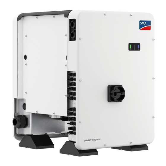
3 Product Overview SMA Solar Technology AG Product Overview Product Description Figure 1: Design of the Product Position Designation Cover AC Connection Unit DC Connection Unit LEDs The LEDs indicate the operating state of the inverter. Cable glands for data cables... -
Page 13: Symbols On The Product
SMA Solar Technology AG 3 Product Overview Position Designation Type label The type label clearly identifies the product. The type label must remain permanently attached to the product. You will find the following informa- tion on the type label: • Device type (Model) •... -
Page 14: Interfaces And Functions
SMA Speedwire The product is equipped with SMA Speedwire as standard. SMA Speedwire is a type of communication based on the Ethernet standard. SMA Speedwire is designed for a data transfer rate of 100 Mbps and enables optimum communication between Speedwire devices within systems. - Page 15 The product is equipped with a Modbus interface. The Modbus interface is deactivated by default and must be configured as needed. The Modbus interface of the supported SMA products is designed for industrial use – via SCADA systems, for example – and has the following tasks: •...
- Page 16 A description of the tested functions and instructions on the activation and setting of functions can be found in the technical information "Grid Support Utility Interactive Inverters" at www.SMA-Solar.com. PV Rapid Shutdown Equipment The inverter is listed as PV Rapid Shutdown Equipment (PVRSE) according to UL 1741.
- Page 17 SMA Smart Connected SMA Smart Connected is the free monitoring of the inverter via the SMA Sunny Portal. Thanks to SMA Smart Connected, the PV system operator and qualified person will be informed automatically and proactively about inverter events that occur.
-
Page 18: Led Signals
3 Product Overview SMA Solar Technology AG SMA Smart Connected is activated during registration in Sunny Portal. In order to use SMA Smart Connected, it is necessary that the inverter is permanently connected to Sunny Portal and the data of the PV system operator and qualified person is stored in Sunny Portal and up-to-date. -
Page 19: Operation
☐ The respective latest version of one of the following web browsers must be installed: Chrome, Edge, Firefox, Internet Explorer or Safari. ☐ The SMA Grid Guard code of the Installer must be available for the changing of grid-relevant settings after completion of the first ten feed-in hours or installation assistant (see "Application for SMA Grid Guard Code"... - Page 20 2. If your end device has not a WPS function: • Search for WLAN networks with your end device. • Select the SSID of the inverter SMA[serial number] in the list with the found WLAN networks. • Enter the inverter WLAN password. Within the first ten feed-in hours and prior to completing the configuration by means of the installation assistant, you must use the standard WLAN password SMA12345.
-
Page 21: Establishing A Connection Via Ethernet In The Local Network
☐ The respective latest version of one of the following web browsers must be installed: Chrome, Edge, Firefox, Internet Explorer or Safari. ☐ The SMA Grid Guard code of the Installer must be available for the changing of grid-relevant settings after completion of the first ten feed-in hours or installation assistant (see "Application for SMA Grid Guard Code"... -
Page 22: Establishing A Connection Via Wlan In The Local Network
☐ The respective latest version of one of the following web browsers must be installed: Chrome, Edge, Firefox, Internet Explorer or Safari. ☐ The SMA Grid Guard code of the Installer must be available for the changing of grid-relevant settings after completion of the first ten feed-in hours or installation assistant (see "Application for SMA Grid Guard Code"... -
Page 23: Logging In And Out Of The User Interface
After the IP address has been confirmed by pressing the enter key, a message might appear indicating that the connection to the user interface of the inverter is not secure. SMA Solar Technology AG guarantees that calling up the user interface is secure. • Continue loading the user interface. -
Page 24: Start Page Design Of The User Interface
4 Operation SMA Solar Technology AG Start Page Design of the User Interface Figure 2: Start page design of the user interface (example) STP33-62-US-41-BA-en_es-10 User Manual... - Page 25 User settings Provides the following functions, depending on the user group logged in: • Starting the installation assistant • SMA Grid Guard login • Logout Help Provides the following functions: • Displaying information on Open Source licenses used • Link to the website of SMA Solar Technology AG User Manual STP33-62-US-41-BA-en_es-10...
-
Page 26: Displaying And Downloading The Stored Data
4 Operation SMA Solar Technology AG Posi- Designation Description tion Status bar Displays the following information: • Inverter serial number • Inverter firmware version • IP address of the inverter within the local network and/or IP address of the inverter during WLAN connection •... -
Page 27: Activating The Smart Inverter Screen
SMA Solar Technology AG 4 Operation Procedure: 1. Activate the user interface (see Section 4.1, page 19). 2. Log into the user interface (see Section 4.2, page 23). 3. Select the menu Data. 4. Select the folder Data. 5. To call up the data, select the respective folder and click on the required file. -
Page 28: Activate Wps Function
Requirement: ☐ When configuring after completion of the first ten feed-in hours or after exiting the installation assistant, the SMA Grid Guard code must be available in order to change the grid-relevant parameters (see "Application for SMA Grid Guard Code" at www.SMA-Solar.com). Procedure: 1. -
Page 29: Switching Wlan On And Off
SMA Solar Technology AG 4 Operation Activating WPS function for automatic connection to a network Requirements: ☐ WLAN must be activated in the product. ☐ WPS must be activated on the router. Procedure: 1. Activate the user interface (see Section 4.1, page 19). -
Page 30: Switching The Dynamic Power Display Off
4 Operation SMA Solar Technology AG • To switch off the connection in the local network in the parameter group PV system communication > WLAN, select the parameter WLAN is turned on and set this to No. Switching WLAN On If you have switched the WLAN function for direct connection or for connection in the local network off, you can switch the WLAN function back on in accordance with the following procedure. -
Page 31: Changing Operating Parameters
3. Call up the menu Device Parameters. 4. Select [Edit parameters]. 5. Log in using the SMA Grid Guard code to change those parameters designated by a lock (only for installers): • Select the menu User Settings (see Section 4.3, page 24). -
Page 32: Configuring The Country Data Set
4 Operation SMA Solar Technology AG Accepting the settings Saving the made settings is indicated by an hourglass symbol on the user interface. If the DC voltage is sufficient, the data is transferred directly to the inverter and accepted. If the DC voltage is too low (e. g. -
Page 33: Configuring The Rapid Shutdown Function
SMA Solar Technology AG 4 Operation 4. In the context menu, select [Starting the installation assistant]. 5. Select [Save and next] until you reach the Feed-in management step. 6. Configure the feed-in management as desired. 4.14 Configuring the Rapid Shutdown Function The Rapid Shutdown function of the inverter must be enabled if the PV modules or PV strings are equipped with an additional DC disconnection unit that disconnects the PV array from the inverter. - Page 34 4 Operation SMA Solar Technology AG Procedure: 1. Call up the menu Device Parameters. 2. Select [Edit parameters]. 3. In the parameter group Device > Multifunction relay > Operating mode select the parameter Operating mode of multifunction relay or Mlt.OpMode and set the desired operating mode.
-
Page 35: Configuring The Modbus Function
4.17 Setting SMA OptiTrac Global Peak For partially shaded PV modules, you should set the interval at which the inverter is to optimize the MPP of the PV system. If you do not want to use SMA OptiTrac Global Peak feature, you can deactivate the feature. -
Page 36: Deactivating The Arc-Fault Circuit Interrupter (Afci)
4 Operation SMA Solar Technology AG 4.18 Deactivating the Arc-Fault Circuit Interrupter (AFCI) The basic procedure for changing operating parameters is explained in another section (see Section 4.11 "Changing Operating Parameters", page 31). Procedure: • Select the parameter AFCI switched on or AfciIsOn and set to No. -
Page 37: Updating The Firmware
4 Operation Requirements: ☐ Changes to grid-relevant parameters must be approved by the responsible grid operator. ☐ The SMA Grid Guard code must be available (see "Application for SMA Grid Guard Code" at www.SMA-Solar.com). Procedure: 1. Activate the user interface (see Section 4.1, page 19). - Page 38 The update file is, for example, available for download on the product page of the inverter at www.SMA-Solar.com. Make sure that only the update file to which the inverter is to be updated must be saved on the USB flash drive.
-
Page 39: Cleaning The Inverter
SMA Solar Technology AG 5 Cleaning the Inverter Cleaning the Inverter NOTICE Damage due to cleaning agents The use of cleaning agents may cause damage to the product and its components. • Clean the product and all its components only with a cloth moistened with clear water. -
Page 40: Troubleshooting
Installer. The password for the user group Installer is the same as the system password in Sunny Portal. Procedure: 1. Request PUK (application form available at www.SMA-Solar.com). 2. Activate the user interface (see Section 4.1, page 19). 3. Enter the PUK instead of the password into the field Password. -
Page 41: Event Messages
SMA Solar Technology AG 6 Troubleshooting Event Messages Event number Message, cause and corrective measures Grid fault The grid voltage or grid impedance at the connection point of the inverter is too high. The inverter has disconnected from the utility grid. - Page 42 6 Troubleshooting SMA Solar Technology AG Event number Message, cause and corrective measures Grid fault The power frequency is not within the permissible range. The inverter has dis- connected from the utility grid. Corrective measures: • If possible, check the power frequency and observe how often fluctuations occur.
- Page 43 SMA Solar Technology AG 6 Troubleshooting Event number Message, cause and corrective measures PE conn. missing > Check connection The grounding conductor is not correctly connected. Corrective measures: • Ensure that the grounding conductor is correctly connected. 3401 3402 DC overvoltage > Disconnect generator 3404 Overvoltage at the DC input.
- Page 44 6 Troubleshooting SMA Solar Technology AG Event number Message, cause and corrective measures 3801 3802 DC overcurrent > Check generator 3803 Overcurrent at the DC input. The inverter briefly interrupts feed-in operation. 3805 Corrective measures: 3806 • If this message is displayed frequently, ensure that the PV array has been 3807 correctly rated and wired.
- Page 45 Parameters could not be set using the memory card. The inverter continues to feed in. Corrective measures: • Ensure that the parameters are set correctly. • Ensure that the SMA Grid Guard code is available. 7106 Update file defect. The update file is defective. The update failed. The inverter continues to feed...
- Page 46 6 Troubleshooting SMA Solar Technology AG Event number Message, cause and corrective measures 7320 The device with serial number [xx] was successfully updated to firmware version [xxx]. The firmware update was completed successfully. 7330 Condition test failed The testing of the update conditions was not successful. The firmware update package is not suitable for this inverter.
- Page 47 SMA Solar Technology AG 6 Troubleshooting Event number Message, cause and corrective measures 7348 Incorrect file format The configuration file is not of the required format or is damaged. Corrective measures: • Ensure that the selected configuration file is of the required format and is not damaged.
- Page 48 6 Troubleshooting SMA Solar Technology AG Event number Message, cause and corrective measures 7619 Communication fault with meter unit > Check communication to meter The inverter is not receiving any data from the energy meter. Corrective measures: • Ensure that the energy meter is correctly integrated into the same network as the inverter (see energy meter manual).
- Page 49 9003 Grid parameter locked Changes to the grid parameters are now blocked. In order to be able to make changes to the grid parameters, from now on you must log in using the SMA Grid Guard code. 9005 Changing of grid parameters not possible > Ensure DC supply This error can have the following causes: •...
- Page 50 6 Troubleshooting SMA Solar Technology AG Event number Message, cause and corrective measures 9034 Error in Rapid Shutdown System This message can have the following causes: • The Rapid Shutdown Function was not correctly configured. • The PV generator could not be correctly disconnected. Voltage can be applied to the DC inputs of the inverter.
- Page 51 SMA Solar Technology AG 6 Troubleshooting Event number Message, cause and corrective measures 10110 Time synchronization failed: |xx| No time information could be called up from the set NTP server. Corrective measures: • Ensure that the NTP server was configured correctly.
- Page 52 6 Troubleshooting SMA Solar Technology AG Event number Message, cause and corrective measures 10251 [Interface]: communication status goes to [OK / Warning / Error / Not connected] The communication status to the network switch or DHCP server (router) has changed. An additional error message may be displayed.
- Page 53 SMA Solar Technology AG 6 Troubleshooting Event number Message, cause and corrective measures 10255 [Interface]: Network load OK The network load has returned to a normal range after being busy. 10282 [User group]-Login via [protocol] locked After several incorrect login attempts, login has been blocked for a limited time.
- Page 54 6 Troubleshooting SMA Solar Technology AG Event number Message, cause and corrective measures 10286 WLAN connection lost The inverter has lost WLAN connection to the selected network. Corrective measures: • Ensure that the WLAN router or WLAN Access Point is still active.
- Page 55 SMA Solar Technology AG 6 Troubleshooting Event number Message, cause and corrective measures 10909 Fac Min [xxx] Hz 10910 Disconn. threshold [xxx] [xx] 10911 Stand. Val. [xxx] [xx] 10912 Disconn. time [xx] s 27103 Set parameter The parameter changes are being adopted.
-
Page 56: Checking The Pv System For Ground Faults
6 Troubleshooting SMA Solar Technology AG Checking the PV System for Ground Faults DANGER Danger to life due to electric shock when touching live system components in case of a ground fault If a ground fault occurs, parts of the system may still be live. Touching live parts and cables results in death or lethal injuries due to electric shock. - Page 57 SMA Solar Technology AG 6 Troubleshooting 2. Measure the voltages: • Measure the voltage between the positive terminal and the ground potential (PE). • Measure the voltage between the negative terminal and the ground potential (PE). • Measure the voltage between the positive and negative terminals.
- Page 58 40 MOhm and for polycrystalline and monocrystalline PV modules approximately 50 MOhm per PV module (for further information on calculating the insulation resistance see the Technical Information "Insulation Resistance (Riso) of Non-Galvanically Isolated PV Systems" at www.SMA-Solar.com). Required devices: ☐ Suitable device for safe disconnection and short-circuiting ☐...
-
Page 59: Resetting The Operation Inhibition After Detection Of An Arc Fault
SMA Solar Technology AG 6 Troubleshooting 3. Install the short circuit device. 4. Connect the measuring device for insulation resistance. 5. Short-circuit the first string. 6. Set the test voltage. The test voltage should be as close as possible to the maximum system voltage of the PV modules but must not exceed it (see datasheet of the PV modules). -
Page 60: Accessories
7 Accessories SMA Solar Technology AG Accessories You will find the accessories for your product in the following overview. If required, these can be ordered from SMA Solar Technology AG or your distributor. Designation Short designation SMA order number SMA Antenna Exten-... -
Page 61: Compliance Information
Changes or modifications made to this equipment not expressly approved by SMA Solar Technology AG may void the FCC authorization to operate this equipment. -
Page 62: Contact
9 Contact SMA Solar Technology AG Contact If you have technical problems with our products, please contact the SMA Service Line. The following data is required in order to provide you with the necessary assistance: • Device type • Serial number • Firmware version •... - Page 63 Disposiciones legales Disposiciones legales SMA Solar Technology AG es propietaria de todos los derechos de la información que se facilita en esta documentación. Queda prohibida la reproducción total o parcial de este documento, así como su almacenamiento en un sistema de recuperación y toda transmisión electrónica, mecánica, fotográfica, magnética o de otra índole sin previa autorización por escrito de SMA Solar...
- Page 64 Índice SMA Solar Technology AG Índice Indicaciones sobre este documento ........66 Área de validez......................66 Grupo de destinatarios....................66 Contenido y estructura del documento..............66 Niveles de advertencia....................66 Símbolos del documento ................... 67 Marcas de texto en el documento................67 Denominación en el documento ................
- Page 65 4.15 Modificación del modo de funcionamiento del relé multifunción......97 4.16 Configuración de la función Modbus............... 98 4.17 Configuración de SMA OptiTrac Global Peak............99 4.18 Desactivación del sistema de detección e interrupción de arcos voltaicos (AFCI).......................... 100 4.19 Activación de la detección de fallos de string ............100 4.20...
-
Page 66: Indicaciones Sobre Este Documento
La versión actual de este documento y más información sobre el producto se encuentran en formato PDF y como e-Manual en www.SMA-Solar.com. También puede acceder al e-Manual a través de la interfaz de usuario del producto. -
Page 67: Símbolos Del Documento
SMA Solar Technology AG 1 Indicaciones sobre este documento ATENCIÓN Representa una advertencia que, de no ser observada, puede causar lesiones físicas leves o de gravedad media. PRECAUCIÓN Representa una advertencia que, de no ser observada, puede causar daños materiales. -
Page 68: Información Adicional
“Parámetros y valores de medición” Información técnica Vista general de todos los parámetros de funcionamiento del inver- sor y sus opciones de ajuste "Interfaz de SMA y de SunSpec Modbus®" Información técnica Información sobre la interfaz Modbus “Parámetros y valores de medición de Modbus®”... -
Page 69: Seguridad
Para realizar cualquier intervención en el producto, como modificaciones o remodelaciones, deberá contar con el permiso expreso y por escrito de SMA Solar Technology AG. Los cambios no autorizados conllevan la pérdida de los derechos de garantía, así como la extinción de la autorización de operación. -
Page 70: Indicaciones Importantes Para La Seguridad
SMA Solar Technology AG no asume responsabilidad alguna relativa al cumplimiento o al incumplimiento de la legislación o las disposiciones relacionadas con la instalación del producto. - Page 71 SMA Solar Technology AG 2 Seguridad PELIGRO Peligro de muerte por descarga eléctrica si se tocan partes de la planta bajo tensión en caso de fallo a tierra En caso de fallo a tierra los componentes de la planta pueden estar bajo tensión. El contacto con componentes conductores de tensión o cables puede causar la muerte o lesiones mortales...
- Page 72 2 Seguridad SMA Solar Technology AG PRECAUCIÓN Daños en el producto provocados por arena, polvo y humedad Si penetra arena, polvo y humedad, el producto podría resultar dañado y sus funciones podrían verse limitadas. • Abra el producto solamente si la humedad del aire se encuentra dentro de los valores límite y si el entorno está...
-
Page 73: Vista General Del Producto
SMA Solar Technology AG 3 Vista general del producto Vista general del producto Descripción del producto Imagen 1: Diseño del producto Posición Denominación Cubierta Connection Unit de CA Connection Unit de CC Leds Los leds señalizan el estado de funcionamiento del inversor. -
Page 74: Símbolos Del Producto
3 Vista general del producto SMA Solar Technology AG Posición Denominación Placa de características La placa de características identifica el producto de forma inequívoca. La placa de características debe permanecer colocada en el producto en todo momento. En la placa de características encontrará esta informa- ción:... -
Page 75: Interfaces Y Funciones
Sunny Portal a través de un registrador de datos (como SMA Data Manager) o distribuir los inversores en varias plantas en el Sunny Portal. Para acceder a su planta visualizada, puede utilizar directamente el navegador de internet de su dispositivo terminal. - Page 76 El producto está equipado con una interfaz Modbus, que viene desactivada de fábrica y que, en caso necesario, se deberá configurar. La interfaz Modbus de los productos de SMA compatibles ha sido concebida para el uso industrial de, por ejemplo, sistemas SCADA, y tiene estas funciones: •...
- Page 77 SMA Solar Technology AG 3 Vista general del producto Gestión de red El inversor ha sido comprobado según la UL 1741 SA (07/09/2016) para cumplir con los Source Requirements Documents (documentos de origen) de los estados disponibles en el momento del test. Para conectar el inversor a la red pública, no se necesitan dispositivos adicionales de monitorización de la red.
- Page 78 3 Vista general del producto SMA Solar Technology AG Por defecto, la función de Rapid Shutdown está desactivada. La función de Rapid Shutdown únicamente debe activarse si hay módulos conmutadores fotovoltaicos autorizados instalados dentro de los módulos fotovoltaicos o entre los módulos fotovoltaicos y el inversor. La función de Rapid Shutdown puede activarse seleccionando el modo de funcionamiento apropiado para los módulos conmutadores fotovoltaicos en la interfaz de usuario durante o después de la puesta en...
-
Page 79: Señales De Los Leds
SMA Smart Connected SMA Smart Connected es la monitorización gratuita del inversor a través de Sunny Portal. Mediante SMA Smart Connected el operador de la planta y el especialista reciben información de forma automática y proactiva sobre los eventos que se producen en el inversor. La activación de SMA Smart Connected se realiza durante el registro en Sunny Portal. Para utilizar SMA Smart Connected es necesario que el inversor esté... - Page 80 3 Vista general del producto SMA Solar Technology AG Señal de LED Explicación El led rojo está encendido Se ha producido un evento Cuando se produce un evento, en la interfaz de usuario del inversor o en el producto de comunicación aparece además un aviso de evento concreto y el respectivo número de evento.
-
Page 81: Manejo
Después de confirmar la dirección IP pulsando la tecla intro, puede aparecer un aviso que advierte de que la conexión con la interfaz de usuario del inversor no es segura. SMA Solar Technology AG garantiza que es seguro acceder a la interfaz de usuario. • Continúa cargando la interfaz de usuario. - Page 82 SMA Solar Technology AG SSID, dirección IP y contraseñas necesarias • SSID en la WLAN: SMA[número de serie] (por ejemplo, SMA0123456789) • Contraseña WLAN estándar (puede utilizarse hasta que finalice la configuración con la ayuda del asistente de instalación o antes de que transcurran las primeras 10 hora de inyección): SMA12345...
-
Page 83: Conexión Mediante Ethernet En La Red Local
Después de confirmar la dirección IP pulsando la tecla intro, puede aparecer un aviso que advierte de que la conexión con la interfaz de usuario del inversor no es segura. SMA Solar Technology AG garantiza que es seguro acceder a la interfaz de usuario. • Continuar cargando la interfaz de usuario. -
Page 84: Conexión Mediante Wlan En La Red Local
Después de confirmar la dirección IP pulsando la tecla intro, puede aparecer un aviso que advierte de que la conexión con la interfaz de usuario del inversor no es segura. SMA Solar Technology AG garantiza que es seguro acceder a la interfaz de usuario. • Continuar cargando la interfaz de usuario. -
Page 85: Inicio Y Cierre De Sesión En La Interfaz De Usuario
Después de confirmar la dirección IP pulsando la tecla intro, puede aparecer un aviso que advierte de que la conexión con la interfaz de usuario del inversor no es segura. SMA Solar Technology AG garantiza que es seguro acceder a la interfaz de usuario. • Continuar cargando la interfaz de usuario. - Page 86 4 Manejo SMA Solar Technology AG Primer inicio de sesión como instalador o usuario Contraseña para plantas registradas en un producto de comunicación La contraseña del grupo Instalador es también la contraseña de la planta. Si le asigna al grupo Instalador a través de la interfaz de usuario del inversor una contraseña, esta debe coincidir con la contraseña de la planta.
-
Page 87: Estructura De La Página De Inicio De La Interfaz De Usuario
SMA Solar Technology AG 4 Manejo Estructura de la página de inicio de la interfaz de usuario Imagen 2: Estructura de la página de inicio de la interfaz de usuario (ejemplo) Instrucciones de uso STP33-62-US-41-BA-en_es-10... - Page 88 • Iniciar el asistente de instalación • Inicio de sesión SMA Grid Guard • Cierre de sesión Ayuda Ofrece estas funciones: • Mostrar información sobre las licencias de código abierto utilizadas • Enlace a la página web de SMA Solar Technology AG STP33-62-US-41-BA-en_es-10 Instrucciones de uso...
- Page 89 SMA Solar Technology AG 4 Manejo Posi- Denomina- Significado ción ción Barra de es- Muestra esta información: tado • Número de serie del inversor • Versión de firmware del inversor • Dirección IP del inversor en la red local o dirección IP del inversor en caso de conexión por WLAN...
-
Page 90: Visualización Y Descarga De Datos Almacenados
4 Manejo SMA Solar Technology AG Visualización y descarga de datos almacenados Si hay insertado un medio de almacenamiento externo, puede visualizar y descargar los datos almacenados. Procedimiento: 1. Abra la interfaz de usuario (consulte el capítulo 4.1, página 81). 2. Inicie sesión en la interfaz de usuario (consulte el capítulo 4.2, página 85). -
Page 91: Activación De La Función Wps
☐ En caso de configuración después de las primeras 10 horas de inyección o después de la finalización del asistente de instalación, para modificar los parámetros relevantes para la red debe conocer el código SMA Grid Guard (consulte “Formulario de solicitud del código SMA Grid Guard” en www.SMA-Solar.com). -
Page 92: Activación Y Desactivación De Wlan
4 Manejo SMA Solar Technology AG • Conexión automática con una red (como a través del rúter) • Conexión directa entre el producto y un dispositivo terminal Según el uso para el cual desee utilizar la función WPS, debe proceder a la activación de forma diferente. -
Page 93: Desactivación De La Indicación De Potencia Dinámica
SMA Solar Technology AG 4 Manejo Desactivación de WLAN Si desea desactivar por completo la función WLAN, deberá desactivar tanto la conexión directa como la conexión dentro de la red local. Procedimiento: • Para desactivar la conexión directa, seleccione en el grupo de parámetros Comunicación de la planta >... -
Page 94: Modificación De La Contraseña
Modifique siempre los parámetros de funcionamiento tal y como se describe en este capítulo. Algunos parámetros que afectan al funcionamiento solo pueden visualizarlos y modificarlos especialistas introduciendo su código SMA Grid Guard personal. Requisitos: ☐ Los cambios en los parámetros relevantes para la red deben haber sido aprobados por el operador de red responsable. -
Page 95: Configuración Del Registro De Datos Nacionales
• En el menú contextual que aparece a continuación, seleccione [Inicio de sesión SMA Grid Guard]. • Introduzca el código SMA Grid Guard y seleccione [Iniciar sesión]. 6. Abra el grupo de parámetros en el que se encuentra el parámetro que desea ,modificar. 7. Modifique el parámetro deseado. -
Page 96: Configuración De La Gestión De La Inyección
4 Manejo SMA Solar Technology AG Procedimiento: • Seleccione en el grupo de parámetros Monitorización de la red > Monitorización de la red el parámetro Configurando norma nacional y configure el registro de datos nacionales deseado. 4.13 Configuración de la gestión de la inyección Si el operador de red lo exige, el inversor puede ofrecer servicios de gestión de red, que pueden... -
Page 97: Modificación Del Modo De Funcionamiento Del Relé Multifunción
SMA Solar Technology AG 4 Manejo Procedimiento: 1. Abra la interfaz de usuario (consulte el capítulo 4.1, página 81). 2. Inicie sesión en la interfaz como Instalador. 3. Seleccione el menú Ajustes del usuario en la parte derecha de la barra de menús (consulte el capítulo 4.3 “Estructura de la página de inicio de la interfaz de usuario”, página 87). -
Page 98: Configuración De La Función Modbus
Modbus. Una vez activada la interfaz, pueden modificarse los puertos de comunicación de ambos protocolos IP. Encontrará más información sobre la puesta en marcha y la configuración de la interfaz Modbus en la información técnica "Interfaz de SMA y de SunSpec Modbus®" en www.SMA-Solar.com. -
Page 99: Configuración De Sma Optitrac Global Peak
☑ El inversor optimiza el MPP de la planta fotovoltaica durante el intervalo de tiempo definido. • Para desactivar el SMA OptiTrac Global Peak, ajuste en el grupo de parámetros Lado de CC > Configuración CC > OptiTrac Global Peak el parámetro OptiTrac Global Peak a OFF. -
Page 100: Desactivación Del Sistema De Detección E Interrupción De Arcos Voltaicos (Afci)
4 Manejo SMA Solar Technology AG 4.18 Desactivación del sistema de detección e interrupción de arcos voltaicos (AFCI) El procedimiento básico para la modificación de los parámetros de funcionamiento se describe en otro capítulo (consulte el capítulo 4.11 “Modificación de los parámetros de funcionamiento”, página 94). -
Page 101: Actualización Del Firmware
Si no se ha configurado la actualización automática del inversor en el producto de comunicación (por ejemplo, SMA Data Manager, Cluster Controller o Sunny Portal) o a través de la interfaz de usuario del inversor, tiene la posibilidad de llevar a cabo una actualización manual del firmware. - Page 102 El archivo de actualización puede descargarse, por ejemplo, de la página web del inversor en www.SMA-Solar.com. Tenga en cuenta que en la memoria USB solo debe estar guardado el archivo de la actualización con el que se va a actualizar el inversor.
-
Page 103: Limpieza Del Inversor
SMA Solar Technology AG 5 Limpieza del inversor Limpieza del inversor PRECAUCIÓN Daños por productos de limpieza Si utiliza productos de limpieza, puede dañar el producto y componentes del producto. • Limpie el producto y todos los componentes del producto únicamente con un paño humedecido con agua limpia. -
Page 104: Localización De Errores
La contraseña del grupo de usuarios Instalador coincide con la contraseña de la planta en el Sunny Portal. Procedimiento: 1. Solicite el PUK (formulario disponible en www.SMA-Solar.com). 2. Abra la interfaz de usuario (consulte el capítulo 4.1, página 81). 3. En el campo Contraseña, introduzca el PUK recibido en vez de la contraseña. -
Page 105: Avisos De Evento
SMA Solar Technology AG 6 Localización de errores Avisos de evento Número de Aviso, causa y solución evento Error de red La tensión o la impedancia de red en el punto de conexión del inversor son demasiado altas. El inversor se ha desconectado de la red pública. - Page 106 6 Localización de errores SMA Solar Technology AG Número de Aviso, causa y solución evento Error de red El inversor se ha desconectado de la red pública. Se ha detectado una red aislada o una variación muy acusada de la frecuencia de red.
- Page 107 SMA Solar Technology AG 6 Localización de errores Número de Aviso, causa y solución evento Esperando tensión de red > Fallo total de la red > Comprobar fusible El cable de CA no está conectado correctamente o el registro de datos nacio- nales no está...
- Page 108 6 Localización de errores SMA Solar Technology AG Número de Aviso, causa y solución evento 3401 3402 Sobretensión CC > Desconectar el generador 3404 Sobretensión en la entrada de CC. El inversor puede sufrir daños irrepara- 3407 bles. 3410 Este aviso va acompañado de un parpadeo rápido de los leds.
- Page 109 SMA Solar Technology AG 6 Localización de errores Número de Aviso, causa y solución evento 6002 % a 6412 % Autodiagnóstico > Fallo del equipo El servicio técnico debe determinar la causa. Solución: • Póngase en contacto con el servicio técnico. 6502 Autodiagnóstico >...
- Page 110 Los parámetros no se han podido ajustar desde la tarjeta de memoria. El in- versor continúa inyectando. Solución: • Asegúrese de que ha ajustado correctamente los parámetros. • Asegúrese de que dispone del código SMA Grid Guard. 7106 Archivo de actualización defectuoso El archivo de actualización está defectuoso. La actualización ha fallado. El in- versor continúa inyectando.
- Page 111 SMA Solar Technology AG 6 Localización de errores Número de Aviso, causa y solución evento 7331 Transp. actualización iniciado Se copiará el fichero de actualización. 7332 Transp. actualización correcto El fichero de actualización se ha copiado correctamente en la memoria inter- na del inversor.
- Page 112 6 Localización de errores SMA Solar Technology AG Número de Aviso, causa y solución evento 7348 Formato incorrecto de fichero El fichero de configuración no tiene el formato requerido o está dañado. Solución: • Asegúrese de que el fichero de configuración seleccionado tenga el formato requerido y no esté...
- Page 113 SMA Solar Technology AG 6 Localización de errores Número de Aviso, causa y solución evento 7356 Error actualización WebUI La actualización de la interfaz de usuario del inversor ha fallado. Solución: • Intente realizar la actualización de nuevo. • Si este aviso aparece de nuevo, póngase en contacto con el servicio técnico.
- Page 114 8104 Solución: • Póngase en contacto con el servicio técnico. 9002 Código SMA Grid Guard no válido El código SMA Grid Guard introducido no es correcto. Los parámetros siguen estando protegidos y no pueden modificarse. Solución: • Introduzca el código SMA Grid Guard correcto. 9003 Parámetros de red bloqueados Los parámetros de red han quedado bloqueados y ya no pueden modificar-...
- Page 115 • La tensión de CC en la entrada de CC es insuficiente para el funcionamiento del ordenador central. Solución: • Introduzca el código SMA Grid Guard. • Asegúrese de que esté disponible al menos la tensión de arranque de CC (el led verde parpadea, emite una luz pulsante o está encendido).
- Page 116 6 Localización de errores SMA Solar Technology AG Número de Aviso, causa y solución evento 9035 Rapid Shutdown realizado correctamente La tensión en las entradas de CC y en la salida de CA del inversor se ha des- cargado correctamente.
- Page 117 SMA Solar Technology AG 6 Localización de errores Número de Aviso, causa y solución evento 10249 [Interfaz]: Red sobrecargada La red está sobrecargada. Los equipos no intercambian datos. Solución: • Reduzca el número de equipos de la red. • En caso necesario, amplíe los intervalos de consulta de datos.
- Page 118 6 Localización de errores SMA Solar Technology AG Número de Aviso, causa y solución evento 10253 [Interfaz]: La velocidad de conexión cambia a [100 MBit/10 MBit] La velocidad de transferencia de datos varía. La causa del estado [10 MBit] puede ser un conector o un cable defectuosos, o bien que los conectores de red están enchufados o desenchufados.
- Page 119 SMA Solar Technology AG 6 Localización de errores Número de Aviso, causa y solución evento 10283 Módulo WLAN defectuoso El módulo WLAN integrado en el inversor está defectuoso. Solución: • Póngase en contacto con el servicio técnico. 10284 No se puede establecer ninguna conexión WLAN En estos momentos, el inversor no está...
- Page 120 6 Localización de errores SMA Solar Technology AG Número de Aviso, causa y solución evento 10343 Fallo Webconnect: gateway estándar no configurado 10344 Fallo Webconnect: servidor DNS no configurado 10345 Error Webconnect: consulta DNS no se responde |xx| 10346 Error Webconnect: SIP-Proxy desconocido |xx|...
- Page 121 SMA Solar Technology AG 6 Localización de errores Número de Aviso, causa y solución evento 10912 Tiempo de desconexión medido para el punto de prueba en curso | xx| s 27103 Config. parámetros Se aplica la modificación de los parámetros.
-
Page 122: Comprobación De La Existencia De Un Fallo A Tierra En La Planta Fotovoltaica
6 Localización de errores SMA Solar Technology AG Comprobación de la existencia de un fallo a tierra en la planta fotovoltaica PELIGRO Peligro de muerte por descarga eléctrica si se tocan partes de la planta bajo tensión en caso de fallo a tierra En caso de fallo a tierra los componentes de la planta pueden estar bajo tensión. - Page 123 SMA Solar Technology AG 6 Localización de errores Procedimiento: PELIGRO Peligro de muerte por altas tensiones • Desconecte el inversor de la tensión (consulte las instrucciones de instalación del inversor). 2. Mida las tensiones: • Mida la tensión entre el polo positivo y el potencial de tierra (PE).
- Page 124 Encontrará más información para el cálculo de la resistencia del aislamiento en la información técnica “Resistencia de aislamiento (Riso) de instalaciones fotovoltaicas sin separación galvánica” en www.SMA-Solar.com. Equipos requeridos: ☐ Dispositivo adecuado para una desconexión y una puesta en cortocircuito seguras ☐...
-
Page 125: Restablecimiento Del Bloqueo Tras La Detección De Arcos Voltaicos
SMA Solar Technology AG 6 Localización de errores PELIGRO Peligro de muerte por altas tensiones • Desconecte el inversor de la tensión (consulte las instrucciones de instalación del inversor). 3. Instale el dispositivo de cortocircuito. 4. Conecte el equipo de medición de la resistencia del aislamiento. - Page 126 6 Localización de errores SMA Solar Technology AG 3. Ponga de nuevo en marcha el inversor (consulte las instrucciones de instalación de este). 4. Abra la interfaz de usuario (consulte el capítulo 4.1, página 81). 5. Inicie sesión en la interfaz como Instalador (consulte el capítulo 4.2, página 85).
-
Page 127: Accesorios
SMA Solar Technology AG 7 Accesorios Accesorios En la siguiente tabla encontrará los accesorios de su producto. Si necesita alguno de ellos, solicítelos a SMA Solar Technology AG o a su distribuidor. Denominación Descripción breve Número de pedido de SMA Antenna Exten-... -
Page 128: Información De Cumplimiento
Changes or modifications made to this equipment not expressly approved by SMA Solar Technology AG may void the FCC authorization to operate this equipment. -
Page 129: Contacto
9 Contacto Contacto Si surge algún problema técnico con nuestros productos, póngase en contacto con el Servicio Técnico de SMA. Para ayudarle de forma eficaz, necesitamos que nos facilite estos datos: • Modelo • Número de serie • Versión de firmware •... - Page 130 www.SMA-Solar.com...
Need help?
Do you have a question about the SUNNY TRIPOWER CORE1-US Series and is the answer not in the manual?
Questions and answers