SMA Sunny Tripower CORE1 Operating Manual
Hide thumbs
Also See for Sunny Tripower CORE1:
- Replacement manual (252 pages) ,
- Quick reference manual (150 pages) ,
- Operating manual (107 pages)

Subscribe to Our Youtube Channel
Related Manuals for SMA Sunny Tripower CORE1


Summary of Contents for SMA Sunny Tripower CORE1
- Page 1 Operating manual Sunny Tripower CORE1 (STP 50-40) W E R R I P O N Y T S U N ENGLISH STP50-40-BE-en-15 | Version 1.5...
- Page 2 SMA Solar Technology AG Legal Provisions The information contained in these documents is the property of SMA Solar Technology AG. No part of this document may be reproduced, stored in a retrieval system, or transmitted, in any form or by any means, be it electronic, mechanical, photographic, magnetic or otherwise, without the prior written permission of SMA Solar Technology AG.
-
Page 3: Table Of Contents
SMA Solar Technology AG Table of Contents Table of Contents Information on this Document..........Validity ........................Target Group......................Content and Structure of this Document ..............Levels of Warning Messages ..................Symbols in the Document ..................Typographies in the Document.................. Designation in the document .................. - Page 4 Configuring the Modbus Function................73 8.18 Activating the Receipt of Control Signals (Only for Italy)........74 8.19 Setting SMA OptiTrac Global Peak ................. 75 8.20 Setting the Rated Residual Current of the Residual-Current Device ......75 8.21 Activating String-Failure Detection ................75 8.22...
- Page 5 SMA Solar Technology AG Table of Contents 8.24 Updating the Firmware ....................77 Disconnecting the Inverter from Voltage Sources ....79 10 Cleaning the Inverter ............... 81 11 Troubleshooting................ 82 11.1 Forgotten Password....................82 11.2 Event Messages ......................83 11.3 Checking the PV System for Ground Faults..............
-
Page 6: Information On This Document
You will find the latest version of this document and further information on the product in PDF format and as eManual at www.SMA-Solar.com. You can also call up the eManual via the user interface of the product. Illustrations in this document are reduced to the essential information and may deviate from the real product. -
Page 7: Symbols In The Document
SMA Solar Technology AG 1 Information on this Document NOTICE Indicates a situation which, if not avoided, can result in property damage. Symbols in the Document Symbol Explanation Information that is important for a specific topic or goal, but is not safety-rele-... -
Page 8: Additional Information
"Application for SMA Grid Guard Code" Form "PUBLIC CYBER SECURITY - Guidelines for a Secure PV System Technical information Communication" "SMA GRID GUARD 10.0 - Grid management services through Technical Information SMA Inverter" "SUNNY TRIPOWER CORE1 - Simplified Implementation of Grid Technical Information and PV System Protection in PV Systems in accordance with VDE AR-... -
Page 9: Safety
All components must remain within their permitted operating ranges and their installation requirements at all times. The product must only be used in countries for which it is approved or released by SMA Solar Technology AG and the grid operator. - Page 10 2 Safety SMA Solar Technology AG DANGER Danger to life due to electric shock when live components or DC cables are touched When exposed to light, the PV modules generate high DC voltage which is present in the DC cables. Touching live DC cables results in death or lethal injuries due to electric shock.
- Page 11 SMA Solar Technology AG 2 Safety DANGER Danger to life due to electric shock in case of overvoltages and if surge protection is missing Overvoltages (e. g. in the event of a flash of lightning) can be further conducted into the building and to other connected devices in the same network via the network cables or other data cables if there is no surge protection.
- Page 12 2 Safety SMA Solar Technology AG WARNING Danger to life due to electric shock from destruction of the measuring device due to overvoltage Overvoltage can damage a measuring device and result in voltage being present in the enclosure of the measuring device. Touching the live enclosure of the measuring device results in death or lethal injuries due to electric shock.
- Page 13 Sunny Portal or the use of FTP push. High costs for the Internet connection can be the result. • SMA Solar Technology AG recommends using an Internet flat rate. Change to the names and units of grid parameters to comply with the grid-...
-
Page 14: Scope Of Delivery
3 Scope of Delivery SMA Solar Technology AG Scope of Delivery Check the scope of delivery for completeness and any externally visible damage. Contact your distributor if the scope of delivery is incomplete or damaged. Figure 1: Components included in the scope of delivery... -
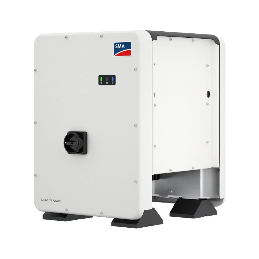
Page 15: Product Overview
SMA Solar Technology AG 4 Product Overview Product Overview Product Description Figure 2: Design of the product Position Designation Cover AC Connection Unit DC Connection Unit LEDs The LEDs indicate the operating state of the product. Display (optional) The product is equipped with a display upon request. The display shows the current operating data and events or errors. -
Page 16: Symbols On The Product
4 Product Overview SMA Solar Technology AG Position Designation Type label The type label clearly identifies the product. The type label must remain permanently attached to the product. You will find the following informa- tion on the type label: • Device type (Model) •... - Page 17 SMA Solar Technology AG 4 Product Overview Symbol Explanation Inverter Together with the green LED, this symbol indicates the operating state of the in- verter. Data transmission Together with the blue LED, this symbol indicates the status of the network con- nection.
-
Page 18: Interfaces And Functions
SMA Speedwire The product is equipped with SMA Speedwire as standard. SMA Speedwire is a type of communication based on the Ethernet standard. SMA Speedwire is designed for a data transfer rate of 100 Mbps and enables optimum communication between Speedwire devices within systems. - Page 19 The product is equipped with a Modbus interface. The Modbus interface is deactivated by default and must be configured as needed. The Modbus interface of the supported SMA products is designed for industrial use – via SCADA systems, for example – and has the following tasks: •...
- Page 20 > 3.01.00.R and an SMA I/O Module. The inverter can be connected to the monitoring unit of the grid and PV system protection device via the SMA I/O Module and receive the signal for grid disconnection (for further information see technical information "SUNNY TRIPOWER CORE1 - Simplified Implementation of Grid and PV System...
-
Page 21: Led Signals
4 Product Overview SMA Smart Connected SMA Smart Connected is the free monitoring of the inverter via the SMA Sunny Portal. Thanks to SMA Smart Connected, the PV system operator and qualified person will be informed automatically and proactively about inverter events that occur. -
Page 22: Display Messages
4 Product Overview SMA Solar Technology AG LED signal Explanation The blue LED flashes quickly WPS active for approx. two minutes The WPS function is active. (0.25 s on and 0.25 s off). The blue LED is glowing Communication active There is an active connection with a local network or there is a di- rect connection with an end device via Ethernet (e.g. -
Page 23: System Overview
SMA Solar Technology AG 4 Product Overview Display message Explanation Error An event has occurred. Instantaneous output power E-Total Total produced energy Pmax Currently set active power limit cos φ Displacement power factor cos φ Update file(s) found New firmware version available... -
Page 24: Circuitry Overview
4 Product Overview SMA Solar Technology AG 4.6.1 Circuitry Overview UTILITY GRID MEDIUM VOLTAGE TRANSFORMER DISTRIBUTION BOARD POWER SUPPLY UNIT SMA DATA CLCON-PWRSUPPLY MANAGER M ENERGY METER GRID CONNECTION POINT with energy meter 6 ... 16 A of the grid operator Typ B/C/D/K max. -
Page 25: Communication Overview
SMA Solar Technology AG 4 Product Overview 4.6.2 Communication Overview SUNNY PORTAL powered by DIRECT ennexOS GRID OPERATOR MARKETER Public Internet Ethernet LAN Ripple control signal Digital signal INTERNET SMA DATA RIPPLE CONTROL MANAGER M RECEIVER ROUTER SUNNY TRIPOWER CORE1... -
Page 26: Mounting
5 Mounting SMA Solar Technology AG Mounting Requirements for Mounting Requirements for the Mounting Location: WARNING Danger to life due to fire or explosion Despite careful construction, electrical devices can cause fires. This can result in death or serious injury. - Page 27 SMA Solar Technology AG 5 Mounting Dimensions for mounting: 79.4 79.4 M8x14/17+1 M8x14/17+1 46.2 46.2 Figure 6: Position of the anchoring points(Dimensions in mm) Operating manual STP50-40-BE-en-15...
- Page 28 ☐ When mounting with profile rails, an attachment or fixation by loading is required. When mounting with profile rails, SMA Solar Technology AG recommends to bolt the profile rails e.g. to the profile of the module frame or to attach a sheet metal (which can be weighted with stones or with sandbags) at the profile rails.
-
Page 29: Mounting The Inverter
SMA Solar Technology AG 5 Mounting 1 0 0 0 ( 3 9 . 3 ( 3 9 . 3 ( 3 9 . 3 1 0 0 0 1 0 0 0 1 0 0 0 1 0 0 0 ( 3 5 . - Page 30 5 Mounting SMA Solar Technology AG Procedure: 1. Attach each foot with two M8x40 hexagon head screws and two washers on the two external taps (M8x14) on the underside of the inverter (torque: 16 Nm). Press the packaging on the bottom side down or cut it open.
- Page 31 SMA Solar Technology AG 5 Mounting 7. Remove all four transport handles from the threaded holes. If necessary, insert a screwdriver into the holes on the transport handle and use the screwdriver to remove the transport handle. Operating manual STP50-40-BE-en-15...
-
Page 32: Electrical Connection
6 Electrical Connection SMA Solar Technology AG Electrical Connection Overview of the Connection Area Figure 9: Connection areas of the inverters' AC Connection Unit and DC Connection Unit Position Designation Slots for AC surge protection devices Terminal blocks for AC connection... -
Page 33: Ac Connection
SMA Solar Technology AG 6 Electrical Connection AC Connection 6.2.1 Requirements for the AC Connection AC cable requirements as follows: ☐ Conductor type: aluminum and copper wire ☐ External diameter: 35 mm to 48 mm ☐ Conductor cross-section of grounding conductor: 25 mm² to 120 mm²... -
Page 34: Connecting The Inverter To The Utility Grid
300 mA or higher (information about the selection of a residual-current device see technical information "Criteria for Selecting a Residual-Current Device" at www.SMA- Solar.com). Each inverter in the system must be connected to the utility grid via a separate residual-current device. - Page 35 SMA Solar Technology AG 6 Electrical Connection 5. Insert the cable gland M63 into the opening and tighten it with the counter nut from the inside. 6. Thread the AC cable through the cable gland into the AC Connection Unit. If necessary, slightly loosen the swivel nut of the cable gland.
-
Page 36: Connecting The Network Cables
6 Electrical Connection SMA Solar Technology AG 13. When N is present and connected to the corresponding terminal, remove the bridge installed as standard between N and the enclosure ( ). To do so, unscrew the screw of the terminal N and the... - Page 37 SMA Solar Technology AG 6 Electrical Connection Network cable requirements: The cable length and quality affect the quality of the signal. Observe the following cable requirements. ☐ Cable type: 100BaseTx ☐ Cable category: minimum CAT5e ☐ Plug type: RJ45 of Cat5, Cat5e or higher ☐...
-
Page 38: Connecting The Multifunction Relay
6 Electrical Connection SMA Solar Technology AG 10. Put the RJ45 plug of the cable into one of the network sockets of the communication assembly. 11. Ensure that the RJ45 plug is securely in place by pulling slightly on the cable. -
Page 39: Connection Options
SMA Solar Technology AG 6 Electrical Connection Operating mode of multi- Description function relay (Mlt.Op- Mode) Control via communica- The multifunction relay switches loads on or off according to com- tion (ComCtl) mands transmitted by a communication product. Battery bank (BatCha) The multifunction relay controls the charging of the batteries depend- ing on the power production of the PV system. - Page 40 6 Electrical Connection SMA Solar Technology AG Using the Multifunction Relay as a Fault Indicator Contact You can use the multifunction relay as a fault indicator contact and have an error or smooth operation of the inverter displayed or signaled via a suitable display device. You can connect multiple inverters to one fault indicator or operation indicator, as needed.
- Page 41 SMA Solar Technology AG 6 Electrical Connection Controlling loads via the multifunction relay or charging batteries depending on the power production of the PV system The multifunction relay can control loads or charge batteries power-dependently. To enable this function, you must connect a contactor (K1) to the multifunction relay. The contactor (K1) switches the operating current for the load on or off.
-
Page 42: Connection To The Multifunction Relay
6 Electrical Connection SMA Solar Technology AG Reporting the switching status of the grid relay The multifunction relay can trip a signal to the grid operator as soon as the inverter connects to the utility grid. To enable this function, the multifunction relays of all inverters must be connected in parallel. - Page 43 SMA Solar Technology AG 6 Electrical Connection Procedure: DANGER Danger to life due to high voltages • Disconnect the inverter from all voltage sources (see Section 9, page 79). 2. If the enclosure lid of the DC-Connection Unit is closed, remove it as follows: Unscrew all ten screws with a Torx screwdriver (TX25) and remove the enclosure lid carefully forward.
-
Page 44: Dc Connection
6 Electrical Connection SMA Solar Technology AG DC Connection 6.5.1 Requirements for the DC Connection Requirements for the PV modules per input: ☐ All PV modules should be of the same type. ☐ All PV modules should be aligned and tilted identically. - Page 45 SMA Solar Technology AG 6 Electrical Connection NOTICE Destruction of the inverter due to overvoltage If the open-circuit voltage of the PV modules exceeds the maximum input voltage of the inverter, the inverter can be destroyed due to overvoltage. • If the open-circuit voltage of the PV modules exceeds the maximum input voltage of the inverter, do not connect any strings to the inverter and check the design of the PV system.
-
Page 46: Connecting The Pv Array
6 Electrical Connection SMA Solar Technology AG ☑ The stranded wire can be seen inside the clamping bracket chamber. 4. If the stranded wire is not visible in the chamber, the cable is not correctly inserted and the connector must be reassembled. To do this, the cable must be removed from the connector. - Page 47 SMA Solar Technology AG 6 Electrical Connection NOTICE Damage to the inverter due to ground fault on DC side during operation Due to the transformerless topology of the product, the occurance of ground faults on DC side during operation can lead to irreparable damage. Damages to the product due to a faulty or damaged DC installation are not covered by warranty.
- Page 48 6 Electrical Connection SMA Solar Technology AG 3. Secure the DC load-break switch against reconnection using a padlock. 4. Measure the PV array voltage. Ensure that the maximum input voltage of the inverter is adhered to and that there is no ground fault in the PV array.
-
Page 49: Disassembling The Dc Connectors
SMA Solar Technology AG 6 Electrical Connection 12. Insert the DC connectors with sealing plugs into the corresponding DC inputs on the inverter. ☑ The DC connectors snap into place. 13. Ensure that the DC connectors with sealing plugs are securely in place. - Page 50 6 Electrical Connection SMA Solar Technology AG 3. Unlock the DC connector. To do this, insert a flat- blade screwdriver (blade width: 3.5 mm) into the side catch mechanism and pry the catch mechanism open. 4. Carefully pull the DC connector apart.
-
Page 51: Commissioning
Commissioning Procedure Commissioning a product in SMA Energy Systems If the product is used in an SMA Energy System, the commissioning must be performed according to the manual of the SMA Energy System. The procedure and the sequence may differ from the steps described in this section. -
Page 52: Commissioning The Inverter
7 Commissioning SMA Solar Technology AG Procedure For PV systems in Italy or Dubai: Start the self-test. Section 7.4, page 55 Make further inverter settings as needed. Section 8, page 56 Commissioning the Inverter Requirements: ☐ The AC circuit breaker must be correctly rated and mounted. -
Page 53: Selecting A Configuration Option
On the Configuring the Inverter page, different configuration options are available to choose from. Select one of the options and proceed for the selected option as described below. SMA Solar Technology AG recommends carrying out the configuration with the installation assistant. This way, you ensure that all relevant parameters are set for optimal inverter operation. - Page 54 7 Commissioning SMA Solar Technology AG • Adoption of configuration from a file • Configuration with the installation assistant (recommended) • Manual configuration Accepting the settings Saving the made settings is indicated by an hourglass symbol on the user interface. If the DC voltage is sufficient, the data is transferred directly to the inverter and accepted.
-
Page 55: Starting The Self-Test (For Italy And Dubai)
SMA Solar Technology AG 7 Commissioning Procedure: 1. Select the configuration option Manual Configuration. ☑ The Device Parameters menu on the user interface will open and all available parameter groups of the inverter will be displayed. 2. Select [Edit parameters]. -
Page 56: Operation
☐ The respective latest version of one of the following web browsers must be installed: Chrome, Edge, Firefox, Internet Explorer or Safari. ☐ The SMA Grid Guard code of the Installer must be available for the changing of grid-relevant settings after completion of the first ten feed-in hours or installation assistant (see "Application for SMA Grid Guard Code"... -
Page 57: Establishing A Direct Connection Via Wlan
☐ JavaScript must be enabled in the web browser of the end device. ☐ The SMA Grid Guard code of the Installer must be available for the changing of grid-relevant settings after completion of the first ten feed-in hours or installation assistant (see "Application for SMA Grid Guard Code"... -
Page 58: Establishing A Connection Via Ethernet In The Local Network
Connection with WLAN network search 1. Search for WLAN networks with your end device. 2. Select the SSID of the inverter SMA[serial number] in the list with the found WLAN networks. 3. Enter the device-specific WLAN password (see WPA2-PSK on the type label of the product or the rear side of the manual included in delivery). -
Page 59: Establishing A Connection Via Wlan In The Local Network
☐ The respective latest version of one of the following web browsers must be installed: Chrome, Edge, Firefox, Internet Explorer or Safari. ☐ The SMA Grid Guard code of the Installer must be available for the changing of grid-relevant settings after completion of the first ten feed-in hours or installation assistant (see "Application for SMA Grid Guard Code"... -
Page 60: Logging In And Out Of The User Interface
☐ The respective latest version of one of the following web browsers must be installed: Chrome, Edge, Firefox, Internet Explorer or Safari. ☐ The SMA Grid Guard code of the Installer must be available for the changing of grid-relevant settings after completion of the first ten feed-in hours or installation assistant (see "Application for SMA Grid Guard Code"... - Page 61 4. Click on Save. 5. In the New password field, enter a password for the Installer user group. Assign a uniform password to all SMA devices to be registered in a system. The installer password is also the system password.
-
Page 62: Start Page Design Of The User Interface
8 Operation SMA Solar Technology AG Start Page Design of the User Interface Figure 16: Design of the user interface's start page (example) STP50-40-BE-en-15 Operating manual... -
Page 63: Device Configuration
• Starting the installation assistant • SMA Grid Guard login • Logout Help Provides the following functions: • Displaying information on Open Source licenses used • Link to the website of SMA Solar Technology AG Operating manual STP50-40-BE-en-15... - Page 64 8 Operation SMA Solar Technology AG Position Designation Description Status bar Displays the following information: • Inverter serial number • Inverter firmware version • IP address of the inverter within the local network and/or IP address of the inverter during WLAN connection •...
-
Page 65: Displaying And Downloading The Stored Data
SMA Solar Technology AG 8 Operation Displaying and Downloading the Stored Data If an external storage device is plugged in, you can display and download the stored data. Procedure: 1. Activate the user interface (see Section 8.2, page 56). 2. Log into the user interface (see Section 8.3, page 60). -
Page 66: Starting The Installation Assistant
Requirement: ☐ When configuring after completion of the first ten feed-in hours or after exiting the installation assistant, the SMA Grid Guard code must be available in order to change the grid-relevant parameters (see "Application for SMA Grid Guard Code" at www.SMA-Solar.com). Procedure: 1. -
Page 67: Activate Wps Function
SMA Solar Technology AG 8 Operation Activate WPS Function The WPS function can be used for different purposes: • Automatic connection to a network (e.g. via router) • Direct connection between the product and an end device Depending on the intended application of the WPS function, the procedure for activation will vary. -
Page 68: Switching The Dynamic Power Display Off
8 Operation SMA Solar Technology AG Switching WLAN Off If you would like to switch the WLAN function off completely, you must switch off both the direct connection and the connection in the local network. Procedure: • To switch off the direct connection in the parameter group PV system communication >... -
Page 69: Changing The Password
3. Call up the menu Device Parameters. 4. Click on [Edit parameters]. 5. Log in using the SMA Grid Guard code to change those parameters designated by a lock (only for installers): • Select the menu User Settings (see Section 8.4, page 62). -
Page 70: Configuring The Country Data Set
8 Operation SMA Solar Technology AG • Enter the SMA Grid Guard code and select [Login]. 6. Expand the parameter group that contains the parameter which is to be configured. 7. Change the desired parameters. 8. Select [Save all] to save the changes. -
Page 71: Configuring The Active Power Mode
SMA Solar Technology AG 8 Operation 8.14 Configuring the Active Power Mode Starting the installation assistant 1. Open the user interface (see Section 8.2, page 56). 2. Log in as Installer. 3. Start the installation assistant (see Section 8.7, page 66). 4. Select [Save and continue] after each step up until the step Grid management service. -
Page 72: Changing The Operating Mode Of The Multifunction Relay
8 Operation SMA Solar Technology AG This means that if the "Q on Demand 24/7" function" is active, no other grid-supporting functions (e.g., cos phi) are possible between day and night operation of the inverter. Should an independent reactive power provision be desired between day- and night operation, the reactive power provision must be communicated to the inverter via a superordinate control unit. -
Page 73: Configuring The Modbus Function
The Modbus interface is deactivated by default and the communication ports 502 set. ® ® ® In order to access SMA invertes with SMA Modbus or SunSpec Modbus , the Modbus interface must be activated. After activating the interface, the communication ports of both IP protocols can be changed. -
Page 74: Activating The Receipt Of Control Signals (Only For Italy)
Procedure: • Activate the Modbus interface and adjust the communication ports if necessary (see the technical information "SMA and SunSpec Modbus® Interface" at www.SMA-Solar.com). 8.18 Activating the Receipt of Control Signals (Only for Italy) In order for PV systems in Italy to receive control commands from the grid operator, set the following parameters. -
Page 75: Setting Sma Optitrac Global Peak
8.19 Setting SMA OptiTrac Global Peak For partially shaded PV modules, you should set the interval at which the inverter is to optimize the MPP of the PV system. If you do not want to use SMA OptiTrac Global Peak feature, you can deactivate the feature. -
Page 76: Saving The Configuration In A File
Requirements: ☐ Changes to grid-relevant parameters must be approved by the responsible grid operator. ☐ The SMA Grid Guard code must be available (see "Application for SMA Grid Guard Code" at www.SMA-Solar.com). Procedure: 1. Open the user interface (see Section 8.2, page 56). -
Page 77: Updating The Firmware
The update file is, for example, available for download on the product page of the inverter at www.SMA-Solar.com. Ensure that only the update file to which the inverter is to be updated must be stored on the USB flash drive. - Page 78 8 Operation SMA Solar Technology AG 4. Insert the USB flash drive in the USB port on the communication assembly. 5. Commission the inverter (see Section 7.2, page 52). ☑ During start-up phase of the inverter, the desired firmware is being installed.
-
Page 79: Disconnecting The Inverter From Voltage Sources
SMA Solar Technology AG 9 Disconnecting the Inverter from Voltage Sources Disconnecting the Inverter from Voltage Sources Prior to performing any work on the inverter, always disconnect it from all voltage sources as described in this section. Always adhere to the prescribed sequence. - Page 80 9 Disconnecting the Inverter from Voltage Sources SMA Solar Technology AG 8. Release and remove the DC connectors. To do so, insert a flat-blade screwdriver or an angled screwdriver (blade width: 3.5 mm) into one of the side slots and pull the DC connectors out. When...
-
Page 81: Cleaning The Inverter
SMA Solar Technology AG 10 Cleaning the Inverter 10 Cleaning the Inverter NOTICE Damage due to cleaning agents The use of cleaning agents may cause damage to the product and its components. • Clean the product and all its components only with a cloth moistened with clear water. -
Page 82: Troubleshooting
Installer is the same as the system password in the communication product. Procedure: 1. Request PUK (application form available at www.SMA-Solar.com). 2. Open the user interface (see Section 8.2, page 56). 3. Enter the PUK instead of the password into the field Password. -
Page 83: Event Messages
SMA Solar Technology AG 11 Troubleshooting 11.2 Event Messages Event number Message, cause and corrective measures Grid fault The grid voltage or grid impedance at the connection point of the inverter is too high. The inverter has disconnected from the utility grid. - Page 84 11 Troubleshooting SMA Solar Technology AG Event number Message, cause and corrective measures Grid fault The power frequency is not within the permissible range. The inverter has dis- connected from the utility grid. Corrective measures: • If possible, check the power frequency and observe how often fluctuations occur.
- Page 85 SMA Solar Technology AG 11 Troubleshooting Event number Message, cause and corrective measures PE conn. missing > Check connection The grounding conductor is not correctly connected. Corrective measures: • Ensure that the grounding conductor is correctly connected. 3401 3402 DC overvoltage > Disconnect generator 3404 Overvoltage at the DC input.
- Page 86 11 Troubleshooting SMA Solar Technology AG Event number Message, cause and corrective measures 3801 3802 DC overcurrent > Check generator 3803 Overcurrent at the DC input. The inverter briefly interrupts feed-in operation. 3805 Corrective measures: 3806 • If this message is displayed frequently, ensure that the PV array has been 3807 correctly rated and wired.
- Page 87 Parameters could not be set using the memory card. The inverter continues to feed in. Corrective measures: • Ensure that the parameters are set correctly. • Ensure that the SMA Grid Guard code is available. 7106 Update file defect. The update file is defective. The update failed. The inverter continues to feed...
- Page 88 11 Troubleshooting SMA Solar Technology AG Event number Message, cause and corrective measures 7331 Update transport started Update file is being copied. 7332 Update transport successful Update file was copied successfully to the inverter's internal memory. 7333 Update transport failed Update file could not be copied to the inverter's internal memory.
- Page 89 SMA Solar Technology AG 11 Troubleshooting Event number Message, cause and corrective measures 7350 Transfer of a configuration file has started The configuration file is being transferred. 7351 Update WLAN The inverter is updating the WLAN module. 7352 Update of WLAN not successful The update of the WLAN module failed.
- Page 90 Message, cause and corrective measures 7622 No communication with the I/O module? This event is displayed during a device-internal communication error with the SMA I/O Module. For safety reasons, the inverter disconnects from the utility grid. 7702 Interference device The cause must be determined by the Service.
- Page 91 9003 Grid parameter locked Changes to the grid parameters are now blocked. In order to be able to make changes to the grid parameters, from now on you must log in using the SMA Grid Guard code. 9005 Changing of grid parameters not possible > Ensure DC supply This error can have the following causes: •...
- Page 92 11 Troubleshooting SMA Solar Technology AG Event number Message, cause and corrective measures 9034 Error in Rapid Shutdown System This message can have the following causes: • The Rapid Shutdown Function was not correctly configured. • The PV generator could not be correctly disconnected. Voltage can be applied to the DC inputs of the inverter.
- Page 93 SMA Solar Technology AG 11 Troubleshooting Event number Message, cause and corrective measures 10110 Time synchronization failed: |xx| No time information could be called up from the set NTP server. Corrective measures: • Ensure that the NTP server was configured correctly.
- Page 94 11 Troubleshooting SMA Solar Technology AG Event number Message, cause and corrective measures 10251 [Interface]: communication status goes to [OK / Warning / Error / Not connected] The communication status to the network switch or DHCP server (router) has changed. An additional error message may be displayed.
- Page 95 SMA Solar Technology AG 11 Troubleshooting Event number Message, cause and corrective measures 10255 [Interface]: Network load OK The network load has returned to a normal range after being busy. 10282 [User group]-Login via [protocol] locked After several incorrect login attempts, login has been blocked for a limited time.
- Page 96 11 Troubleshooting SMA Solar Technology AG Event number Message, cause and corrective measures 10286 WLAN connection lost The inverter has lost WLAN connection to the selected network. Corrective measures: • Ensure that the WLAN router or WLAN Access Point is still active.
-
Page 97: Checking The Pv System For Ground Faults
SMA Solar Technology AG 11 Troubleshooting Event number Message, cause and corrective measures 27107 Update file OK The update file found is valid. 27301 Update communication The inverter is updating the communication component. 27302 Update main CPU The inverter is updating the inverter component. - Page 98 11 Troubleshooting SMA Solar Technology AG WARNING Danger to life due to electric shock from destruction of the measuring device due to overvoltage Overvoltage can damage a measuring device and result in voltage being present in the enclosure of the measuring device. Touching the live enclosure of the measuring device results in death or lethal injuries due to electric shock.
- Page 99 SMA Solar Technology AG 11 Troubleshooting Location of the ground fault The example shows a ground fault between the second and third PV module. V = 200 V V = 300 V 100 V 100 V 100 V 100 V...
- Page 100 40 MOhm and for polycrystalline and monocrystalline PV modules approximately 50 MOhm per PV module (for further information on calculating the insulation resistance see the Technical Information "Insulation Resistance (Riso) of Non-Galvanically Isolated PV Systems" at www.SMA-Solar.com). Required devices: ☐ Suitable device for safe disconnection and short-circuiting ☐...
- Page 101 SMA Solar Technology AG 11 Troubleshooting 12. Recommission the inverter. 13. If the inverter still displays an insulation error, contact the Service (see Section 15, page 111). The PV modules might not be suitable for the inverter in the present quantity. Operating manual...
-
Page 102: Decommissioning The Inverter
12 Decommissioning the Inverter SMA Solar Technology AG 12 Decommissioning the Inverter To decommission the inverter completely upon completion of its service life, proceed as described in this Section. CAUTION Risk of injury when lifting the inverter, or if it is dropped The inverter weighs 84 kg. - Page 103 SMA Solar Technology AG 12 Decommissioning the Inverter 5. Remove the AC cable from the inverter. 6. Remove the M63 cable gland from the enclosure opening in the AC connection unit. To do so, remove the inside counter nut and remove the cable gland from the enclosure opening.
- Page 104 12 Decommissioning the Inverter SMA Solar Technology AG 13. When the DC surge arresters are inserted, pull the surge arresters out of the slots. To do so, squeeze the grooved areas on the left and right sides of the surge arrester.
- Page 105 SMA Solar Technology AG 12 Decommissioning the Inverter • Remove all four transport handles from the threaded holes. If necessary, insert a screwdriver into the holes on the transport handle and use the screwdriver to remove the transport handle. • Pull the upper part of the original packaging over the inverter.
-
Page 106: Technical Data
13 Technical Data SMA Solar Technology AG 13 Technical Data DC Input Maximum PV array power 75000 Wp STC Maximum input voltage 1000 V MPP voltage range 500 V to 800 V Rated input voltage 670 V Minimum input voltage 150 V Initial input voltage 188 V... -
Page 107: Protective Devices
SMA Solar Technology AG 13 Technical Data Operating range at AC power frequency 50 Hz 44 Hz to 55 Hz Operating range at AC power frequency 60 Hz 54 Hz to 65 Hz Power factor at rated power Displacement power factor, adjustable 0.0 overexcited to 0.0 underexcited Feed-in phases Phase connection... -
Page 108: General Data
13 Technical Data SMA Solar Technology AG General Data Width x height x depth, without feet or DC load- 592 mm x 733 mm x 679 mm break switch Weight 84 kg Length x width x height of the packaging 800 mm x 600 mm x 886 mm Transport weight 100 kg Climatic category in accordance with IEC... -
Page 109: Data Storage Capacity
SMA Solar Technology AG 13 Technical Data Threshold for relative humidity, non-condensing 100 % Extended air pressure range 79.5 kPa to 106 kPa Transport in accordance with IEC 60721-3-4, Class 2K3 Temperature range -40°C to +70°C Equipment DC connection SUNCLIX DC connector AC terminal Screw terminals... -
Page 110: Accessories
14 Accessories SMA Solar Technology AG 14 Accessories You will find the accessories for your product in the following overview. If required, these can be ordered from SMA Solar Technology AG or your distributor. Designation Short designation SMA order number... -
Page 111: Contact
SMA Solar Technology AG 15 Contact 15 Contact If you have technical problems with our products, please contact the SMA Service Line. The following data is required in order to provide you with the necessary assistance: • Device type • Serial number •... - Page 112 SMA Solar (Thailand) Co., Ltd. 대한민국 SMA Technology Korea Co., Ltd. กรุ ง เทพฯ 서울 +66 2 670 6999 +82-2-520-2666 South Africa SMA Solar Technology South Argentina SMA South America SPA Africa Pty Ltd. Brasil Santiago de Chile Cape Town Chile +562 2820 2101 08600SUNNY (08600 78669) Perú...
-
Page 113: Eu Declaration Of Conformity
(L 174/88, June 8, 2011) and 2015/863/EU (L 137/10, March 31, 2015) (RoHS) SMA Solar Technology AG confirms herewith that the products described in this document are in compliance with the fundamental requirements and other relevant provisions of the above- mentioned directives. The entire EU Declaration of Conformity can be found at www.SMA- Solar.com. - Page 114 www.SMA-Solar.com...
Need help?
Do you have a question about the Sunny Tripower CORE1 and is the answer not in the manual?
Questions and answers