Sign In
Upload
Manuals
Brands
FANOX Manuals
Relays
SIA-C
FANOX SIA-C Manuals
Manuals and User Guides for FANOX SIA-C. We have
2
FANOX SIA-C manuals available for free PDF download: User Manual
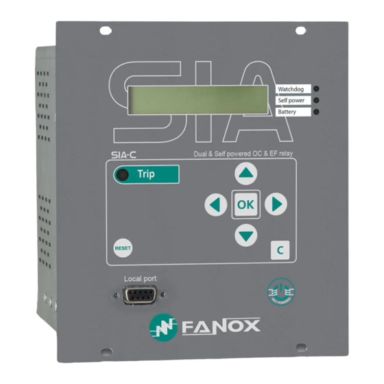
FANOX SIA-C User Manual (217 pages)
Self & Dual Powered Overcurrent & Earth Fault Protection Relay
Brand:
FANOX
| Category:
Relays
| Size: 7 MB
Table of Contents
Table of Contents
2
1 Reception, Handling, Installation
6
Unpacking
6
Reception of Relays
6
Handling Electronic Device
6
Installation, Commissioning and Service
7
Storage
7
Recycling
7
2 Dimensions and Connection Diagrams
8
Case Dimensions MM of SIA-C with Mechanics Type B and C
8
Case Dimensions MM of SIA-C with Mechanics Type D
10
Case Dimensions MM of SIA-C with Mechanics Type E and G
11
Case Dimensions MM of SIA-C with Mechanics Type F (Withdrawable)
12
KITCOM Dimensions (in MM)
13
Striker Dimensions (in MM)
14
Prt
15
TCM Dimensions (in MM)
16
Connection Diagrams
17
Separated Terminals Connectors for Measurement and Power Supply
17
Simple Terminals Connector (Measurement and Power Supply)
31
Terminals
37
Physical Layout of SIA-C Type D Terminals
37
Physical Layout of SIA-C Types B and C Terminals
41
Physical Layout of SIA-C Type E Terminals
45
Physical Layout of SIA-C Type F Terminals (Withdrawable Model)
49
Physical Layout of SIA-C Type G Terminals
50
3 Description
51
Introduction
51
Functional Diagram
56
Selection & Ordering Codes
57
Phase CT and Neutral CT Selection
58
Load Curve for Relay SIA-C/1
59
Load Curve for Relay SIA-C/5
59
4 Protection Functions
60
General Settings
60
Function 50. Phase Instantaneous Overcurrent
60
Function 51. Phase Inverse Time Overcurrent
61
Function 50G. Neutral Instantaneous Overcurrent
62
Function 51G. Neutral Inverse Time Overcurrent
62
Function 46. Negative Sequence Inverse Time Overcurrent
63
Function 46BC. Broken Conductor Detection
64
Function 49. Thermal Image Overload
64
Thermal Image Measurement Evolution Graphic
65
Function 52. Circuit Breaker Monitoring
68
Circuit Breaker Opening and Closing Commands
72
Openings Number Counter
72
Accumulated Amperes: I2T Counter
72
Configured Number of Openings in a Time Frame Exceeded Alarm
72
Function 50BF. Breaker Failure Monitoring
73
Function 79. Recloser
74
Counter to Record the Number of Reclosings
77
Function CLP. Cold Load Pickup
77
Function 74CT. Current Transformers Supervision
78
Function SHB. Second Harmonic Blocking
79
Function. External Trip
79
Function 68. Zone Selection Interlocking (ZSI)
80
Function 74TCS. Trip Voltage Supervision
83
Settings Groups
83
IEC60255-151 Curves
84
IEEE Curves
90
Application Examples
94
5 Monitoring and Control
99
Measurements
99
Load Data Profiling (LDP)
100
Counters
100
States and Events
100
Disturbance Fault Recording
109
Self-Diagnosis
111
Digital Inputs
112
Digital Outputs
113
Programmable Logic Control
113
Commands
122
Test Program
123
Power Supply
125
Self Powering
125
Battery Power: 12V, with a KITCOM Adaptor
125
Vac, 50/60 Hz Auxiliary Power
128
VDC or 48 VDC Auxiliary Power Supply
128
Internal Commisioning Battery
128
Switch on to Fault (SOTF) Characteristic
131
SIA-C for Striker
132
SIA-C Withdrawable Model
134
SIA-C for Coil
136
Opening Mechanism
138
Striker Activation
139
Coil Activation by Means of a Free Potential Contact
140
Coil Activation by Means of TCM Adapter
140
6 Technical Specifications and Standards
141
Technical Specifications
141
Thermal Resistance
146
Standards
147
7 Communication and Hmi
149
Communication
149
Front Communication. RS232
149
Rear Communication. RS485
150
Bistable Magnetic Indicators
151
LED Indicators
152
LCD and Keypad
154
Sicom Communications Program
155
How to Install SICOM Software
155
Setting-Up the Session: Password and Access Levels
156
Menus
157
Standby Mode Screen
157
Accessing the Menus
157
Date-Time Menu
157
Versions
158
Communication Parameters
158
Contrast
158
Test Menu
159
Functions Menu
165
Measurements Menu
167
Status Menu
169
Settings Menu
188
Events Menu
199
Counters Menu
201
Commands Menu
202
Demand Menu
203
Fault Reports
204
PGC and Output Configuration Menu
205
8 Commissioning
209
Checklist for Commissioning
209
Inspection
209
Electrostatic Discharge
209
Visual Inspection
209
Earthing
209
Current Transformers
209
Auxiliary Power
209
RS232 Front Communications Port
210
Commissioning
210
9 Appendix
211
Identification
211
Checks
212
Test Menu
212
Register of Commissioning Settings
212
Inputs
214
Outputs
214
Leds
214
Comments
215
Advertisement
FANOX SIA-C User Manual (189 pages)
Dual & Self powered overcurrent & earth fault relay
Brand:
FANOX
| Category:
Relays
| Size: 6 MB
Table of Contents
Reception, Handling, Installation
6
Installation, Commissioning and Service
7
Dimensions and Connection Diagrams
8
Case Dimensions MM of SIA-C with Mechanics Type B and C
10
Case Dimensions MM of SIA-C with Mechanics Type D
12
Case Dimensions MM of SIA-C with Mechanics Type E and G
13
Case Dimensions MM of SIA-C with Mechanics Type F (Withdrawable)
14
KITCOM Dimensions
15
Striker Dimensions (in MM)
16
TCM Dimensions
17
Connection Diagrams
18
Simple Terminals Connector (Measurement and Power Supply)
32
Terminals
38
Physical Layout of SIA-C Types B and C Terminals
42
Physical Layout of SIA-C Type E Terminals
46
Physical Layout of SIA-C Type F Terminals (Withdrawable Model)
50
Physical Layout of SIA-C Type G Terminals
51
Description
52
Functional Diagram
57
Selection & Ordering Data
58
Phase CT and Neutral CT Selection
59
Load Curve for Relay SIA-C/1
60
Protection Functions
61
P Function. Phase Inverse Time Overcurrent
62
N/G Function. Neutral Inverse Time Overcurrent
63
External Trip
65
Protection Settings
70
Settings Table
72
IEC60255-151 Curves
73
ANSI-IEEE Curves
78
Application Examples
82
Monitoring and Control
88
Status and Events
89
Fault Reports
97
Self-Diagnosis
98
Digital Inputs
99
Programmable Logic Control & Digital Outputs
100
Function. Trip Output Lockout
103
Power Supply
105
Vac or 110 Vac, 50/60 Hz Auxiliary Power
107
VDC or 48 VDC Auxiliary Power Supply
108
SIA-C for Striker
109
SIA-C Withdrawable Model
111
SIA-C for Coil
113
Opening Mechanism
115
Striker Activation
116
Coil Activation by Means of a Free Potential Contact
117
Technical Specifications and Standards
118
Thermal Resistance
121
Communication and Hmi
125
Bistable Magnetic Indicators
127
LED Indicators
128
LCD and Keypad
131
How to Install SICOM Software
132
Setting-Up the Session: Password and Access Levels
133
Menus
134
Date-Time Menu
135
Contrast
136
Test Menu
137
Functions Menu
143
Measurements Menu
145
Status Menu
146
Settings Menu
157
Events Menu
163
Demand Menu
165
Fault Reports
166
PLC and Output Configuration Menu
167
Modbus Rtu Protocol
171
Modbus Package Format
172
Exemptions an Error Answers
173
Memory Map of SIA-C
174
Counters Map
178
Examples of Modbus Frames
179
Commissioning
180
RS232 Front Communications Port
181
Appendix
182
Checks
183
Inputs
185
Comments
186
Advertisement
Related Products
Fanox SIA C Series
Fanox SIAC116B1011AB
Fanox SIAB000B0010AA
Fanox SIA-B Series
FANOX SIA-F Series
FANOX SIA-B Standard Series
FANOX SIAB110FC032AC
FANOX SIA F
FANOX SIA-F
FANOX SIA B
FANOX Categories
Relays
Multimeter
Controller
Timer
Measuring Instruments
More FANOX Manuals
Login
Sign In
OR
Sign in with Facebook
Sign in with Google
Upload manual
Upload from disk
Upload from URL