
Subscribe to Our Youtube Channel
Related Manuals for FANOX SIA-B Standard CTs


Summary of Contents for FANOX SIA-B Standard CTs
- Page 1 SIA-B Standard CTs Self & Dual Power Overcurrent Protection Relay INSTALLATION & COMMISSIONING GUIDE www.fanox.com Installation_Guide_SIAB110FC232AC_Rev. 01 1 / 36...
-
Page 2: Table Of Contents
Direct Access ........................ 20 7.3. Menus ..........................21 ..COMMISSIONING ......................29 8.1. Thermal resistance ....................... 29 8.2. Self powering ........................ 31 8.3. Measurements ......................31 8.4. Protection functions ....................31 ..SIAB110FC232AC REGISTRY ..................35 www.fanox.com Installation_Guide_SIAB110FC232AC_Rev. 01 2 / 36... -
Page 3: Reception & Installation
Testing protocol is a certificate that relay has passed all factory testing process with correct results. In case some fault is detected, consider putting into quarantine period the relay and contact Fanox for further instructions. 1.2. Relay verification When relay is unpacked, please, take your... -
Page 4: Powering The Relay Up
Once “C” key is pressed the name of phase and neutral currents (instead the complete model) is displayed on the top of LCD Standby screen. • Serial number (8 digits) and Firmware Version → HOLD ▲ www.fanox.com Installation_Guide_SIAB110FC232AC_Rev. 01 4 / 36... - Page 5 Then press OK key to start the test menu. Action Checking Output 1 Output 1 activated ▼ Output 2 Output 2 activated ▼ Output 3 Output 3 activated ▼ TripOutput Trip Output activated Skip from test menu www.fanox.com Installation_Guide_SIAB110FC232AC_Rev. 01 5 / 36...
-
Page 6: Relay Intallation
Remove the battery and replace it respecting polarity (+ facing up): Battery characteristics: • AA 3.6V lithium battery • Model LS14500 from SAFT • Do not use rechargeable batteries or other types of battery www.fanox.com Installation_Guide_SIAB110FC232AC_Rev. 01 6 / 36... -
Page 7: Relay Rear Part
Digital output 1 NC Phase C current input for measurement and self-power Digital output 1 NO Phase C current output for measurement and self-power Digital 2 common output Neutral current input for measurement Digital output 2 NC www.fanox.com Installation_Guide_SIAB110FC232AC_Rev. 01 7 / 36... -
Page 8: Connection Diagram
Auxiliary power supply - Digital output 3 NC Common of the Inputs Digital output 3 NO Input 1 RS485 Remote communication B18-B19 Input 2 Input 3 1.6. Connection diagram 2. USER INTERFACE 2.1. Relay front part www.fanox.com Installation_Guide_SIAB110FC232AC_Rev. 01 8 / 36... -
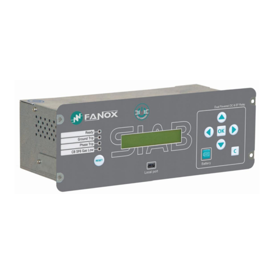
Page 9: Led Indicators
CB SF6 Gas Low 2.3. How to install SICOM software To install the SICom it is necessary the following link: http://fanox.blob.core.windows.net/sicom/publish.htm The link will open the next screen, where key “install” must be pressed: The necessary drivers depending on the operative system can be downloaded from this page. -
Page 10: Functional Diagram
(passwords with more or less characters will not be accepted). By default, the equipment is programmed with the following passwords and their associated levels: PASSWORD ACCESS LEVEL 2222 3333 4444 5555 3. FUNCTIONAL DIAGRAM www.fanox.com Installation_Guide_SIAB110FC232AC_Rev. 01 10 / 36... -
Page 11: Technical Specifications
Time Delay: 0.02 to 300.00 s (step 0.01 s) Time Dial (TMS): 0.01 to 1.5 (step 0.01) Curve, activation level 110% Curve, deactivation level 100% Defined time, activation level 100% Defined time, deactivation level 95% www.fanox.com Installation_Guide_SIAB110FC232AC_Rev. 01 11 / 36... - Page 12 Maximum number of openings: 1 to 10,000 (step 1) Function Maximum accumulated amperes: 0 to 100,000 (M(A²)) (step 1) Opening time: 0.02 to 30 s (step 0.01 s) Closing time: 0.02 to 30 s (step 0.01 s) www.fanox.com Installation_Guide_SIAB110FC232AC_Rev. 01 12 / 36...
-
Page 13: Phase Ct And Neutral Ct Selection
SIA-B relay requires current transformers with the following specifications: SIAB/1: CT Burden 2 VA The relay is able to measure up to 30xIn, specifically, the range of measurement is from 0.1 till 30 times the nominal current. www.fanox.com Installation_Guide_SIAB110FC232AC_Rev. 01 13 / 36... -
Page 14: Iec60255-151 Curves
The IEEE curves follow the following mathematical equation: − adjusted And we have the following curves: • Inverse Curve • Very Inverse Curve • Extremely Inverse Curve www.fanox.com Installation_Guide_SIAB110FC232AC_Rev. 01 14 / 36... -
Page 15: Opening Mechanism
On the other hand, if a higher level that the required by the striker is selected, the activation of the striker is guaranteed, however, the fault trip time during start-up may be increased. Fanox encourages selecting the correct value of this critical setting and offers its expertise at any doubt. -
Page 16: Programable Logic Control
NOTE: As it is described above, the options NOR_LATCH, NAND_PULSES and NAND_LATCH are not available in the relay. Although, using SICOM software allows the user to configure these options, the relay will not recognize them and it will not work properly. www.fanox.com Installation_Guide_SIAB110FC232AC_Rev. 01 16 / 36... - Page 17 To get the outputs all together to be operative at the same time, it is required Single phase→305 mA or Three phases→170 mA. To activate an output it is required Single phase→270 mA or Three phases→90 mA. Once the relay detects these levels of current these outputs are instantaneously operative. www.fanox.com Installation_Guide_SIAB110FC232AC_Rev. 01 17 / 36...
-
Page 18: Leds
AND4 • General Trip LEDS • Phase Trip LED 3 AND4 • General Trip • LED 4 Input 2 Leds require, to be activated, the following mínimum current: • Single-phase→270 mA • Three-phase→90 mA www.fanox.com Installation_Guide_SIAB110FC232AC_Rev. 01 18 / 36... -
Page 19: Flowchart
Once “Output 1” appears, pressing “OK” the Output is activated and pressing “OK” again, it is deactivated. To go through all options, press “▼”. To activate and deactivate the options follow the same steps as in case of Output 1. www.fanox.com Installation_Guide_SIAB110FC232AC_Rev. 01 19 / 36... -
Page 20: Direct Access
Press the “C” key to return to the standby mode screen. Communication parameters Hold “▼” key from standby menu to access to communication parameters menu. Press the “C” key to return to the standby mode screen. www.fanox.com Installation_Guide_SIAB110FC232AC_Rev. 01 20 / 36... -
Page 21: Menus
“MEASUREMENTS” and press “▼” key to overview the rest of the menus in the relay To return to standby screen, press “C” key. It is also possible to access to Fault reports by pressing “◄” key. www.fanox.com Installation_Guide_SIAB110FC232AC_Rev. 01 21 / 36... - Page 22 “OK” when the desired option appears. Use “►” key to assign that state to a LED. After insering the password, It will be possible to assign the selected state to the configuration. www.fanox.com Installation_Guide_SIAB110FC232AC_Rev. 01 22 / 36...
- Page 23 “OK” key to access the settings that belong to this group. Use the “▲” and “▼” keys to move through the different settings. The information that appears underneath the setting name is its value. www.fanox.com Installation_Guide_SIAB110FC232AC_Rev. 01 23 / 36...
- Page 24 Use “▼” key to choose the wanted option (permission, curve type, time dial, tap or time delay) and press “OK” to access to its settings parameters. After inserting the password 5555 it will be possible to adjust the wanted value. www.fanox.com Installation_Guide_SIAB110FC232AC_Rev. 01 24 / 36...
- Page 25 GENERAL settings. Use “▼” key to overview the options and press “OK” when “CT Phase Ratio” option appears. After inserting the password 5555 it will be possible to adjust the wanted value. www.fanox.com Installation_Guide_SIAB110FC232AC_Rev. 01 25 / 36...
- Page 26 After the erasing of the events it will be appear there is 1 event corresponding to “Events erased” NOTE: When the events are deleted, the fault reports persist in the relay to analyze the fault situation until these faults reports are deleted consciously by the user. www.fanox.com Installation_Guide_SIAB110FC232AC_Rev. 01 26 / 36...
- Page 27 “COMMANDS” screen. Press "OK" and use the “▲” and “▼” keys to position the cursor over the commands. Pressing “OK” it is possible to execute the command after nserting the password. www.fanox.com Installation_Guide_SIAB110FC232AC_Rev. 01 27 / 36...
- Page 28 “▲” and “▼” keys to position the cursor over the faults. How to delete the Load data profiling To delete the demand from the relay it is necessary to insert the password 5555 from the demand menu. www.fanox.com Installation_Guide_SIAB110FC232AC_Rev. 01 28 / 36...
-
Page 29: Commissioning
RELAY WITHSTAND GENERATION MODE SYSTEM CONNECTION ENERGY WAVEFORM Single phase Phase- NOT APPLY P-N: Neutral Phase- P-P: = 2x Phase Three phase Phase- Balanced (120°) P-N Balanced: Neutral Unbalanced (0°) P-N Unbalanced: = 3x www.fanox.com Installation_Guide_SIAB110FC232AC_Rev. 01 29 / 36... - Page 30 By following these recommendations, relay should pass commissioning test successfully. If commissioning test is performed not following these recommendations, manufacturer won’t be responsible for relay failure. www.fanox.com Installation_Guide_SIAB110FC232AC_Rev. 01 30 / 36...
-
Page 31: Self Powering
Adjust the Sverker current generator with HOLD 0.2A, and suddenly, inject it to the relay, as it would happened in real situation when circuit breaker is close, powering network line. From this value, increase the current to achieve the function pick-up and the function trip. www.fanox.com Installation_Guide_SIAB110FC232AC_Rev. 01 31 / 36... - Page 32 Permission: YES. Curve: IEC Inverse. Dial: 0.05 TAP: 0.5xIn. Theoretical tripping time= 3.67 seconds (Fault current 0.55 A) The following information will be checked: Pick-up at 110% of the tap Trip output is activated www.fanox.com Installation_Guide_SIAB110FC232AC_Rev. 01 32 / 36...
- Page 33 Led 1 is activated Led 3 is activated • 51G Inverse time neutral overcurrent protection: TEST 1 Settings: Permission: YES. Curve: IEC Inverse. Dial: 0.05 TAP: 0.3xIn. Theoretical tripping time= 3.67 seconds (Fault current 0.33 A) www.fanox.com Installation_Guide_SIAB110FC232AC_Rev. 01 33 / 36...
- Page 34 Take into account this time is calculated through an equation and this time depends on the injected current, so doing a ramp is possible but the theoretical tripping time will not be checked. www.fanox.com Installation_Guide_SIAB110FC232AC_Rev. 01 34 / 36...
-
Page 35: Siab110Fc232Ac Registry
OK 50G-1: OK 51 phase A: 51 phase B: 51 phase C: OK OK OK 51G: Protection Functions OK OK OK SHB: OK OK www.fanox.com Installation_Guide_SIAB110FC232AC_Rev. 01 35 / 36... - Page 36 Bizkaia Science and Technology Park Building, 604 Derio, 48160 Bizkaia SPAIN T. +34 94 471 14 09 fanox@fanox.com www.fanox.com www.fanox.com Installation_Guide_SIAB110FC232AC_Rev. 01 36 / 36...
Need help?
Do you have a question about the SIA-B Standard CTs and is the answer not in the manual?
Questions and answers