
Subscribe to Our Youtube Channel
Related Manuals for FANOX SIA D


Summary of Contents for FANOX SIA D
- Page 1 ISO 9001:2008 SIA D Overcurrent relay USER MANUAL 1 / 117 SIA-D_ www.fanox.com Rev. 07...
- Page 2 Accumulated amps counter: I2t ....................26 4.7.4. Excessive openings in a time window ..................26 4.8. 67N1 67N2 F ........26 UNCTION EUTRAL DIRECTIONAL OVERCURRENT PROTECTION 4.9............................28 RIPPING 2 / 117 SIA-D_ www.fanox.com Rev. 07...
- Page 3 7.7.8. Functions Menu ........................67 7.7.9. Measurements Menu ........................ 68 7.7.10. Status Menu ..........................68 7.7.11. Settings Menu ........................... 70 7.7.12. Events Menu ..........................72 3 / 117 SIA-D_ www.fanox.com Rev. 07...
- Page 4 .............................. 111 HECKS 10.3............................111 EST MENU 10.4....................111 EGISTER OF COMMISSIONING SETTINGS 10.4.1. CT Ratio: ........................... 111 10.4.2. 50P: ............................111 4 / 117 SIA-D_ www.fanox.com Rev. 07...
- Page 5 10.4.10. Tripping Bus ..........................113 10.5.......................... 113 NPUT CONFIGURATION 10.6........................114 UTPUT CONFIGURATION 10.7............................115 OMMENTS 10.8. NOTES: ............................. 116 5 / 117 SIA-D_ www.fanox.com Rev. 07...
-
Page 6: Handling Electronic Equipment
It is necessary to inspect the equipment at the time it is delivered to ensure that the relays have not been damaged during transport. If any defect is found, the transport company and FANOX should be informed immediately. If the relays are not for immediate use, they should be returned to their original packaging. - Page 7 All electrical power sources should be removed before performing this operation to avoid the risk of electrical discharge. This product must be disposed of in a safe way. It should not be incinerated or brought into contact with water sources like rivers, lakes, etc… 7 / 117 SIA-D_ www.fanox.com Rev. 07...
- Page 8 ISO 9001:2008 2. DIMENSIONS AND CONNECTION DIAGRAMS 2.1. Case Dimensions mm 8 / 117 SIA-D_ www.fanox.com Rev. 07...
- Page 9 ISO 9001:2008 2.2. KITCOM Dimensions 2.3. Connection Diagrams 2.3.1. 3 Phase CT and neutral CT Connection (Revision A) 9 / 117 SIA-D_ www.fanox.com Rev. 07...
- Page 10 ISO 9001:2008 2.3.2. 3 Phase CT and residual neutral Connection (Revision A) 2.3.3. 3 Phase CT and neutral CT Connection (Revision B) 10 / 117 SIA-D_ www.fanox.com Rev. 07...
- Page 11 2.4.1. Terminals of Revision A models A-phase current input for metering Input common A-phase current output for metering Input 1 B-phase current input for metering Input 2 B-phase current output for metering Input 3 11 / 117 SIA-D_ www.fanox.com Rev. 07...
- Page 12 A-phase current input for metering Input common A-phase current output for metering Input 1 B-phase current input for metering Input 2 B-phase current output for metering Input 3 C-phase current input for metering Input 4 12 / 117 SIA-D_ www.fanox.com Rev. 07...
-
Page 13: Equipment Description
Worldwide, the energy sector is currently undergoing a profound change as a result of high levels of energy demand; more distribution lines and advanced supervision systems are required. Given the need for creating intelligent infrastructure, FANOX has developed the SIA family of products to carry out this function. - Page 14 (RS485). The RS232 port allows a PC to be connected, which can be used to monitor the equipment using the SICom communications program (supplied by FANOX). A 12V battery can also be used to power the equipment through this front port by using the adapter (KITCOM). The rear port RS485 allows the equipment to be integrated as part of a system (SCADA).
- Page 15 Up to 3 Tripping Bus (2 inputs and 2 outputs) (3*) Power supply Auxiliary voltage 110-230 Vac / 90-300 Vdc Auxiliary voltage: 24-48 Vdc Optional Battery power: 12V with an RS232 adapter (2) 15 / 117 SIA-D_ www.fanox.com Rev. 07...
- Page 16 (3*) Available only in Revision B models. 3.3. Functions Diagram 3.4. Phase CT and neutral CT selection The following table shows a summary of phase and neutral CT combinations: Model Phase Neutral Phase range Neutral range 16 / 117 SIA-D_ www.fanox.com Rev. 07...
- Page 17 CT’s and relay must be taken into account. PRECISSION BURDEN RELAYS 5P10 0,5 VA SIA‐D/1 5P20 0,5 VA SIA‐D/1 5P30 0,5 VA SIA‐D/1 5P10 1 VA SIA‐D/5 5P20 1 VA SIA‐D/5 5P30 1 VA SIA‐D/5 LOAD CURVE FOR RELAY SIA-D/1 17 / 117 SIA-D_ www.fanox.com Rev. 07...
- Page 18 50P + 51P + 50N + 51N + 52 0,1 A 0,2 A 50 Hz + Breaker 50 Hz + Circuit Breaker 60 Hz + Breaker 60 Hz + Circuit Breaker 110-230 Vac 90-300 Vdc 24-48 Vdc 18 / 117 SIA-D_ www.fanox.com Rev. 07...
- Page 19 4O + 4I With volatile RAM memory With non-volatile RAM memory With non-volatile RAM (events + osc) English, Spanish, French English, Spanish, French, Turkish English, Spanish, French, Polish First Revision Second Revision Third Revision 19 / 117 SIA-D_ www.fanox.com Rev. 07...
- Page 20 Output 4 of revision A was normally open and All the models with Tripping bus in revision B provides the contact normally and one bit for power supply open and the contact normally closed. monitoring. 20 / 117 SIA-D_ www.fanox.com Rev. 07...
-
Page 21: Power Supply
The function activates at 100% of the preset input, and deactivates at 95%. The reset is instantaneous. The accuracy of the operating time is equal to the preset time plus a maximum of 30 ms. 21 / 117 SIA-D_ www.fanox.com Rev. 07... - Page 22 The function activates at 100% of the preset input, and deactivates at 95%. The reset is instantaneous. The accuracy of the operation time is equal to the preset time plus a maximum of 30 ms. 22 / 117 SIA-D_ www.fanox.com Rev. 07...
- Page 23 Group Description Minimum Maximum Step Unit Default Breaker blocking Blocking Yes/No Blocking limit 7,00 20,00 0,01 I nominal 7,00 23 / 117 SIA-D_ www.fanox.com Rev. 07...
- Page 24 No. of configured accumulated (l2t) amps exceeded exceeds "Maximum accumulated amps" setting Activated if the number of openings exceeds the setting in "Excessive repeated openings" for the Repeated Trips time set in "Time of excessive repeated openings" 24 / 117 SIA-D_ www.fanox.com Rev. 07...
- Page 25 For the commands to have an effect, they should be assigned to the corresponding outputs. The "Open circuit breaker" and "Close circuit breaker" bits are assigned to their corresponding outputs in the "CONTROL" status group in the status menu. 25 / 117 SIA-D_ www.fanox.com Rev. 07...
- Page 26 If the directional option is not activated, the 67N function behaves like a 50N function. The actuation time is started when the following conditions are met simultaneously: 26 / 117 SIA-D_ www.fanox.com Rev. 07...
- Page 27 The accuracy of the operation time is equal to the preset time plus a maximum of 30 ms. The operation area of the directional adjusted to an operation angle of 90º and a semi-cone angle of 60º is graphically shown below. 27 / 117 SIA-D_ www.fanox.com Rev. 07...
- Page 28 ISO 9001:2008 angulo semicono = 60º angulo operación = 90º angulo semicono = 60º 4.9. Tripping Bus Since revision B, all models include the possibility of tripping bus: 28 / 117 SIA-D_ www.fanox.com Rev. 07...
- Page 29 If the associated permission is not enabled in the supply equipment, the activation of the corresponding input does not block the trip of this function. 29 / 117 SIA-D_ www.fanox.com Rev. 07...
- Page 30 The objective is not keeping blocked the functions during an undefined time when the supply equipment inputs remain activated. In this case the typical value of adjustement of these times is the feeder tripping time plus two times the feeder opening failure time. 30 / 117 SIA-D_ www.fanox.com Rev. 07...
- Page 31 67N2 block Activation /Deactivation 50P block signalling Activation /Deactivation 51P block signalling Activation /Deactivation 50N block signalling Activation /Deactivation 51N block signalling Activation /Deactivation 67N1 block signalling Activation /Deactivation 67N2 block signalling Activation /Deactivation 31 / 117 SIA-D_ www.fanox.com Rev. 07...
-
Page 32: Equipment Settings
Extremely Curve (1*) inverse Dial 0,05 1,25 0,01 1,25 0,10 7,00 0,01 I nominal 0,50 Operating 0,02 300,0 0,01 0,02 time Breaker blocking Blocking Yes/No Blocking limit 7,00 20,00 0,01 I nominal 7,00 32 / 117 SIA-D_ www.fanox.com Rev. 07... - Page 33 Half-cone º angle Neutral directional overcurrent 67N2 Permission Yes/No 0,10 30,00 0,01 I nominal 5,00 Operating 0,02 300,0 0,01 0,02 time Directionality Yes/No Residual 4,00 110,00 voltage Operating º angle Half-cone º angle 33 / 117 SIA-D_ www.fanox.com Rev. 07...
- Page 34 0,01 time Neutral blocking 300,0 0,01 time Phase signalling 300,0 0,01 time Neutral 300,0 0,01 signalling time General Equipment's “www.fanox.com” identifier (1*) TI phase relation 2000 TI neutral 2000 relation Frequency 60/50 50 (2*) Language ENGLISH TT neutral 2000 relation (1*) The equipment identifier setting can only be set through communications.
- Page 35 The curve can be displaced on the axis using the time dial, D, which can be adjusted by the user. V is Times Tap is the initial operating current, set by the user. adjusted 35 / 117 SIA-D_ www.fanox.com Rev. 07...
- Page 36 ISO 9001:2008 36 / 117 SIA-D_ www.fanox.com Rev. 07...
- Page 37 ISO 9001:2008 37 / 117 SIA-D_ www.fanox.com Rev. 07...
- Page 38 ISO 9001:2008 38 / 117 SIA-D_ www.fanox.com Rev. 07...
-
Page 39: Monitoring And Control
"delete events" command. Events have the following structure: Unique event identifier: e.g.: 51_1.4 = 51P START Identify ON(Activated) /OFF(Deactivated): an event is generated for activations and deactivations Value Year Month Time Minutes Seconds 39 / 117 SIA-D_ www.fanox.com Rev. 07... - Page 40 51N Pick-up Activation/Deactivation Neutral current 51N Trip Activation/Deactivation Neutral current Instantaneous neutral overcurrent 50N Pick-up Activation/Deactivation Neutral current 50N Trip Activation/Deactivation Neutral current Directional Neutral Overcurrent 67N1 I0 Activaction 67N_1 67N1 V0 Activation 40 / 117 SIA-D_ www.fanox.com Rev. 07...
- Page 41 52 Closed Activation/Deactivation 52 Closing time Activation 52 Closing error Activation/Deactivation Number of openings alarm Activation l2t alarm Activation Contact 52a Contact 52b Tripping bus 50P blocking Activation/Deactivation 51P blocking Activation/Deactivation 50N blocking Activation/Deactivation 41 / 117 SIA-D_ www.fanox.com Rev. 07...
- Page 42 The maximum phase current between the Trip Activation/Deactivation activation and the deactivation of the trip in the event deactivation. External trip Activation/Deactivation Trip blocking Activation/Deactivation 48 Vdc power supply alarm Activation/Deactivation Measurement error Activation/Deactivation 42 / 117 SIA-D_ www.fanox.com Rev. 07...
- Page 43 To show this situation, the "Events error" bit is activated. This bit is reset by deleting the events (from the HMI or by using communications). 43 / 117 SIA-D_ www.fanox.com Rev. 07...
-
Page 44: Real Time Clock (Rtc)
The following information is included in each oscillographic register: Number Analog channels Phase A current Phase B current Phase C current Neutral current Neutral voltage 44 / 117 SIA-D_ www.fanox.com Rev. 07... - Page 45 67N2 Trip Phase A trip blocking activation Phase B trip blocking activation Phase C trip blocking activation Input 52a Input 52b 50P function blocking 51P function blocking External trip activation Oscillograph start Input 1 45 / 117 SIA-D_ www.fanox.com Rev. 07...
- Page 46 The following additional information is included in the COMTRADE header file (*.hdr): date-time of the oscillograph, oscillograph number, relay identification and a list of all the events that occurred in the equipment while the oscillograph was being generated. 46 / 117 SIA-D_ www.fanox.com Rev. 07...
- Page 47 Mascara 2 = 4096 Mascara 3 = Mascara 4 = Mascara 3 = 0 **************************************************************** Eventos de Oscilo: **************************************************************** Indicador Valor Medida1 Medida2 Fecha Hora Inicio 2008/10/15 11:29:11:90 Oscilo Inicio 2008/10/15 11:29:11:400 Oscilo ************************************************************ 47 / 117 SIA-D_ www.fanox.com Rev. 07...
- Page 48 Phase B block MMI Activity 50 Hz Factory settings Phase C block Command select Trip block Eeprom error Phase block Open breaker Measure error Eeprom changed Close breaker Ready Event error Protection error Settings change 48 / 117 SIA-D_ www.fanox.com Rev. 07...
-
Page 49: Configurable Inputs
3 is assigned to the 50P function blocking and to the oscillograph start and input 4 is assigned to the 50N function blocking. The external trip input is not associated with any physical input. 49 / 117 SIA-D_ www.fanox.com Rev. 07... -
Page 50: Configurable Outputs
• There is a WatchDog device both between and in main CPUs. If any CPU goes out of operation the equipment will be reset and this condition will be identified as an event. 50 / 117 SIA-D_ www.fanox.com Rev. 07... - Page 51 The RS232 communications port is installed on the front of the equipment. The connector that is used is a DB-9 female – DCE. The protocol that is used is Modbus RTU (19200 -8bit – no parity – 1 51 / 117 SIA-D_ www.fanox.com Rev. 07...
- Page 52 Fibre optics can be used in very aggressive environments, and they are connected by using the corresponding converters. Connection diagram for a RS485 bus: SIA-E SIA-E SIA-E RS232 RS485/RS232 52 / 117 SIA-D_ www.fanox.com Rev. 07...
-
Page 53: Modbus Rtu Protocol
The following key sequence is used to gain access to the test menu: from the main menu, press the keys “◄”, “▼”, and “►” in sequence and then press and hold the "OK" key until the "Test menu" 53 / 117 SIA-D_ www.fanox.com Rev. 07... - Page 54 “OK”). Press the “C” key to exit the test menu. To obtain more detailed information, the method for navigating the menus is explained graphically in the keypad and display section. 54 / 117 SIA-D_ www.fanox.com Rev. 07...
-
Page 55: Technical Specifications And Standards
Operating range: 0,10 to 7 x In (step 0,01) Curves: IEC 255-4/BS-142 Operating time: inverse curve, very inverse curve, estremely inverse curve. Defined time: 0,02 to 300 s (step 0,01 s) Dial: 0,05 to 1,25 55 / 117 SIA-D_ www.fanox.com Rev. 07... - Page 56 Time of excessive repeated openings: 1 a 300 min Application: not activated, feeder, supply and feeder-supply Bus de disparo 50P block permission: yes/no 51P block permission: yes/no 50N block permission: yes/no 51N block permission: yes/no 56 / 117 SIA-D_ www.fanox.com Rev. 07...
- Page 57 Environment Storage temperature: -20 to 70 ºC Humidity: 95% Power supply and measurement CT /5 or /1 Transformers Metallic box Mechanical features Panel Mounting 1/2 Rack – 4 U Depth: 74,6 mm IP-52 57 / 117 SIA-D_ www.fanox.com Rev. 07...
- Page 58 ISO 9001:2008 58 / 117 SIA-D_ www.fanox.com Rev. 07...
- Page 59 Level 4, Class 5 ±2 kV Line- ±2 kV Line-Line. Line. Coupling:2Ω/18μ IEC 61000-4-5 Coupling:42Ω/0 (2007) √ Surges √ .5μF ±4 kV Line- +A1 (2000) ±4 kV Line- Ground. Ground. Coupling: Coupling: 12Ω/18μF 42Ω/0.5μF 59 / 117 SIA-D_ www.fanox.com Rev. 07...
- Page 60 ISO 9001:2008 60 / 117 SIA-D_ www.fanox.com Rev. 07...
- Page 61 √ Resistance 500 Vdc Line-Ground √ (2002) Test ±1 kV Line-Line Impulse IEC 60255-5 √ √ Voltage Test (2002) ±5 kV Line-Ground Fanox Quality Management System its certify according to standard ISO 9001:2008. 61 / 117 SIA-D_ www.fanox.com Rev. 07...
-
Page 62: User Interface
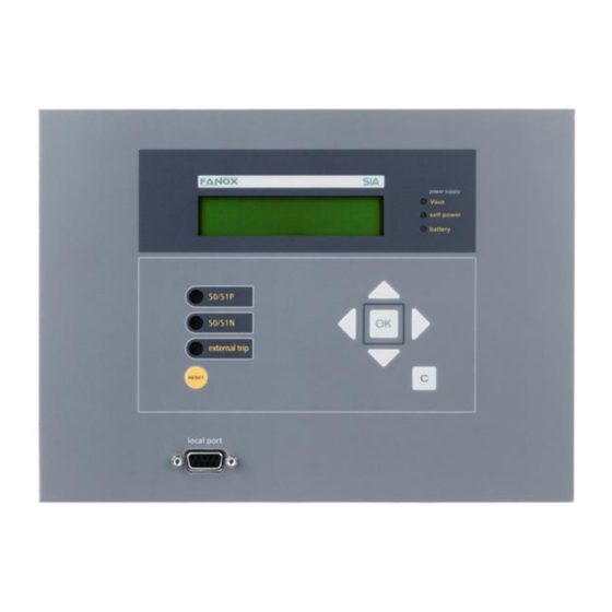
7. USER INTERFACE Leds LCD (2x20 caracteres) magnetic indicators keyboard - Reset magnetic indicators - Events erasing RS232 7.1. Bistable magnetic indicators The front panel is equipped with 3 bistable magnetic indicators which indicate the cause of the last trip. The indicators remain in position even when the equipment looses power, so that the maintenance service can see the cause of the trip even through the equipment is not powered. -
Page 63: Rs232 Communications Port
• Status reading • Measurement reading • Reading and changing settings • Reading and deleting events • Changing the user passwords • Loading settings files • Date-time synchronisation • Checking the versions of the equipment 63 / 117 SIA-D_ www.fanox.com Rev. 07... - Page 64 PASSWORD ACCESS LEVEL 2222 3333 4444 5555 • No password is needed to perform the commands using the HMI. • The SIA-D does not have protected settings. 64 / 117 SIA-D_ www.fanox.com Rev. 07...
-
Page 65: Standby Mode Screen
FANOX If any error is detected by the self-diagnosis, an error message appears in the second line (instead of the word "FANOX”) on the main screen, which can show any of the following information: (see inside self-diagnosis section). • PROTECTION ERROR •... -
Page 66: Communication Parameters
The communications parameters can be viewed holding down the “▲” key from the standby mode screen. COM Settings: 1 19200-8-N-1 • Modbus address • Communication speed • Number of data bits • Parity • Number of stop bits 66 / 117 SIA-D_ www.fanox.com Rev. 07... -
Page 67: Fault Report
” key. From here, press “OK” to access the components that can be tested. "OK mantenido" SIAD---- Menú test s/n? "OK" Introduce clave "OK" "OK" Menú test FANOX (sin protección) >5555 "C" "C" "C" Led Vaux "OK" Led Vaux "C"... -
Page 68: Measurements Menu
The message “>Activations present” appears under the name of the group in the status group menus if any of the statuses in that group are active. The method for navigating through the status menu is shown graphically below. 68 / 117 SIA-D_ www.fanox.com Rev. 07... - Page 69 52 Cerrado "C" 52 Tiempo cierre "C" 52 Error cierre "C" Alarma num aperturas "C" Alarma I2t "C" Exceso num disparos 69 / 117 SIA-D_ www.fanox.com Rev. 07 "OK" "C" "C" Estados CONTROL Com. Local "C" Actividad MMI "C" Selección comando...
-
Page 70: Settings Menu
"OK" (password is already set) Set Password >0 Set Password >5555 "OK" Function Enable NO -> NO Function Enable NO -> YES "OK" Function Enabled y/n? NO -> YES "OK" SETTING CHANGED Function Enable "OK" Function Enable 70 / 117 SIA-D_ www.fanox.com Rev. 07... - Page 71 "C" ---- "C" Tmp Openings x Time ---- "OK" Identification Generals "C" ----- "C" "C" CT Phase Ratio ---- "C" CT Neutro Ratio ---- "C" Frequency 50/60 Hz "C" TT Neutro Ratio ---- 71 / 117 SIA-D_ www.fanox.com Rev. 07...
-
Page 72: Events Menu
The information displayed below the meter name is its value. The password must be entered before attempting to change a counter for the first time. Meter changes are allowed once the password has been entered, until the standby mode screen is 72 / 117 SIA-D_ www.fanox.com Rev. 07... -
Page 73: Commands Menu
To change the associated logical input, press “OK” and use the “▲” and “▼” keys to find the desired physical input. Confirm the choice by pressing “OK”. Go up through the menu levels by pressing the "C" key. 73 / 117 SIA-D_ www.fanox.com Rev. 07... -
Page 74: Output Configuration Menu
“OK”. After the confirmation is displayed on the screen, the index of 1 to 16 associated to the instantaneous status within the physical output configuration is displayed. Go up through the menu levels by pressing the "C" key. 74 / 117 SIA-D_ www.fanox.com Rev. 07... - Page 75 States OUTPUTS "C" "C" not activated/activated Trip Config 2/16: CONTROL "OK" "C" Output 2 Open Breaker "C" not activated/activated Output 3 not activated/activated Conf x/16 :INPUTS "OK" Input 1 "C" Output 4 not activated/activated 75 / 117 SIA-D_ www.fanox.com Rev. 07...
- Page 76 To perform this test, connect a PC with the SICom software program to the SIA-D relay, and check that there are no communication errors. If a laptop computer is used, the connector will probably be a USB. It is important to check the assigned communications port. 76 / 117 SIA-D_ www.fanox.com Rev. 07...
- Page 77 It is recommended that the following safety measures are taken before starting up the facility for the first time, or after a trip event: • FANOX recommends the use of the KitCom accessory with a battery in the front port. This additional energy source allows the relay to be monitored and the trip to function without the need for self power in any breakdown situation.
- Page 78 The length of this time of silence varies depending on the transmission speed, as it is equivalent to 3 characters. The following table shows the generic package format that is valid for transmission and reception. However, each function has its own peculiarities, as will be described further on. 78 / 117 SIA-D_ www.fanox.com Rev. 07...
- Page 79 A frame is terminated when nothing is received for a DEAD TIME time to period of 3,5 bytes. It means: transmit 15 ms at 2400 bps 3,5 Bytes 2 ms at 19200 bps ...etc. 79 / 117 SIA-D_ www.fanox.com Rev. 07...
- Page 80 Indicates an error occurred in the slave while trying to execute the request of the master. ACKNOWLEDGE Generic recognition. SLAVE DEVICE BUSY The slave is busy and unable to perform the required operation. NEGATIVE ACKNOWLEDGE Generic non-recognition. 80 / 117 SIA-D_ www.fanox.com Rev. 07...
- Page 81 String: In length variable character chain. Final of String marked with ‘\0’. E. g.: “ABC” 0x41x42x43x00..MILIS Minutes(passed since 00:00 of 1/1/2000)(LONG).milliseconds(UINT) Year(UINT).month(UCHAR).day(UCHAR).hour(UCHAR).minutes(U CHAR).seconds(UCHAR).hundredth(UCHAR).thousandth(UINT) CONT Directory(UINT).Value(DWORD).Description(ASCII20) EVENT Criteria Directory(UINT).Event Identifier(UINT).Value(UINT).Associated Measure(UINT).Date and Time(FH) EVENTO Antiquity(UINT).Event(EVENT) CCRIT Criteria Number(UINT).Criteria Directory(UINT).Descriptive text(ASCII8) 81 / 117 SIA-D_ www.fanox.com Rev. 07...
- Page 82 Read and Delete the oldest EVENT See events list Event Delete All Events dummy Write the Directory of the UINT See protection criteria Protection Criterion Read of the Protection PEST See protection status 82 / 117 SIA-D_ www.fanox.com Rev. 07...
- Page 83 General Status Map Trip bit-0 External Trip Input Active bit-1 Auxiliary Supply bit-2 Self-power bit-3 9Vcc Supply bit-4 Error No Trip Voltage bit-5 Frequency 50 Hz bit-6 RESERVED bit-7 RESERVED bit-8 RESERVED bit-9 83 / 117 SIA-D_ www.fanox.com Rev. 07...
- Page 84 Change of values in E2prom bit-27 Error registering Events bit-28 RESERVED bit-29 RESERVED bit-30 There are New Events bit-31 9.7. Counters Map Number of circuit breaker openings Number of Amps Accumulated during the circuit breaker openings 84 / 117 SIA-D_ www.fanox.com Rev. 07...
- Page 85 51202 =200*256+2 General 51713 = 202*256+1 Fuse + Switchgear 52225 = 204*256+1 Tripping Bus: 50P, 51P, 50N, 51N 52226 = 204*256+2 Tripping Bus: 50P, 51P, 50N, 51N, 67N1 and 67N2 64770 = 253*256+2 Inputs 85 / 117 SIA-D_ www.fanox.com Rev. 07...
- Page 86 ISO 9001:2008 65027 = 254*256+3 Outputs 13313 = 52*256+1 63745 = 249*256+1 Local Communication ModBus 86 / 117 SIA-D_ www.fanox.com Rev. 07...
- Page 87 Phase C pick-up bit-3 Pick-up bit-4 RESERVED bit-5 RESERVED bit-6 RESERVED bit-7 RESERVED bit-8 Phase A trip bit-9 Phase B trip bit-10 Phase C trip bit-11 Trip bit-12 RESERVED bit-13 RESERVED bit-14 RESERVED bit-15 RESERVED 87 / 117 SIA-D_ www.fanox.com Rev. 07...
- Page 88 Phase C pick-up bit-3 Pick-up bit-4 RESERVED bit-5 RESERVED bit-6 RESERVED bit-7 RESERVED bit-8 Phase A trip bit-9 Phase B trip bit-10 Phase C trip bit-11 Trip bit-12 RESERVED bit-13 RESERVED bit-14 RESERVED bit-15 RESERVED 88 / 117 SIA-D_ www.fanox.com Rev. 07...
- Page 89 RESERVED bit-1 RESERVED bit-2 RESERVED bit-3 RESERVED bit-4 Pick-up bit-5 RESERVED bit-6 RESERVED bit-7 RESERVED bit-8 RESERVED bit-9 RESERVED bit-10 RESERVED bit-11 RESERVED bit-12 Trip bit-13 RESERVED bit-14 RESERVED bit-15 RESERVED 89 / 117 SIA-D_ www.fanox.com Rev. 07...
- Page 90 RESERVED bit-1 RESERVED bit-2 RESERVED bit-3 RESERVED bit-4 Start bit-5 RESERVED bit-6 RESERVED bit-7 RESERVED bit-8 RESERVED bit-9 RESERVED bit-10 RESERVED bit-11 RESERVED bit-12 Trip bit-13 RESERVED bit-14 RESERVED bit-15 RESERVED 90 / 117 SIA-D_ www.fanox.com Rev. 07...
- Page 91 67N1 bit-1 V0 Active bit-2 Directionality bit-3 RESERVED bit-4 Start up bit-5 RESERVED bit-6 RESERVED bit-7 RESERVED bit-8 RESERVED bit-9 RESERVED bit-10 RESERVED bit-11 RESERVED bit-12 Trip bit-13 RESERVED bit-14 RESERVED bit-15 RESERVED 91 / 117 SIA-D_ www.fanox.com Rev. 07...
- Page 92 50P Block Tripping bit-1 51P Block bit-2 50N Block bit-3 51N Block bit-4 67N1 Block bit-5 67N2 Block bit-6 50P Block Signalling bit-7 51P Block Signalling bit-8 50N Block Signalling bit-9 51N Block Signalling 92 / 117 SIA-D_ www.fanox.com Rev. 07...
- Page 93 ISO 9001:2008 bit-10 67N1 Block Signalling bit-11 67N2 Block Signalling bit-12 RESERVED bit-13 RESERVED bit-14 RESERVED bit-15 RESERVED 93 / 117 SIA-D_ www.fanox.com Rev. 07...
- Page 94 Local communication active bit-22 Default Settings Error bit-23 E2prom Error bit-24 RESERVED bit-25 RESERVED bit-26 RESERVED bit-27 Changing E2prom values bit-28 Events records error bit-29 RESERVED bit-30 RESERVED bit-31 There are New Events 94 / 117 SIA-D_ www.fanox.com Rev. 07...
- Page 95 Phase B blocking bit-2 Phase C blocking bit-3 Blocking bit-4 RESERVED bit-5 RESERVED bit-6 RESERVED bit-7 RESERVED bit-8 RESERVED bit-9 RESERVED bit-10 RESERVED bit-11 RESERVED bit-12 RESERVED bit-13 RESERVED bit-14 RESERVED bit-15 RESERVED 95 / 117 SIA-D_ www.fanox.com Rev. 07...
- Page 96 Input Phase Blocking bit-3 Input Neutral Blocking bit-4 Input External Trip bit-5 Input Oscillography Start bit-6 RESERVED bit-7 RESERVED bit-8 RESERVED bit-9 RESERVED bit-10 RESERVED bit-11 RESERVED bit-12 RESERVED bit-13 RESERVED bit-14 RESERVED bit-15 RESERVED 96 / 117 SIA-D_ www.fanox.com Rev. 07...
- Page 97 Outputs 2 bit-2 Outputs 3 bit-3 Outputs 4 bit-4 RESERVED bit-5 RESERVED bit-6 RESERVED bit-7 RESERVED bit-8 RESERVED bit-9 RESERVED bit-10 RESERVED bit-11 RESERVED bit-12 RESERVED bit-13 RESERVED bit-14 RESERVED bit-15 RESERVED 97 / 117 SIA-D_ www.fanox.com Rev. 07...
- Page 98 RESERVED bit-6 RESERVED bit-7 RESERVED bit-8 RESERVED bit-9 RESERVED bit-10 RESERVED bit-11 RESERVED bit-12 RESERVED bit-13 RESERVED bit-14 RESERVED bit-15 RESERVED bit-16 Command selection bit-17 Open circuit breaker bit-18 Close circuit breaker 98 / 117 SIA-D_ www.fanox.com Rev. 07...
-
Page 99: Events List
Pick-up Trip 38661 Pick-up Trip 13313 Reset Error Open Opening Open Error Close Closing Close Error Too many open numbers Too may Amps accumulated Too many open numbers per time Contact 52-A activated 99 / 117 SIA-D_ www.fanox.com Rev. 07... - Page 100 Change of values in E2prom Error registering Events There are New Events Auxiliary Supply Self-power 12Vdc Supply Error No Trip Voltage External Trip Input Active Measure error 48Vdc power supply alarm 64770 Input 52a Inputs 100 / 117 SIA-D_ www.fanox.com Rev. 07...
-
Page 101: Settings Map
0,01 Operating 3013 5013 FLOAT 0,02 300,00 0,01 time 3014 5014 DENUM NOSI Permission 3015 5015 FLOAT 0,10 30,00 0,01 Operating 3016 5016 FLOAT 0,02 300,00 0,01 time 3017 5017 DENUM NOSI Permission 101 / 117 SIA-D_ www.fanox.com Rev. 07... - Page 102 0,02 300,0 0,01 time 3038 5038 DENUM NOSI 67N1 Direccionality Si/No Residual 3039 5039 FLOAT 67N1 4,00 110,00 Voltage Operating 3040 5040 LONG 67N1 º Angle Half-cone 3041 5041 LONG 67N1 º Angle 102 / 117 SIA-D_ www.fanox.com Rev. 07...
- Page 103 300,0 0,01 Tripping Bus time Model without 67N Application 3035 5035 DENUM Tripping Bus (2*) 50P blocking 3036 5036 DENUM NOSI Tripping Bus permission 51P blocking 3037 5037 DENUM NOSI Tripping Bus permission 103 / 117 SIA-D_ www.fanox.com Rev. 07...
- Page 104 Neutral 3041 5041 FLOAT 300,0 0,01 Tripping Bus blocking time Phase block 3042 5042 FLOAT signalling 300,0 0,01 Tripping Bus time Neutral block 3043 5043 FLOAT signalling 300,0 0,01 Tripping Bus time 104 / 117 SIA-D_ www.fanox.com Rev. 07...
- Page 105 Curve IEC 244-4/BS-142 inverse IEC 244-4/BS-142 very inverse IEC 244-4/BS-142 extremely inverse Definite Time (2*) Values of enum of application setting on tripping bus: Value Application Not activated Feeder Supply Feeder and supply 105 / 117 SIA-D_ www.fanox.com Rev. 07...
- Page 106 H checksum L And the SIA will reply OK: address function H start address L start address Number of H registers Number of L registers Number of Bytes checksum H checksum L 106 / 117 SIA-D_ www.fanox.com Rev. 07...
- Page 107 And the SIA will reply with the IA, IB, IC and I0 measurements in FLOAT format: address function Number of Bytes 00,00,00,00 Measurement IA 00,00,00,00 Measurement IB 00,00,00,00 Measurement IC 00,00,00,00 Measurement IN checksum H checksum L 107 / 117 SIA-D_ www.fanox.com Rev. 07...
- Page 108 And the SIA will reply with: address function Number of Bytes 00,09 50PStatus 00,00 51PStatus 00,00 50NStatus 00,00 51NStatus 00,00,00,D2 GeneralStatus 80,21 Inputs Status 00,00 Outputs Status 00,03 COM Status RESERVED checksum H checksum L 00,00,00,01,00,00,00,00,……,7C,B1,0A,AF,DD 108 / 117 SIA-D_ www.fanox.com Rev. 07...
- Page 109 ISO 9001:2008 10. APPENDIX 10.1. Identification Date : ............................. Manager : ..........................Substation : ..........................Circuit : ........................... Model : ........................... Serial no. : ..........................Software Versions : ..........................Model: ........................109 / 117 SIA-D_ www.fanox.com Rev. 07...
- Page 110 4O + 4I With volatil RAM memory With non-volatil RAM memory (events) With non-volatil RAM memory (events + oscilos) English, Spanish, French English, Spanish, French, Turkish English, Spanish, French, Polish First Version Second Version 110 / 117 SIA-D_ www.fanox.com Rev. 07...
- Page 111 CT Ratio: Phase CT Ratio: ……………………..……………………………………………………… Neutral CT Ratio: …………………………......……………………………………… Neutral TT Ratio:………………………....…………………………………..………… 10.4.2. 50P: Permission Enabled Disabled Tap......…………… Operating Time..………..s 10.4.3. 50N: Permission Enabled Disabled Tap......…………… Operating Time..………..s 111 / 117 SIA-D_ www.fanox.com Rev. 07...
- Page 112 Half-cone Angle ……………….. º 10.4.7. 67N2 Permission Enabled Disabled Tap.…………………………xIn Operating Time ……………… Directional Residual Voltage ……………….. V Operating Angle …………… º Half-cone Angle ……………….. º 10.4.8. Breaker: Permission Enabled Disabled Blocking level.....………… 112 / 117 SIA-D_ www.fanox.com Rev. 07...
-
Page 113: Circuit Breaker
Phase signalling time: ………………………………… s Neutral signalling time: ………………………………… s 10.5. Input configuration Input 1 Input 2 Input 3 Input 4 No configuration 52 a 52 b Phase blocking Neutral blocking External trip Oscillograph start 113 / 117 SIA-D_ www.fanox.com Rev. 07... -
Page 114: Output Configuration
ISO 9001:2008 10.6. Output configuration Output 1 Output 2 Output 3 Output 4 Nº de OR 114 / 117 SIA-D_ www.fanox.com Rev. 07... - Page 115 ISO 9001:2008 10.7. Comments …………….....……………………………………………………………………………..… …………….....……………………………………………………………………………..… ……………....……………………………………………………………………………..… …………….....……………………………………………………………………………..… …………….....……………………………………………………………………………..… Person in charge of commissioning………..……..…………..Date……….....… Maintenance performed on the………………….. by ………..………………………………….. 115 / 117 SIA-D_ www.fanox.com Rev. 07...
- Page 116 …………………………………………………………………………………………………..…… …………………………………………………………………………………………………..…… …………………………………………………………………………………………………..…… …………………………………………………………………………………………………..…… …………………………………………………………………………………………………..…… …………………………………………………………………………………………………..…… …………………………………………………………………………………………………..…… …………………………………………………………………………………………………..…… …………………………………………………………………………………………………..…… …………………………………………………………………………………………………..…… …………………………………………………………………………………………………..…… …………………………………………………………………………………………………..…… …………………………………………………………………………………………………..…… …………………………………………………………………………………………………..…… …………………………………………………………………………………………………..…… …………………………………………………………………………………………………..…… …………………………………………………………………………………………………..…… …………………………………………………………………………………………………..…… …………………………………………………………………………………………………..…… …………………………………………………………………………………………………..…… …………………………………………………………………………………………………..…… …………………………………………………………………………………………………..…… …………………………………………………………………………………………………..…… …………………………………………………………………………………………………..…… …………………………………………………………………………………………………..…… …………………………………………………………………………………………………..…… …………………………………………………………………………………………………..…… …………………………………………………………………………………………………..…… …………………………………………………………………………………………………..…… …………………………………………………………………………………………………..…… …………………………………………………………………………………………………..…… …………………………………………………………………………………………………..…… …………………………………………………………………………………………………..…… 116 / 117 SIA-D_ www.fanox.com Rev. 07...
- Page 117 ISO 9001:2008 FANOX ELECTRONIC S.L. Parque Tecnológico de Bizkaia Astondo bidea, Edif. 604 48160 DERIO ESPAÑA + 34 94 471 14 09 Tel. + 34 94 471 05 92 power-td fanox.com www.fanox.com 117 / 117 SIA-D_ www.fanox.com Rev. 07...
Need help?
Do you have a question about the SIA D and is the answer not in the manual?
Questions and answers