Table of Contents
Advertisement
Quick Links
Advertisement
Table of Contents

Related Manuals for Markusson Grindomatic V12


Summary of Contents for Markusson Grindomatic V12
- Page 1 Original Instruction Manual Grindomatic www.markusson.se...
-
Page 2: Table Of Contents
5.3 Operating the machine ..23 5.4 Depth gauge grinding ..24 © 2017 Markusson Professional Grinders AB - All rights reserved. 2 Grindomatic 201708 EN... -
Page 3: Introduction
Introduction Grindomatic 1 Introduction 1.1 Important user information WARNING Before you install, operate or do maintenance on the machine, you must read the safety information in this manual. Obey the instructions in this manual to prevent injuries or damage to the equipment. 1.2 About this manual This user manual describes how to safely install, operate, and perform basic maintenance on the Grindomatic Auto Chain Grinder chain sharpening machine. -
Page 4: Nameplate
Introduction Grindomatic 1.5 Nameplate This nameplate is placed on the Grindomatic Auto Chain Grinder’s grinding head. 1.6 Recycling information This symbol shows that electrical and electronic equipment must not be disposed of as unsorted municipal waste. It must be collected separately. Recycle according to current local rules and regulations. 4 Grindomatic 201708 EN... -
Page 5: Safety
Safety Grindomatic 2 Safety 2.1 Safety notices This section contains safety information for the Grindomatic Auto Chain Grinder. This manual contains WARNINGS, CAUTIONS, and IMPORTANT notes that are applicable for the safe operation of the machine. WARNING A warning tells you about conditions that can cause injury or death, if you do not obey the instructions. -
Page 6: Signs And Symbols
Safety Grindomatic 2.3 Signs and symbols See the table below for information about the signs and symbols on The Grindomatic Auto Chain Grinder: Sign/Symbol Description Always wear protective glasses and ear protection when using the machine. Always wear protective gloves when using the machine. Warning! A warning tells you about conditions that can cause injury or death, if you do not obey the instructions. -
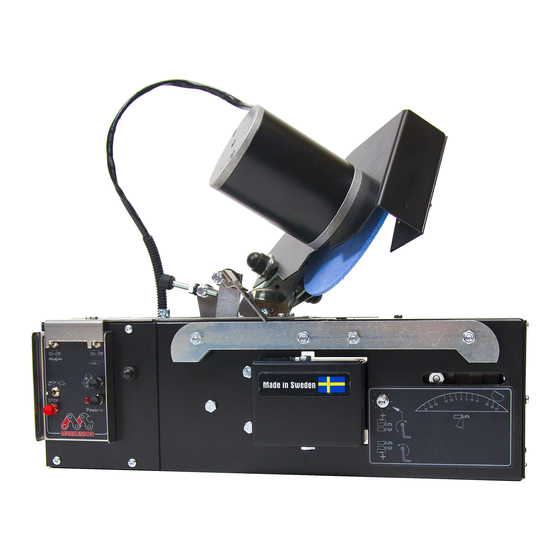
Page 7: Product Description
Product Description Grindomatic 3 Product Description 3.1 Product overview The Grindomatic Auto Chain Grinder is a machine that sharpens chains. The machine can sharpen chains (3/8”, 3/8” Low Profile, .325”, and .404” pitch) for power saws, forestry machines, and harvesters. 3.2 Front view Part Description... -
Page 8: Back View
Product Description Grindomatic 3.3 Back view Part Description Pitch adjustment wing Adjusts the pitch. Grinding head cover and grinding Protects the grinding head and grinding wheel; it also protects the wheel guard user from sparks during grinding. Shows the top-plate angle on a scale from 0-35°. Default: 30°. It is Top-plate angle scale set using the top-plate angle screw (O in Front view illustration). -
Page 9: Grinding Head
Product Description Grindomatic 3.4 Grinding head The grinding wheel on the grinding head sharpens the chains. The type of wheel, the top-plate angles, the settings of the grinding head, and the profiling of the grinding wheel all determine how the chain is sharpened. Part Description Grinding wheel... -
Page 10: Controls
Product Description Grindomatic 3.5 Controls Part Description ON: starts the chain feed, so that the chain moves in a forward Chain pusher switch direction. OFF: Stops the chain feed. Sets the grinding speed. Low speed: Grinds the chain at low speed in a pulsing motion to Grinding speed knob avoid that the chain gets burned. -
Page 11: Grinding Speed Knob
Product Description Grindomatic 3.5.1 Grinding speed knob The grinding speed knob sets the speed of the grinding wheel. The speed can be set to different speeds to grind 0 mm to 4 mm of the cutting teeth. At low speed, grinding is done in a pulsing motion. 3.6 Chain overview This section describes the definitions for the parts of a normal chain. -
Page 12: Technical Data
Product Description Grindomatic 3.7 Technical data Parameter Value Supply voltage 12-15 V DC Power 144 W Current 12 A Over-current protection Automatic fuse type ptc Rotation speed 3250 rpm Peripheral speed 25 m/s Grinding wheel dimensions Outer diameter (OD) × Width (W) × Inner diameter (ID): (for the grinding wheels included in the •... -
Page 13: Installation
4.3 Unpacking the machine Note: For a video demonstration of how to unpack, assemble, install, and operate the machine, visit markusson.se. Unpack the crates. Note: Keep the delivery crates and packing materials. Pack the machine in them if it is moved or sent for service. -
Page 14: Bench-Mounting The Machine
AC/DC converter unit (optional) to the machine, The correct wheel size for a particular plug in the black and red power cable into the Markusson saw chain can be found in control panel through the slot on the left hand several sources: this manual, the back side of the machine. - Page 15 Installation Grindomatic Next, insert the appropriate wheel onto the hub Once the grinding wheel has been verified, and, using moderate pressure with your hands, you’re ready to begin the install. secure the wheel attachment nut to hold the Start by removing the grinding wheel shield (C) wheel in place.
-
Page 16: Test The Machine Before First Use
Installation Grindomatic 4.6 Test the machine before first use Make sure that all packing materials are removed. Make sure that the wires and when used with a stand, air hoses are correctly connected. Make sure that the machine is securely mounted. -
Page 17: Operation
5.2 Preparing for operation Note: For a video demonstration of how to install and operate the machine, go to Markusson.se. Make sure that the grinding wheel does not 5.2.1 Preparing the grinding wheel vibrate or wobble. -
Page 18: Setting The Head-Tilt Angle
Operation Grindomatic Set the grinding wheel switch to OFF. Turn the grinding head to set the desired head-tilt angle (50-90°) on the head-tilt angle scale. The default head-tilt angle is 60°. Use the profile template to verify that the grinding wheel has the same profile as the type Tighten the head-tilt angle knob. -
Page 19: Inserting The Chain
Operation Grindomatic Press the grinding head positioning button to Place the chain, with the cutter to the left of the move the grinding head in both directions and depth gauge, into the groove on the chain vise. make sure that the top-plate angles are the same. -
Page 20: Making The Grinding Settings
Operation Grindomatic Loosen the chain pitch wing-nut and move it to 5.2.5 Making the grinding settings the correct pitch position. Tighten it again. Press the power button to turn on the machine. Press the grinding head positioning button to Note: Adjusting the pitch is not the same thing move the grinding head so that it is tilted in the as adjusting the cutting tooth length (see correct start position for the next cutting link to... - Page 21 Operation Grindomatic Repeat steps 5-8 until the chain pusher stops in The grinding depth for gullets is recommended the correct position. by the chain manufacturer. To set it, turn the grinding depth knob, located on the back of the CAUTION If the pitch is not correctly set, grinding head: the chain will be pushed into an incorrect sharpening position.
- Page 22 Operation Grindomatic The diameter of the grinding wheel decreases • counter-clockwise, to grind less, resulting in a when it is used. To maintain the grinding longer cutter top plate.. proportions, the grinding wheel position must be changed when the grinding wheel has been worn.
-
Page 23: Operating The Machine
Note: For a video demonstration of how to install grinding stops. and operate the machine, go to markusson.se. Lift the grinding head to its most upright Note: Discard the chain when the longest part of the position. -
Page 24: Depth Gauge Grinding
Change the grinding wheel to 6.4mm See section 4.5, “Installing the grinding wheel”. • Use a Markusson flat file to set the height of the depth gauge. Once you have set the Shape the edges of the grinding wheel to make depth gauge, refer back to the template to sure that the shape is correct. - Page 25 Operation Grindomatic Adjust the feed so that the grinding wheel touches the depth gauge. Make the grinding settings according to the manufacturer’s recommendations. Attach the stop clamp on a tie-strap between a double-link or a joint-link. Begin grinding to the left of the stop clamp. Grindomatic 201708 EN 25...
-
Page 26: Maintenance And Service
Maintenance and Service Grindomatic 6 Maintenance and Service 6.1 Safety during maintenance WARNING Make sure that the power is turned off before you install, operate or do maintenance on the machine. WARNING Before you install, operate or do maintenance on the machine, you must read the safety information in this manual. -
Page 27: Changing The Grinding Wheel And Fitting The Grinding Wheel Guard
Maintenance and Service Grindomatic 6.3 Changing the grinding wheel and Hold the grinding wheel and loosen the nut (B). fitting the grinding wheel guard WARNING Before a chain is sharpened, make sure that the grinding wheel is not cracked, does not vibrate or wobble. -
Page 28: Fastening The Chain Vise
Maintenance and Service Grindomatic 6.4 Fastening the chain vise 6.5 Checking and adjusting the wire The chain vise needs to be fastened if the chain is Note: If the wire is not correctly set, the grinding not fixed during sharpening. machine will not operate correctly. -
Page 29: Service
Maintenance and Service Grindomatic Set the chain pusher switch to ON. To set the wire so that the lifting arm meets the flange: • for a shorter time: turn the two nuts (D) in the direction towards the machine. • for a longer time: turn the two nuts (D) in the direction from the machine. -
Page 30: Troubleshooting
Troubleshooting Grindomatic 7 Troubleshooting 7.1 Troubleshooting procedure Make sure that the machine has sufficient power. Read section 7.3, “Issues” to find a description of the issue. Perform the recommended corrective procedures. Perform a sharpening test, see instruction in section 7.2, “Sharpening test”. If the problem persists after corrective procedures, contact your regional sales representative to reach your service team. -
Page 31: Issues
Troubleshooting Grindomatic 7.3 Issues Issues Possible cause Corrective procedure The grinding head “falls” without The wire is worn and needs to be See section 6.5, “Checking and adjusting slowing down before it touches the adjusted. wire”. cutter. The lengths of the right and left cutters The equal cutting teeth knob is See step 13 of section 5.2.5, “Making the are not the same. -
Page 32: Accessories And Spare Parts
Accessories and Spare Parts Grindomatic 8 Accessories and Spare Parts 8.1 Ordering information Contact your regional sales representative to order spare parts or accessories. Contact information to the manufacturer is located on the back cover of this user manual. 8.2 List of accessories. Accessory Description Order Number... -
Page 33: Spare Parts
Accessories and Spare Parts Grindomatic 8.3 Spare parts 24 26 Spare Part Order Number Spare Part Order Number Adjuster complete 12-047 Control panel assembly 12-033M Chain lock 12-031 PDE bearing 12-032 Holder 13-114 Control unit (PCB) 12-033BUL Spring 12-045 Bolt M6 x 30 12-034 Chain pusher 12-044C... - Page 34 Accessories and Spare Parts Grindomatic Order Spare Part Spare Part Order Number Number Adjuster assembly 12-056 Axis 12-063 Grinding head cover 13-116M Degree beam 13-126 Grinding wheel guard 12-058M Wire 12-066 Grinding wheel centering knob assembly 13-117 Ball bearing 6000ZZ 12-065 Grinding wheel nut 13-118...
-
Page 35: Converter
Accessories and Spare Parts Grindomatic 8.4 Converter Spare Part Order Number Converter 115 V Converter 230 V 8.5 Stand Spare Part Order Number Stand 14-501 14-506 Pneumatic chain tensioner Grindomatic 201708 EN 35... -
Page 36: Pneumatic Chain Tensioner
Accessories and Spare Parts Grindomatic 8.6 Pneumatic chain tensioner The purpose of the pneumatic chain tensioner is to attach and secure the chain in the correct operating position. It also keeps the chain properly tensioned during grinding. Part Description Where the tensioner slides up and down. The tensioner is moved Tensioner rail to fit chains of different lengths. -
Page 37: Assembling The Stand
Assembling the stand Grindomatic 9 Assembling the stand CAUTION The Grindomatic Auto Chain Grinder machine must always be safely attached to the stand. Make sure that it is safely attached. To mount the grinder on the stand, begin by assembling the stand. The stand comes in 4 pieces: two sides, one base and one front piece. -
Page 38: Assembling The Pneumatic Chain Tensioner
Assembling the stand Grindomatic Start by placing the base piece on the floor. To complete the assembly of the stand, bolt the Place the front piece on top of the base piece side support first to the base and then to the by aligning the holes they have on the front front piece. - Page 39 Assembling the stand Grindomatic Then insert the rod through the unit and insert Do not completely tighten the bolt. Once the the bottom part of the rod onto the base of the bolt is in place, slide it into the slot located at stand.
- Page 40 AC/DC converter to the back of the stand Note: For best performance, use the converter by aligning the two holes located at the top and provided by Markusson. the bottom of the converter to the holes on the WARNING Put the power converter where stand.
-
Page 41: Using The Chain Tensioner
Assembling the stand Grindomatic 9.2 Using the chain tensioner Lower the tensioner arm to its bottom position. Loosen the locking handle and move the tensioner upward or downward to make enough room to position the chain. Lift the tensioner arm (there is a quick release function) and place the chain below the tensioner roll. - Page 42 Assembling the stand Grindomatic Tighten the locking handle to secure the chain. If the chain tension is too loose, repeat the procedure. Note: If you need to fit longer chains, you can order a telescopic chain extension kit. See section 8, “Accessories and Spare Parts” Gently press the chain with your hand to test the tension.
-
Page 43: Declaration Of Conformity
Declaration of conformity Grindomatic 10 Declaration of conformity EC DECLARATION OF CONFORMITY Markusson Professional Grinders AB Tegelbruksvägen 3 762 31 Rimbo Sweden Certifies that the construction and manufacturing of the product Grindomatic conforms to the following directives, regulations and standards:... - Page 44 Markusson Professional Grinders AB Tegelbruksvägen 3 | SE 762 31 RIMBO www.markusson.se...
Need help?
Do you have a question about the Grindomatic V12 and is the answer not in the manual?
Questions and answers