Table of Contents
Advertisement
Advertisement
Table of Contents
Troubleshooting

Related Manuals for Markusson Triplematic


Summary of Contents for Markusson Triplematic
- Page 1 Original Instruction Manual Triplematic www.markusson.se...
-
Page 2: Table Of Contents
....20 4.8 Test the machine before first use . . . 22 © 2017 Markusson Professional Grinders AB - All rights reserved. 2 Triplematic 201708 EN... -
Page 3: Introduction
Obey the instructions in this manual to prevent injuries or damage to the equipment. 1.2 About this manual This user manual describes how to safely install, operate, and perform basic maintenance on the Triplematic Auto Chain Grinder chain sharpening machine. This manual also describes the parts of the machine, and it shows different accessories and spare parts that are available. -
Page 4: Nameplate
Introduction Triplematic 1.5 Nameplate This nameplate is placed on the Triplematic Auto Chain Grinder’s grinding head. 1.6 Recycling information This symbol shows that electrical and electronic equipment must not be disposed of as unsorted municipal waste. It must be collected separately. Recycle according to current local rules and regulations. -
Page 5: Safety
WARNING Attach air hoses and cables with cable clamps, to make sure no one trips over them. CAUTION The Triplematic machine must always be attached to the stand. Make sure that it is safely attached. CAUTION Only use accessories that are supplied or approved by the manufacturer. -
Page 6: Signs And Symbols
Safety Triplematic 2.3 Signs and symbols See the table below for information about the signs and symbols on The Triplematic Auto Chain Grinder: Sign/Symbol Description Always wear protective glasses and ear protection when using the machine. Always wear protective gloves when using the machine. -
Page 7: Product Description
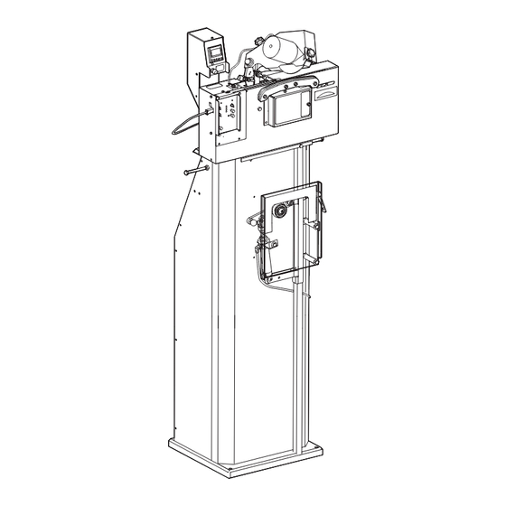
3 Product Description 3.1 Product overview The Triplematic Auto Chain Grinder is a machine that sharpens chains. The machine can sharpen chains (up to .404” pitch) for power saws, forestry machines, and harvesters. A pneumatic chain tensioner is attached to the stand. -
Page 8: Front View
Advances the chain through the vise. Chain vise Positions the chain as it moves in the machine. Left-right alignment screw Sets the right and left cutters to equal length. Top-plate angle screw Sets the top-plate angle, 0-35°. Default 30°. 8 Triplematic 201708 EN... -
Page 9: Back View
Adjusts the wire that controls the vertical movement of the grinding Wire adjustment knobs head. Head-tilt angle nut Sets the head-tilt angle on the head-tilt angle scale. (D) Depth gauge height knob Sets the height of the depth gauge. Triplematic 201708 EN 9... -
Page 10: Grinding Head
Grinding wheel Grinds the chain. Grinding wheel nut Keeps the grinding wheel in place. Grinding wheel guard Protects the user and grinding wheel when the chain is sharpened. 2 screws Secures the grinding wheel guard in place. 10 Triplematic 201708 EN... -
Page 11: Pneumatic Chain Tensioner
Allows the user to tension or release the chain faster than if the Tensioner arm/Quick release locking handle is used (quick release function). Pneumatic piston nut Holds the pneumatic piston in place. Air hose Supplies the tensioner with pneumatic air. Pneumatic piston. Gives flexibility to the tensioner. Triplematic 201708 EN 11... -
Page 12: Controls
Indicates potential problems with the machine. See section 8.4, Troubleshooting indicators “Troubleshooting indicators”. Changes the angle of the grinding head from left to right, or vice Grinding head positioning button versa. Power Button Turns on the machine. 12 Triplematic 201708 EN... -
Page 13: Counter
The part of the cutter that cuts chain. Gullet The space between the cutting tooth and the depth gauge. Rivet hole A hole where the rivet is placed. Depth gauge The front part of the cutter. Triplematic 201708 EN 13... -
Page 14: Technical Data
Length (L) x Width (W) x Height (H): 345 mm x 360 mm x 1070 mm (13.5” x 14.1” x 42.1” ) Weight of the machine 17.5 kg Weight, stand 33 kg Compressed air supply pressure 5-8 bar 14 Triplematic 201708 EN... -
Page 15: Installation
4.3 Unpack the machine Note: For a video demonstration of how to unpack, assemble, install, and operate the machine, visit Markusson.se Unpack the crates. Note: Keep the delivery crates and packing materials. Pack the machine in them if it is moved or sent for service. -
Page 16: Assembling The Stand
Installation Triplematic 4.4 Assembling the stand CAUTION The Triplematic Auto Chain Grinder machine must always be attached to the stand. Make sure that it is safely attached. To mount the grinder on the stand, begin by assembling the stand. The stand comes in 4 pieces: two sides, one base and one front piece. -
Page 17: Assembling The Pneumatic Chain Tensioner
To assemble the pneumatic chain tensioner, lay the intersection of two pieces to create the side stand on the floor with the front piece facing up. support piece. First, attach the handle to the pneumatic chain tensioner. Triplematic 201708 EN 17... - Page 18 Insert the provided long bolts into the holes located on both sides of the stand and fix them in place with a 0.5" (13 mm) wrench. 18 Triplematic 201708 EN...
- Page 19 3 holes located at the back of the machine with the bolts and nuts provided. WARNING Attach air hoses and cables with cable clamps to make sure no one trips over them. Triplematic 201708 EN 19...
-
Page 20: Bench-Mounting The Machine
The correct wheel size for a particular Markusson saw chain can be found in several sources: this manual, the back of the Markusson chain packaging, Markusson Maintenance and Safety Manual, or online at Markusson.se... - Page 21 WARNING Over-tightening the wheel can cause it to break. Finally, reposition the shield and secure it in place with the retaining screw. WARNING Never start the grinder without the wheel guards in place. Triplematic 201708 EN 21...
-
Page 22: Test The Machine Before First Use
Perform a sharpening test on the machine to ensure it functions correctly. See section 8.2, “Sharpening test”. 22 Triplematic 201708 EN... -
Page 23: Operation
5.2 Prepare for operation Note: For a video demonstration of how to install and operate the machine, go to Markusson.se. 5.2.1 Prepare the grinding wheel WARNING Before a chain is sharpened, make sure that the grinding wheel is not cracked, does not vibrate or wobble. -
Page 24: Set The Head-Tilt Angle
Use the hex key (provided with the machine) to loosen the top-plate angle screw up to three turns. Repeat steps 4-8 until the grinding wheel profile is the same as the selected profile on the profile template. 24 Triplematic 201708 EN... -
Page 25: Insert The Chain
(A) a 1/2-turn at the time. CAUTION! If the chain does not run freely, or if the chain is forced down into the groove by pressure from the air tensioner, it can get caught during the feed. Triplematic 201708 EN 25... - Page 26 12.7 mm between the pneumatic-piston nut and pneumatic piston, where the piston should be visible. Lift the tensioner arm (there is a quick release function) and place the chain below the tensioner roll. 26 Triplematic 201708 EN...
-
Page 27: Make The Grinding Settings
Press the grinding head positioning button to move the grinding head so that it is tilted in the correct start position for the next cutting link to be ground. Lift the grinding head to its uppermost position. Triplematic 201708 EN 27... - Page 28 Note: Adjusting the pitch is not the same thing sharpening position. This may result in a as adjusting the cutting tooth length (see damaged chain. number 13 below). Set the chain pusher switch to ON. The chain pusher arm now advances the chain forward. 28 Triplematic 201708 EN...
- Page 29 Observe if the grinding depth of right and left gullets are equal for final adjustment. Grinding wheel diameter: Scale: 5.9" (150 mm) (new grinding wheels) 5.5" (140 mm) 5.1" (130 mm) Triplematic 201708 EN 29...
- Page 30 If required: Turn the chain pusher adjustment to make minor adjustments for the grinding length. • Use an Markusson flat file to set the height of the depth gauge. Once you have set the depth gauge, refer back to the template to make sure it meets the correct specifications.
-
Page 31: Use Skip Tooth Mode
Use a finger to move plate B in the direction of the “Standard” arrow, until it enters its locked 5.2.6 Use skip tooth mode position. Triplematic Auto Chain Grinder has 2 chain pusher modes: • The standard mode, used for sharpening standard chains. - Page 32 When the set number of links are sharpened, the chain feeding and the grinding stops. If required: Adjust the settings or reposition the grinding head on the right or left side to sharpen a double-link. 32 Triplematic 201708 EN...
- Page 33 Set the grinding wheel switch to OFF. IMPORTANT Grinding dust can interfere with the machine’s operation. Clean the machine daily to remove all of the grinding dust. Use a vacuum cleaner, brush or similar to clean the machine. Triplematic 201708 EN 33...
-
Page 34: Maintenance And Service
Check and adjust the wire. Once every 3 months, depending on See section 7.6, “Check and adjust the wire”. usage. Adjust the chain lock. When the chain is loose during See section 7.5, “Adjust the chain lock”. operation. 34 Triplematic 201708 EN... -
Page 35: Change The Grinding Wheel And Fit The Grinding Wheel Guard
Turn the depth gauge height knob: If the grinding wheel guard is already attached: Loosen the 2 screws (D) and remove the guard (C). Hold the grinding wheel and loosen the nut (B). Triplematic 201708 EN 35... -
Page 36: Adjust The Chain Lock
Triplematic • clockwise to set the first depth gauge by Make sure that the groove in the chain vise is hand using the Markusson flat file and depth approximately 1,5 mm. Insert the feeler gauge gauge tool. . Adjust the nuts if necessary to adjust the chain vise so the feeler gauge can slide out. -
Page 37: Check And Adjust The Wire
Set the top-plate angle to 30°. See section Press the power button to turn on the machine. 6.2.3, “Set the top-plate angle”. Set the chain pusher switch to ON. Set the grinding speed knob to high speed. See section 4.6.2, “Grinding speed knob”. Triplematic 201708 EN 37... -
Page 38: Service
Set the chain pusher switch to OFF. Note: Keep the delivery crates and packing material. Pack the machine carefully if it is moved or sent for service. The crates and packing material will minimize the risk of damage during transportation. 38 Triplematic 201708 EN... -
Page 39: Troubleshooting
14 of section 6.2.5, “Make the grinding settings”. If it needs to be changed, see section 7.3, “Change the grinding wheel and fit the grinding wheel guard”. Repeat the sharpening test until you see satisfactory test results, and the machine is running trouble-free. Remove the test chain. Triplematic 201708 EN 39... -
Page 40: Issues
Replace the damaged cutter or discard the grinding, which is an indication of and the metal is overheated. chain. Lower the speed on the grinding damaged or weakened metal. speed knob, see section 4.6.2, “Grinding speed knob”. 40 Triplematic 201708 EN... -
Page 41: Troubleshooting Indicators
The 3in1 motor indicator Nut A (see below illustration) Loosen nut A until the shows a red light. that is fitted on screw B indicator light goes off. (found on the opposite side of the grinding head) Triplematic 201708 EN 41... -
Page 42: Accessories And Spare Parts
150 mm x 6.4 mm x 16 mm 782MPG (5 7/8” x 1/4” 5/8”) 150 mm x 8 mm x 16 mm 775OR (5 7/8” x 5/16” 5/8”) 150 mm x 10 mm 16 mm 774OR (5 7/8” x 3/8” 5/8”) 42 Triplematic 201708 EN... - Page 43 13-131 Micro switch 12-029 Chain pusher motor 13-111 Wiring harness 13-102 assembly Chain vise complete 13-103B Compression spring 13-112 Control panel assembly 13-104M Chain pusher skip tooth 17-113 assembly PDE bearing 12-032 Control unit (PCB) 13-106UL Triplematic 201708 EN 43...
- Page 44 Accessories and Spare Parts Triplematic 44 Triplematic 201708 EN...
- Page 45 Depth gauge motor 13-123 Micro switch 13-124 Compression spring 13-112 Degree beam 17-121 Axis 13-120 Wire 12-066 13-127 Plastic nut Ball bearing 6000ZZ 12-065 Grinding motor 16-057D Adjusting nut 13-128 Grinding head assembly 13-115M Adjuster assembly 12-056 Triplematic 201708 EN 45...
-
Page 46: Converter
Accessories and Spare Parts Triplematic 8.3 Converter Spare Part Order Number Converter 115 V Converter 230 V 8.4 Stand Spare Part Order Number Stand 14-501 14-506 Pneumatic chain tensioner 46 Triplematic 201708 EN... -
Page 47: Declaration Of Conformity
EC DECLARATION OF CONFORMITY Markusson Professional Grinders AB Tegelbruksvägen 3 762 31 Rimbo Sweden Certifies that the construction and manufacturing of the product Triplematic conforms to the following directives, regulations and standards: Directive/standard Description 98/37 EC The Machine Directive (MD) - Page 48 Markusson Professional Grinders AB Tegelbruksvägen 3 | SE 762 31 RIMBO www.markusson.se...
Need help?
Do you have a question about the Triplematic and is the answer not in the manual?
Questions and answers