Table of Contents
Advertisement
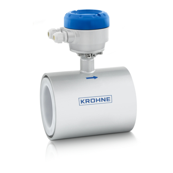
OPTIFLUX 1000
OPTIFLUX 1000
OPTIFLUX 1000
OPTIFLUX 1000
Electromagnetic flow sensor in sandwich design
The documentation is only complete when used in combination with the relevant
documentation for the signal converter.
© KROHNE 01/2013 - 4002298501 - QS OPTIFLUX 1000 R04 en
Quick Start
Quick Start
Quick Start
Quick Start
Advertisement
Table of Contents

Related Manuals for KROHNE OPTIFLUX 1000


Summary of Contents for KROHNE OPTIFLUX 1000
- Page 1 Quick Start Quick Start Quick Start Electromagnetic flow sensor in sandwich design The documentation is only complete when used in combination with the relevant documentation for the signal converter. © KROHNE 01/2013 - 4002298501 - QS OPTIFLUX 1000 R04 en...
-
Page 2: Table Of Contents
3.2 Grounding ........................16 3.3 Virtual reference for IFC 300 (C, W and F version) ............17 3.4 Connection diagrams ..................... 17 4 Technical data 4.1 Dimensions and weights ....................18 www.krohne.com 01/2013 - 4002298501 - QS OPTIFLUX 1000 R04 en... -
Page 3: Safety Instructions
If you need to return the device to the manufacturer or supplier, please fill out the form • contained on the CD-ROM and send it with the device. Unfortunately, the manufacturer cannot repair or inspect the device without the completed form. 01/2013 - 4002298501 - QS OPTIFLUX 1000 R04 en www.krohne.com... -
Page 4: Installation
6 Signal cable (remote versions only) INFORMATION! Assembly materials and tools are not part of the delivery. Use the assembly materials and tools in compliance with the applicable occupational health and safety directives. www.krohne.com 01/2013 - 4002298501 - QS OPTIFLUX 1000 R04 en... -
Page 5: Device Description
3 Compact version with IFC 300 signal converter 4 Compact version with IFC 100 (0°) signal converter 5 Compact version with IFC 100 (45°) signal converter 6 Compact version with IFC 050 (10°) signal converter 01/2013 - 4002298501 - QS OPTIFLUX 1000 R04 en www.krohne.com... -
Page 6: Nameplate
1 Name and address of the manufacturer 2 Type designation of the flowmeter and CE sign with number(s) of notified body / bodies 3 Calibration data 4 PED data www.krohne.com 01/2013 - 4002298501 - QS OPTIFLUX 1000 R04 en... -
Page 7: Storage
• Allen key (4 mm) • Small screwdriver • Wrench for cable glands • Wrench for wall mounting bracket (remote version only) • Torque wrench for installing flowmeter in pipeline 01/2013 - 4002298501 - QS OPTIFLUX 1000 R04 en www.krohne.com... -
Page 8: General Requirements
Do not expose the signal converter to intense vibration. The flowmeters are tested for a • vibration level in accordance with IEC 68-2-64. 2.7.1 Vibration Figure 2-3: Avoid vibrations 2.7.2 Magnetic field Figure 2-4: Avoid magnetic fields www.krohne.com 01/2013 - 4002298501 - QS OPTIFLUX 1000 R04 en... -
Page 9: Installation Conditions
Figure 2-6: 2 and 3 dimensional bends, in front of flowmeter 1 Bends in 2 dimensions: ≥ 5 DN; bends in 3 dimensions: ≥ 10 DN 2.8.3 T-section Figure 2-7: Distance behind a T-section 1 ≥ 10 DN 01/2013 - 4002298501 - QS OPTIFLUX 1000 R04 en www.krohne.com... -
Page 10: Bends
Figure 2-8: Installation in bending pipes Figure 2-9: Installation in bending pipes CAUTION! Avoid draining or partial filling of the flow sensor 2.8.5 Open discharge Figure 2-10: Installation in front of an open discharge www.krohne.com 01/2013 - 4002298501 - QS OPTIFLUX 1000 R04 en... -
Page 11: Flange Deviation
Max. permissible deviation of pipe flange faces: ≤ 0.5 mm / 0.02" Figure 2-11: Flange deviation 2.8.7 Control valve Figure 2-12: Installation in front of a control valve 2.8.8 Pump Figure 2-13: Installation behind a pump 01/2013 - 4002298501 - QS OPTIFLUX 1000 R04 en www.krohne.com... -
Page 12: Air Venting And Vacuum Forces
INSTALLATION OPTIFLUX 1000 2.8.9 Air venting and vacuum forces Figure 2-14: Air venting 1 ≥ 5 m 2 Air ventilation point Figure 2-15: Vacuum 1 ≥ 5 m www.krohne.com 01/2013 - 4002298501 - QS OPTIFLUX 1000 R04 en... -
Page 13: Mounting Position
• Step 1: Apply approx. 50% of max. torque given in table. • Step 2: Apply approx. 80% of max. torque given in table. • Step 3: Apply 100% of max. torque given in table. 01/2013 - 4002298501 - QS OPTIFLUX 1000 R04 en www.krohne.com... - Page 14 Therefore the values should be re- garded as indicative only. CAUTION! Pressures are applicable at 20 C / 68 • ° ° For higher temperatures, the pressure ratings are as per ASME B16.5. • www.krohne.com 01/2013 - 4002298501 - QS OPTIFLUX 1000 R04 en...
-
Page 15: Temperatures
Process [°C] Ambient [°C] Process [°F] Ambient [°F] min. max. min. max. min. max. min. max. Separate flow sensor Compact + IFC 300 Compact + IFC 100 Compact + IFC 050 01/2013 - 4002298501 - QS OPTIFLUX 1000 R04 en www.krohne.com... -
Page 16: Electrical Connections
• Thickness: 3 mm / 0.1" (tantalum: 0.5 mm / 0.02") Note: Note: For diameter DN10 and DN15, grounding rings are integrated as standard in the flow Note: Note: sensor construction. www.krohne.com 01/2013 - 4002298501 - QS OPTIFLUX 1000 R04 en... -
Page 17: Virtual Reference For Ifc 300 (C, W And F Version)
• Electrical conductivity: ≥ 200 µS/cm • Electrode cable: max. 50 m / 164 ft, type DS 3.4 Connection diagrams INFORMATION! For the connection diagrams please refer to the documentation of the applicable signal converter. 01/2013 - 4002298501 - QS OPTIFLUX 1000 R04 en www.krohne.com... -
Page 18: Technical Data
IFC 050 (10 b = 157 mm / 6.18" c = 260 mm / 10.24" Total height = H + a 1 The value may vary depending on the used cable glands. www.krohne.com 01/2013 - 4002298501 - QS OPTIFLUX 1000 R04 en... - Page 19 2.68 5.39 1.85 ½" 1" 2.13 5.79 1½" 3.07 6.38 3.23 2" 3.94 5.94 3.98 3" 5.91 7.08 5.12 12.6 4" 7.87 8.15 6.14 23.1 6" 7.87 10.67 8.62 33.1 01/2013 - 4002298501 - QS OPTIFLUX 1000 R04 en www.krohne.com...
- Page 20 • Measuring systems for the marine industry Head Office KROHNE Messtechnik GmbH Ludwig-Krohne-Str. 5 47058 Duisburg (Germany) Tel.:+49 (0)203 301 0 Fax:+49 (0)203 301 10389 info@krohne.de The current list of all KROHNE contacts and addresses can be found at: www.krohne.com...
Need help?
Do you have a question about the OPTIFLUX 1000 and is the answer not in the manual?
Questions and answers