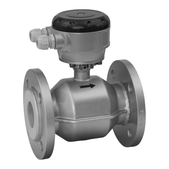
KROHNE Optiflux 2000 Quick Start Manual
Electromagnetic flow sensor
Hide thumbs
Also See for Optiflux 2000:
- Quick start manual (6 pages) ,
- Handbook (48 pages) ,
- Supplementary instructions manual (40 pages)
Table of Contents
Advertisement
Advertisement
Table of Contents

Subscribe to Our Youtube Channel
Related Manuals for KROHNE Optiflux 2000


Summary of Contents for KROHNE Optiflux 2000
- Page 1 OPTIFLUX 2000 OPTIFLUX 2000 Quick Start Quick Start Quick Start Quick Start Electromagnetic flow sensor The documentation is only complete when used in combination with the relevant documentation for the converter. © KROHNE 01/2010 - 7309842200 - QS OPTIFLUX 2000 en...
-
Page 2: Table Of Contents
3.3 Virtual reference for IFC 300 (C, W and F version) ............16 3.4 Connection diagram for measuring sensor, field housing ..........17 4 Technical data 4.1 Dimensions and weight ....................18 www.krohne.com 01/2010 - 7309842200 - QS OPTIFLUX 2000 en... -
Page 3: Safety Instructions
If you need to return the device to the manufacturer or supplier, please fill out the form • contained on the CD-ROM and send it with the device. Unfortunately, the manufacturer cannot repair or inspect the device without the completed form. 01/2010 - 7309842200 - QS OPTIFLUX 2000 en www.krohne.com... -
Page 4: Installation
Check for the correct supply voltage printed on the nameplate. 2.3 Storage • Store the device in a dry and dust-free location. • Avoid lasting direct exposure to the sun. • Store the device in its original packing. www.krohne.com 01/2010 - 7309842200 - QS OPTIFLUX 2000 en... -
Page 5: Transport
Figure 2-2: Transport 2.5 Installation conditions 2.5.1 Inlet and outlet Figure 2-3: Recommended inlet and outlet sections 1 ≥ 5 DN 2 ≥ 2 DN 2.5.2 Mounting position Figure 2-4: Mounting position 01/2010 - 7309842200 - QS OPTIFLUX 2000 en www.krohne.com... -
Page 6: Flange Deviation
Max. permissible deviation of pipe flange faces: ≤ 0.5 mm / 0.02" Figure 2-5: Flange deviation 2.5.4 T-section Figure 2-6: Distance after T-sections 1 ≥ 10 DN 2.5.5 Vibration Figure 2-7: Avoid vibrations www.krohne.com 01/2010 - 7309842200 - QS OPTIFLUX 2000 en... -
Page 7: Magnetic Field
INSTALLATION OPTIFLUX 2000 2.5.6 Magnetic field Figure 2-8: Avoid magnetic fields 2.5.7 Bends Figure 2-9: Installation in bending pipes Figure 2-10: Installation in bending pipes 01/2010 - 7309842200 - QS OPTIFLUX 2000 en www.krohne.com... -
Page 8: Open Discharge
Figure 2-11: Installation before an open discharge 2.5.9 Control valve Figure 2-12: Installation before control valve 2.5.10 Air venting Figure 2-13: Air venting 1 ≥ 5 m 2 Air ventilation point www.krohne.com 01/2010 - 7309842200 - QS OPTIFLUX 2000 en... -
Page 9: Pump
Liner in Polypropylene Liner in Polypropylene Liner in Polypropylene Liner in Polypropylene DN25...150 Liner in Hard rubber Liner in Hard rubber Liner in Hard rubber Liner in Hard rubber DN200...300 DN350...1000 DN1200...3000 01/2010 - 7309842200 - QS OPTIFLUX 2000 en www.krohne.com... -
Page 10: Vacuum Load
Liner in Polypropylene Liner in Polypropylene Liner in Polypropylene 1...6" Liner in Hard rubber Liner in Hard rubber Liner in Hard rubber Liner in Hard rubber 8...12" 14...40" 48...120" 10.9 10.9 www.krohne.com 01/2010 - 7309842200 - QS OPTIFLUX 2000 en... -
Page 11: Mounting
1 Step 1: Apply approx. 50% of max. torque given in table. 2 Step 2: Apply approx. 80% of max. torque given in table. 3 Step 3: Apply 100% of max. torque given in table. 01/2010 - 7309842200 - QS OPTIFLUX 2000 en www.krohne.com... - Page 12 PN 10 20 × M 27 PN 10 20 × M 27 PN 10 24 × M 30 PN 10 28 × M 30 1000 PN 10 28 × M 35 www.krohne.com 01/2010 - 7309842200 - QS OPTIFLUX 2000 en...
- Page 13 16 × 1" 16 × 1 1/8" 20 × 1 1/8" 20 × 1 1/4" 28 × 1 1/4" 28 × 1 1/2" 32 × 1 1/2" 36 × 1 1/2" 01/2010 - 7309842200 - QS OPTIFLUX 2000 en www.krohne.com...
-
Page 14: Electrical Connections
The device must be grounded in accordance with regulations in order to protect personnel against electric shocks. Figure 3-1: Grounding 1 Metal pipelines, not internally coated. Grounding without grounding rings. 2 Metal pipelines with internal coating and non-conductive pipelines. Grounding with grounding rings. www.krohne.com 01/2010 - 7309842200 - QS OPTIFLUX 2000 en... - Page 15 Grounding ring number 3: • 3 mm / 0.1" thick • With cylindrical neck (length 30 mm / 1.25" for DN10...150 / 3/8...6") • Prevents damage to the liner when abrasive liquids are used 01/2010 - 7309842200 - QS OPTIFLUX 2000 en www.krohne.com...
-
Page 16: Virtual Reference For Ifc 300 (C, W And F Version)
3.3 Virtual reference for IFC 300 (C, W and F version) Figure 3-3: Virtual reference Possible if: • ≥ DN10 • Electrical conductivity ≥ 200 µS/cm • Electrode cable max. 50m. www.krohne.com 01/2010 - 7309842200 - QS OPTIFLUX 2000 en... -
Page 17: Connection Diagram For Measuring Sensor, Field Housing
1 Electrical terminal compartment in housing of the signal converter for signal and field current cable. 2 Signal cable A 3 Signal cable B 4 Field current cable C 5 Connection box of measuring sensor 6 Functional ground FE 01/2010 - 7309842200 - QS OPTIFLUX 2000 en www.krohne.com... -
Page 18: Technical Data
Especially for smaller nominal sizes of the sensor, the converter can be bigger than the • sensor. Note that for other pressure ratings than mentioned, the dimensions may be different. • For full information on converter dimensions see relevant documentation. • www.krohne.com 01/2010 - 7309842200 - QS OPTIFLUX 2000 en... - Page 19 1012 1015 1114 1115 1000 1000 1225 1230 1200 1200 1417 1405 1400 1400 1619 1630 1600 1600 1819 1830 1035 1800 1800 2027 2045 1470 2000 2000 2259 2265 1860 01/2010 - 7309842200 - QS OPTIFLUX 2000 en www.krohne.com...
- Page 20 • ° ° For higher temperatures, the pressure and temperature ratings are as per ASME B16.5 (up to • 24") or ASME B16.47 (>24"). Dimensions for other sizes on request. • www.krohne.com 01/2010 - 7309842200 - QS OPTIFLUX 2000 en...
- Page 21 • ° ° For higher temperatures, the pressure and temperature ratings are as per ASME B16.5 (up to • 24") or ASME B16.47 (>24"). Dimensions for other sizes on request. • 01/2010 - 7309842200 - QS OPTIFLUX 2000 en www.krohne.com...
- Page 22 • ° ° For higher temperatures, the pressure and temperature ratings are as per ASME B16.5 (up to • 24") or ASME B16.47 (>24"). Dimensions for other sizes on request. • www.krohne.com 01/2010 - 7309842200 - QS OPTIFLUX 2000 en...
- Page 23 • ° ° For higher temperatures, the pressure and temperature ratings are as per ASME B16.5 (up to • 24") or ASME B16.47 (>24"). Dimensions for other sizes on request. • 01/2010 - 7309842200 - QS OPTIFLUX 2000 en www.krohne.com...
- Page 24 Measuring systems for the oil and gas industry • Measuring systems for sea-going tankers Head Office KROHNE Messtechnik GmbH Ludwig-Krohne-Str. 5 D-47058 Duisburg (Germany) Tel.:+49 (0)203 301 0 Fax:+49 (0)203 301 10389 info@krohne.de The current list of all KROHNE contacts and addresses can be found at: www.krohne.com...
Need help?
Do you have a question about the Optiflux 2000 and is the answer not in the manual?
Questions and answers