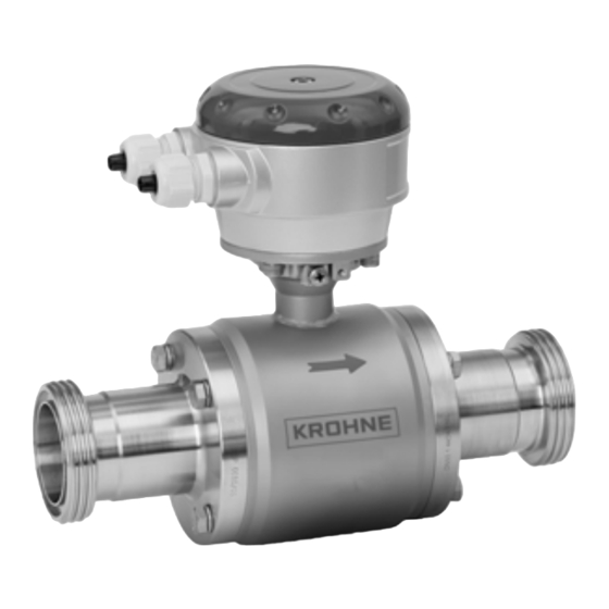
KROHNE OPTIFLUX 6000 Handbook
Electromagnetic flow sensor for hygienic and sanitary applications
Hide thumbs
Also See for OPTIFLUX 6000:
- Handbook (48 pages) ,
- Quick start manual (36 pages) ,
- Supplementary instructions manual (40 pages)
Table of Contents
Advertisement
Quick Links
OPTIFLUX 6000
OPTIFLUX 6000
OPTIFLUX 6000
OPTIFLUX 6000
Electromagnetic flow sensor
for hygienic and sanitary applications
The documentation is only complete when used in combination with the relevant
documentation for the signal converter.
© KROHNE 12/2011 - 4001723701 - HB OPTIFLUX 6000 R01 en
Handbook
Handbook
Handbook
Handbook
Advertisement
Table of Contents

Related Manuals for KROHNE OPTIFLUX 6000


Summary of Contents for KROHNE OPTIFLUX 6000
- Page 1 Handbook Handbook Handbook Handbook Electromagnetic flow sensor for hygienic and sanitary applications The documentation is only complete when used in combination with the relevant documentation for the signal converter. © KROHNE 12/2011 - 4001723701 - HB OPTIFLUX 6000 R01 en...
- Page 2 All rights reserved. It is prohibited to reproduce this documentation, or any part thereof, without the prior written authorisation of KROHNE Messtechnik GmbH. Subject to change without notice. Copyright 2011 by KROHNE Messtechnik GmbH - Ludwig-Krohne-Str. 5 - 47058 Duisburg (Germany) www.krohne.com 12/2011 - 4001723701 - HB OPTIFLUX 6000 R01 en...
-
Page 3: Table Of Contents
3.5.2 Installation of weld-on versions ................... 19 4 Electrical connections 4.1 Safety instructions......................20 4.2 Grounding ........................20 4.3 Virtual reference for IFC 300 (C, W and F version) ............21 4.4 Connection diagrams ..................... 21 12/2011 - 4001723701 - HB OPTIFLUX 6000 R01 en www.krohne.com... - Page 4 5.4.2 Form (for copying) to accompany a returned device............23 5.5 Disposal .......................... 23 6 Technical data 6.1 Technical data......................... 24 6.2 Dimensions and weights ....................28 6.3 Measuring accuracy ....................... 37 7 Notes www.krohne.com 12/2011 - 4001723701 - HB OPTIFLUX 6000 R01 en...
-
Page 5: Safety Instructions
• EMC Directive 2004/108/EC in conjunction with EN 61326-1: 2006 • Low Voltage Directive 2006/95/EC in conjunction with EN 61010-1: 2001 • Pressure Equipment Directive 97/23/EC The manufacturer certifies successful testing of the product by applying the CE marking. 12/2011 - 4001723701 - HB OPTIFLUX 6000 R01 en www.krohne.com... -
Page 6: Safety Instructions From The Manufacturer
The manufacturer reserves the right to alter the content of its documents, including this disclaimer in any way, at any time, for any reason, without prior notification, and will not be liable in any way for possible consequences of such changes. www.krohne.com 12/2011 - 4001723701 - HB OPTIFLUX 6000 R01 en... -
Page 7: Product Liability And Warranty
This document is provided to help you establish operating conditions, which will permit safe and efficient use of this device. Special considerations and precautions are also described in the document, which appear in the form of underneath icons. 12/2011 - 4001723701 - HB OPTIFLUX 6000 R01 en www.krohne.com... -
Page 8: Warnings And Symbols Used
In general, devices from the manufacturer may only be installed, commissioned, operated and maintained by properly trained and authorized personnel. This document is provided to help you establish operating conditions, which will permit safe and efficient use of this device. www.krohne.com 12/2011 - 4001723701 - HB OPTIFLUX 6000 R01 en... -
Page 9: Device Description
Figure 2-1: Scope of delivery 1 Ordered flowmeter 2 Product documentation 3 Factory calibration report 4 CD-ROM with product documentation 5 Grounding rings (optional) 6 Signal cable (remote version only) 12/2011 - 4001723701 - HB OPTIFLUX 6000 R01 en www.krohne.com... -
Page 10: Device Description
Check for the correct supply voltage printed on the nameplate. 1 Name and address of the manufacturer 2 Type designation of the flowmeter and CE sign with number(s) of notified body / bodies 3 Calibration data 4 PED data www.krohne.com 12/2011 - 4001723701 - HB OPTIFLUX 6000 R01 en... -
Page 11: Installation
• Do not lift the device by the signal converter housing. • Do not use lifting chains. • To transport flange devices, use lifting straps. Wrap these around both process connections. Figure 3-1: Transport 12/2011 - 4001723701 - HB OPTIFLUX 6000 R01 en www.krohne.com... -
Page 12: Installation Conditions
OPTIFLUX 6000 3.4 Installation conditions 3.4.1 Inlet and outlet Figure 3-2: Recommended inlet and outlet sections 1 ≥ 5 DN 2 ≥ 2 DN 3.4.2 Mounting position Figure 3-3: Mounting position www.krohne.com 12/2011 - 4001723701 - HB OPTIFLUX 6000 R01 en... -
Page 13: Flange Deviation
Max. permissible deviation of pipe flange faces: ≤ 0.5 mm / 0.02" Figure 3-4: Flange deviation 3.4.4 T-section Figure 3-5: Distance after T-sections 1 ≥ 10 DN 3.4.5 Vibration Figure 3-6: Avoid vibrations 12/2011 - 4001723701 - HB OPTIFLUX 6000 R01 en www.krohne.com... -
Page 14: Magnetic Field
3° 10° 3° 10° 3° 40...50 5° 3° 5° 3° 5° 3° 65...80 10° 3° 10° 3° 10° 3° 5° 3° 5° 3° 5° 3° 125...150 10° 3° 10° 3° www.krohne.com 12/2011 - 4001723701 - HB OPTIFLUX 6000 R01 en... -
Page 15: Bends
INSTALLATION OPTIFLUX 6000 3.4.8 Bends Figure 3-9: Installation in bending pipes Figure 3-10: Installation in bending pipes 3.4.9 Open discharge Figure 3-11: Installation before an open discharge 12/2011 - 4001723701 - HB OPTIFLUX 6000 R01 en www.krohne.com... -
Page 16: Control Valve
3.4.10 Control valve Figure 3-12: Installation before control valve 3.4.11 Air venting Figure 3-13: Air venting 1 ≥ 5 m 2 Air ventilation point 3.4.12 Pump Figure 3-14: Installation after pump www.krohne.com 12/2011 - 4001723701 - HB OPTIFLUX 6000 R01 en... -
Page 17: Temperatures
Clamp joint to ISO 2852 Clamp joint to DIN 32676 Clamp joint to Tri Clamp 1 140°C if ambient temperature ≤ 40°C 2 284°F if ambient temperature ≤ 104°F 3 Without 3A mark 12/2011 - 4001723701 - HB OPTIFLUX 6000 R01 en www.krohne.com... -
Page 18: Mounting
[mm] [Nm] PN 40 4x M6 PN 40 4x M8 PN 25 4x M8 PN 25 6x M8 PN 25 6x M8 PN 10 6x M10 PN 10 6x M10 www.krohne.com 12/2011 - 4001723701 - HB OPTIFLUX 6000 R01 en... -
Page 19: Installation Of Weld-On Versions
• Remove the sensor body and the gaskets from the adapters by loosen the screws. • Weld the adapters completely to the pipe. • When the pipe is cold again, reinstall the gasket and mount the sensor. 12/2011 - 4001723701 - HB OPTIFLUX 6000 R01 en www.krohne.com... -
Page 20: Electrical Connections
The device must be grounded in accordance with regulations in order to protect personnel against electric shocks. Figure 4-1: Grounding options 1. Grounding option without grounding rings 2. Grounding option with grounding rings www.krohne.com 12/2011 - 4001723701 - HB OPTIFLUX 6000 R01 en... -
Page 21: Virtual Reference For Ifc 300 (C, W And F Version)
• Electrical conductivity: ≥ 200 µS/cm • Electrode cable: max. 50 m / 164 ft, type DS 4.4 Connection diagrams INFORMATION! For information regarding electrical connections, please refer tot the documentation of the applicable converter. 12/2011 - 4001723701 - HB OPTIFLUX 6000 R01 en www.krohne.com... -
Page 22: Service22
• such dangerous substances, to enclose a certificate with the device confirming that is safe to handle and stating the • product used. www.krohne.com 12/2011 - 4001723701 - HB OPTIFLUX 6000 R01 en... -
Page 23: Form (For Copying) To Accompany A Returned Device
We hereby confirm that there is no risk to persons or the environment through any residual media contained in the device when it is returned. Date: Signature: Stamp: 5.5 Disposal CAUTION! Disposal must be carried out in accordance with legislation applicable in your country. 12/2011 - 4001723701 - HB OPTIFLUX 6000 R01 en www.krohne.com... -
Page 24: Technical Data
In field (F), wall (W) or rack (R) mount version with IFC 300 converter: OPTIFLUX 6300 F, W or R Nominal diameter DN2.5...150 / 1/10"...6" Measurement range -12...+12 m/s / -40...+40 ft/s www.krohne.com 12/2011 - 4001723701 - HB OPTIFLUX 6000 R01 en... - Page 25 Arrow on flow sensor indicates positive flow direction. ≥ 5 DN Inlet run ≥ 2 DN Outlet run Dimensions and weights Dimensions and weights For detailed information refer to on page 28. 12/2011 - 4001723701 - HB OPTIFLUX 6000 R01 en www.krohne.com...
- Page 26 See documentation of the converter for more information. Type B (BTS) Optional cable, triple shielded. Max. length: 600 m / 1950 ft. (dep. on electrical conductivity and measuring sensor). See documentation of the converter for more information. www.krohne.com 12/2011 - 4001723701 - HB OPTIFLUX 6000 R01 en...
- Page 27 IP 68 field (NEMA 6P) IP 68 factory (NEMA 6P) IP 68 is only available for separate design and with a stainless steel connection box. Hygienic 3A approved EHEDG Conform FDA regulations 12/2011 - 4001723701 - HB OPTIFLUX 6000 R01 en www.krohne.com...
-
Page 28: Dimensions And Weights
DIN 11850 (row 2 or DIN 11866 row A) DN2.5...10 screwed adapter with DN10 process connections / DN15 screwed adapter Nominal size Dimensions [mm] Approx. weight Adapter Flowmeter [kg] 2.5...10 www.krohne.com 12/2011 - 4001723701 - HB OPTIFLUX 6000 R01 en... - Page 29 TECHNICAL DATA OPTIFLUX 6000 DN25...150 bolted adapter Nominal size Dimensions [mm] Approx. weight Adapter Flowmeter [kg] 20.6 132.6 61.3 61.3 41.8 10.9 66.8 11.2 59.3 18.4 66.3 29.5 64.3 44.3 12/2011 - 4001723701 - HB OPTIFLUX 6000 R01 en www.krohne.com...
- Page 30 Rd 65 x 1/6" 91.3 Rd 78 x 1/6" 93.3 Rd 95 x 1/6" 77.8 Rd 110 x 1/4" 107.8 12.5 Rd 130 x 1/4" 109.3 21.8 10 On request www.krohne.com 12/2011 - 4001723701 - HB OPTIFLUX 6000 R01 en...
- Page 31 DIN 11864-2A DIN 11864-2A DIN 11864-2A DN25...150 bolted adapter Nominal size Dimensions [mm] Approx. weight Adapter Flowmeter [kg] 45.8 83.3 83.3 63.8 14.5 122.8 18.6 115.3 28.2 10 On request 12/2011 - 4001723701 - HB OPTIFLUX 6000 R01 en www.krohne.com...
- Page 32 DIN 32676 DIN 32676 DIN 32676 DIN 32676 DN25...100 bolted adapter Nominal size Dimensions [mm] Approx. weight Adapter Flowmeter [kg] 50.5 41.8 50.5 80.8 80.8 67.8 92.8 12.5 85.3 21.8 www.krohne.com 12/2011 - 4001723701 - HB OPTIFLUX 6000 R01 en...
- Page 33 Dimensions [mm] Approx. weights Adapter Flowmeter [kg] 22.6 20.6 132.6 61.3 61.3 63.5 60.3 41.8 76.1 72.9 66.8 10.8 101.6 97.6 59.3 18.4 114.3 110.3 66.3 29.5 139.7 135.7 64.3 44.3 12/2011 - 4001723701 - HB OPTIFLUX 6000 R01 en www.krohne.com...
- Page 34 Approx. weight Adapter Flowmeter [kg] 22.6 50,5 41.8 35.6 50,5 87.8 48.6 87.8 63.5 60.3 77.5 68.3 76.1 72.9 93.3 11.2 101.6 97.6 85.8 19.1 114.3 5 On request 139.7 www.krohne.com 12/2011 - 4001723701 - HB OPTIFLUX 6000 R01 en...
- Page 35 2" 1.85 2.52 3.46 10.75 6.02 4.49 2½" 2.35 3.05 2.69 11.5 7.09 5.55 3" 2.85 3.54 3.68 14.25 7.52 5.98 12.5 4" 3.83 4.68 3.38 14.96 9.53 7.99 21.8 12/2011 - 4001723701 - HB OPTIFLUX 6000 R01 en www.krohne.com...
- Page 36 Adapter Flowmeter [kg] 22.6 Rd 40-6 28.1 147.6 35.5 Rd 60-6 48.6 Rd 70-6 84.3 63.5 60.3 Rd 85-6 69.8 72.9 Rd 98-6 99.8 12.1 97.6 Rd 132-6 21.9 www.krohne.com 12/2011 - 4001723701 - HB OPTIFLUX 6000 R01 en...
-
Page 37: Measuring Accuracy
0.2% of MV + 1 mm/s Compact with IFC 100 Accuracy Curve DN2.5...6 / 1/10...1/4" 0.4% of MV + 1 mm/s as 2 + 0.1% DN10...150 / 3/8...6" 0.3% of MV + 1 mm/s 12/2011 - 4001723701 - HB OPTIFLUX 6000 R01 en www.krohne.com... -
Page 38: Notes
NOTES OPTIFLUX 6000 www.krohne.com 12/2011 - 4001723701 - HB OPTIFLUX 6000 R01 en... - Page 39 NOTES OPTIFLUX 6000 12/2011 - 4001723701 - HB OPTIFLUX 6000 R01 en www.krohne.com...
- Page 40 Measuring systems for the oil and gas industry • Measuring systems for sea-going tankers Head Office KROHNE Messtechnik GmbH Ludwig-Krohne-Str. 5 D-47058 Duisburg (Germany) Tel.:+49 (0)203 301 0 Fax:+49 (0)203 301 10389 info@krohne.de The current list of all KROHNE contacts and addresses can be found at: www.krohne.com...
Need help?
Do you have a question about the OPTIFLUX 6000 and is the answer not in the manual?
Questions and answers