KROHNE OPTIFLUX 6000 Quick Start Manual
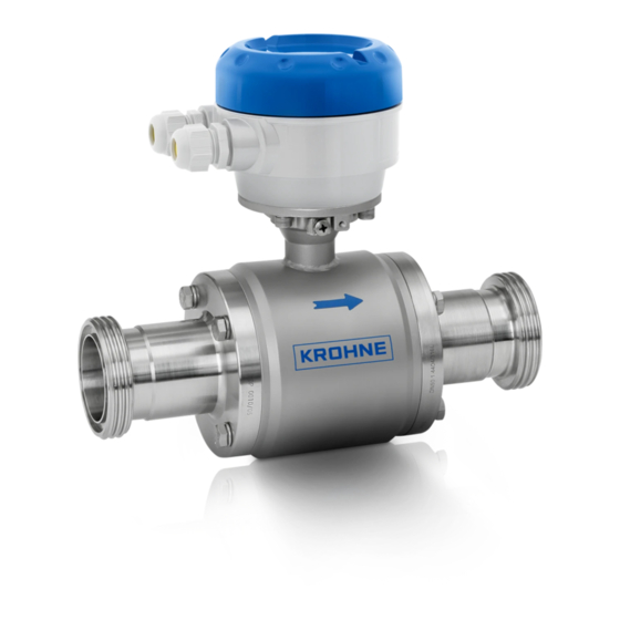
Electromagnetic flow sensor for hygienic and sanitary applications
Hide thumbs
Also See for OPTIFLUX 6000:
- Handbook (48 pages) ,
- Quick start manual (36 pages) ,
- Supplementary instructions manual (40 pages)
Table of Contents
Advertisement
Quick Links
Download this manual
See also:
Handbook
OPTIFLUX 6000
OPTIFLUX 6000
OPTIFLUX 6000
OPTIFLUX 6000
Electromagnetic flow sensor
for hygienic and sanitary applications
The documentation is only complete when used in combination with the relevant
documentation for the signal converter.
© KROHNE 02/2019 - 4002945704 - QS OPTIFLUX 6000 R08 en
Quick Start
Quick Start
Quick Start
Quick Start
Advertisement
Table of Contents

Related Manuals for KROHNE OPTIFLUX 6000


Summary of Contents for KROHNE OPTIFLUX 6000
- Page 1 Quick Start Quick Start Electromagnetic flow sensor for hygienic and sanitary applications The documentation is only complete when used in combination with the relevant documentation for the signal converter. © KROHNE 02/2019 - 4002945704 - QS OPTIFLUX 6000 R08 en...
-
Page 2: Table Of Contents
3.3 Virtual reference for IFC 300 ( C, W and F version) ............19 3.4 Connection diagrams ..................... 19 4 Technical data 4.1 Dimensions and weights ....................20 5 Notes www.krohne.com 02/2019 - 4002945704 - QS OPTIFLUX 6000 R08 en... -
Page 3: Safety Instructions
If you need to return the device to the manufacturer or supplier, please fill out the form • contained on the CD-ROM and send it with the device. Unfortunately, the manufacturer cannot repair or inspect the device without the completed form. 02/2019 - 4002945704 - QS OPTIFLUX 6000 R08 en www.krohne.com... -
Page 4: Installation
4 Signal cable (remote version only) INFORMATION! Assembly materials and tools are not part of the delivery. Use the assembly materials and tools in compliance with the applicable occupational health and safety directives. www.krohne.com 02/2019 - 4002945704 - QS OPTIFLUX 6000 R08 en... -
Page 5: Device Description
Product specific information and extensive product specification is available using PICK, the Product Information Center KROHNE web-tool. PICK can be found via the service menu button on the KROHNE.com website. The following versions are available: • Compact version (the signal converter is installed directly on the measuring sensor) •... -
Page 6: Nameplates (Examples)
6 GK/GKL values (measuring sensor constants), size (mm/inches), field frequency 7 Electronic Revision number 8 Electric values, protection category and materials of wetted parts 9 PED data type I/II/III or SEP www.krohne.com 02/2019 - 4002945704 - QS OPTIFLUX 6000 R08 en... -
Page 7: Storage
• Allen key (4 mm) • Small screwdriver • Wrench for cable glands • Wrench for wall mounting bracket (remote version only) • Torque wrench for installing flowmeter in pipeline 02/2019 - 4002945704 - QS OPTIFLUX 6000 R08 en www.krohne.com... -
Page 8: General Requirements
Do not expose the signal converter to intense vibration. The flowmeters are tested for a • vibration level in accordance with IEC 60068-2-64. 2.7.1 Vibration Figure 2-6: Avoid vibrations 2.7.2 Magnetic field Figure 2-7: Avoid magnetic fields www.krohne.com 02/2019 - 4002945704 - QS OPTIFLUX 6000 R08 en... -
Page 9: Installation Conditions
5 DN; when having bends in 3 dimensions: 10 DN INFORMATION! 2 Dimensional bends occur in a vertical or or or or horizontal plane only, while 3 Dimensional bends occur in both vertical and and horizontal plane. 02/2019 - 4002945704 - QS OPTIFLUX 6000 R08 en www.krohne.com... -
Page 10: T-Section
Figure 2-10: Distance behind a T-section 10 DN 2.8.4 Bends Figure 2-11: Installation in bending pipes ; >2° 1 Drain valve (to empty pipeline) Figure 2-12: Installation in bending pipes www.krohne.com 02/2019 - 4002945704 - QS OPTIFLUX 6000 R08 en... -
Page 11: Open Discharge
1 Drain valve (to empty pipeline) 2.8.6 Control valve Figure 2-14: Installation in front of a control valve ; >2° 1 Drain valve (to empty pipeline) 2.8.7 Pump Figure 2-15: Installation behind a pump 02/2019 - 4002945704 - QS OPTIFLUX 6000 R08 en www.krohne.com... -
Page 12: Air Venting And Vacuum Forces
INSTALLATION OPTIFLUX 6000 2.8.8 Air venting and vacuum forces Figure 2-16: Air venting 2 Air ventilation point Figure 2-17: Vacuum www.krohne.com 02/2019 - 4002945704 - QS OPTIFLUX 6000 R08 en... -
Page 13: Mounting Requirements For Self-Draining
10° 3° 40...50 5° 3° 5° 3° 5° 3° 65...80 10° 3° 10° 3° 10° 3° 5° 3° 5° 3° 5° 3° 125...150 10° 3° 10° 3° 1 on request 02/2019 - 4002945704 - QS OPTIFLUX 6000 R08 en www.krohne.com... -
Page 14: Flange Deviation
Figure 2-19: Flange deviation 2.8.11 Mounting position Figure 2-20: Mounting position • Install flow sensor in line with the pipe axis. • Pipe flange faces must be parallel to each other. www.krohne.com 02/2019 - 4002945704 - QS OPTIFLUX 6000 R08 en... -
Page 15: Mounting
PN 25 4x M8 PN 25 6x M8 PN 25 6x M8 PN 10 6x M10 PN 10 6x M10 INFORMATION! Maximum torque for sizes smaller than DN25: 6 Nm 02/2019 - 4002945704 - QS OPTIFLUX 6000 R08 en www.krohne.com... -
Page 16: Installation Of Weld-On Versions
• Remove the sensor body and the gaskets from the adapters by loosen the screws. • Weld the adapters completely to the pipe. • When the pipe is cold again, reinstall the gasket and mount the sensor. www.krohne.com 02/2019 - 4002945704 - QS OPTIFLUX 6000 R08 en... -
Page 17: Temperatures
Clamp joint to ISO 2852 Clamp joint to DIN 32676 Clamp joint to Tri Clamp 1 140°C if ambient temperature 40°C 2 284°F if ambient temperature 104°F 3 Without 3A mark 02/2019 - 4002945704 - QS OPTIFLUX 6000 R08 en www.krohne.com... -
Page 18: Electrical Connections
Check for the correct supply voltage printed on the nameplate. 3.2 Grounding DANGER! The device must be grounded in accordance with regulations in order to protect personnel against electric shocks. Figure 3-1: Grounding www.krohne.com 02/2019 - 4002945704 - QS OPTIFLUX 6000 R08 en... -
Page 19: Virtual Reference For Ifc 300 ( C, W And F Version)
• Electrical conductivity: 200 μS/cm • Electrode cable: max. 50 m / 164 ft, type DS 3.4 Connection diagrams INFORMATION! For the connection diagrams the documentation of the applicable signal converter. 02/2019 - 4002945704 - QS OPTIFLUX 6000 R08 en www.krohne.com... -
Page 20: Technical Data
DIN 11850 (row 2 or DIN 11866 row A) DN2.5...10 screwed adapter with DN10 process connections / DN15 screwed adapter Nominal size Dimensions [mm] Approx. weight Adapter Flowmeter [kg] 2.5...10 www.krohne.com 02/2019 - 4002945704 - QS OPTIFLUX 6000 R08 en... - Page 21 TECHNICAL DATA OPTIFLUX 6000 DN25...150 bolted adapter Nominal size Dimensions [mm] Approx. weight Adapter Flowmeter [kg] 20.6 132.6 61.3 61.3 41.8 10.9 66.8 11.2 59.3 18.4 66.3 29.5 64.3 44.3 02/2019 - 4002945704 - QS OPTIFLUX 6000 R08 en www.krohne.com...
- Page 22 DN2.5...10 screwed adapter with DN10 process connections / DN15 screwed adapter Nominal size Dimensions [mm] Approx. weight Adapter Flowmeter [kg] 2.5...10 Rd 28 x 1/8" 53.1 Rd 34 x 1/8" 53.1 www.krohne.com 02/2019 - 4002945704 - QS OPTIFLUX 6000 R08 en...
- Page 23 Rd 65 x 1/6" 91.3 Rd 78 x 1/6" 93.3 Rd 95 x 1/6" 77.8 Rd 110 x 1/4" 107.8 12.5 Rd 130 x 1/4" 109.3 21.8 10 On request 02/2019 - 4002945704 - QS OPTIFLUX 6000 R08 en www.krohne.com...
- Page 24 OPTIFLUX 6000 DIN 11864-2A DIN 11864-2A DIN 11864-2A DIN 11864-2A DN25...150 bolted adapter Nominal size Dimensions [mm] Approx. weight Adapter Flowmeter [kg] 45.8 83.3 83.3 63.8 14.5 122.8 18.6 115.3 28.2 www.krohne.com 02/2019 - 4002945704 - QS OPTIFLUX 6000 R08 en...
- Page 25 DIN 32676 DIN 32676 DIN 32676 DIN 32676 DN25...150 bolted adapter Nominal size Dimensions [mm] Approx. weight Adapter Flowmeter [kg] 50.5 41.8 50.5 80.8 80.8 67.8 92.8 12.5 85.3 21.8 02/2019 - 4002945704 - QS OPTIFLUX 6000 R08 en www.krohne.com...
- Page 26 ISO 2037 ISO 2037 ISO 2037 ISO 2037 DN2.5...10 screwed adapter with DN10 process connections / DN17.2 screwed adapter Nominal size Dimensions [mm] Approx. weights Adapter Flowmeter [kg] 2.5...12 17.2 www.krohne.com 02/2019 - 4002945704 - QS OPTIFLUX 6000 R08 en...
- Page 27 Dimensions [mm] Approx. weights Adapter Flowmeter [kg] 22.6 20.6 132.6 61.3 61.3 63.5 60.3 41.8 76.1 72.9 66.8 10.8 101.6 97.6 59.3 18.4 114.3 110.3 66.3 29.5 139.7 135.7 64.3 44.3 02/2019 - 4002945704 - QS OPTIFLUX 6000 R08 en www.krohne.com...
- Page 28 ISO 2852 ISO 2852 DN2.5...10 screwed adapter with DN10 process connections / DN17.2 screwed adapter Nominal size Dimensions [mm] Approx. weight Adapter Flowmeter [Inch] [kg] 2.5...10 1/10"...3/8" 51.6 17.2 1/2" 51.6 www.krohne.com 02/2019 - 4002945704 - QS OPTIFLUX 6000 R08 en...
- Page 29 50,5 41.8 1.5" 35.6 50,5 87.8 2" 48.6 87.8 63.5 2.5" 60.3 77.5 68.3 76.1 3" 72.9 93.3 11.2 101.6 4" 97.6 85.8 19.1 114.3 5" 110.3 139.7 6" 135.7 02/2019 - 4002945704 - QS OPTIFLUX 6000 R08 en www.krohne.com...
- Page 30 Tri Clamp Tri Clamp Tri Clamp DN1/10...1/2" screwed adapter Nominal size Dimensions [inch] Approx. weight Adapter Flowmeter [kg] 1/10"...3/8" 0.37 0.98 1.97 5.59 1.73 1/2" 0.62 0.98 1.97 5.59 1.73 www.krohne.com 02/2019 - 4002945704 - QS OPTIFLUX 6000 R08 en...
- Page 31 3" 2.85 3.54 3.68 13.11 7.52 5.98 12.5 4" 3.83 4.68 3.38 13.11 9.53 7.99 21.8 5" 4.78 5.69 3.54 14.43 10.20 8.62 6" 5.78 6.57 3.62 14.80 11.57 10.00 02/2019 - 4002945704 - QS OPTIFLUX 6000 R08 en www.krohne.com...
- Page 32 DN2.5...10 screwed adapter with DN10 process connections / DN15 screwed adapter Nominal size Dimensions [mm] Approx. weight Adapter Flowmeter [kg] Rd 40-6 Rd 40-6 Rd 40-6 Rd 40-6 Rd 40-6 www.krohne.com 02/2019 - 4002945704 - QS OPTIFLUX 6000 R08 en...
- Page 33 Adapter Flowmeter [kg] 22.6 Rd 40-6 28.1 147.6 35.5 Rd 60-6 48.6 Rd 70-6 84.3 63.5 60.3 Rd 85-6 69.8 72.9 Rd 98-6 99.8 12.1 97.6 Rd 132-6 21.9 02/2019 - 4002945704 - QS OPTIFLUX 6000 R08 en www.krohne.com...
-
Page 34: Notes
NOTES OPTIFLUX 6000 www.krohne.com 02/2019 - 4002945704 - QS OPTIFLUX 6000 R08 en... - Page 35 NOTES OPTIFLUX 6000 02/2019 - 4002945704 - QS OPTIFLUX 6000 R08 en www.krohne.com...
- Page 36 • Process Analysis • Services Head Office KROHNE Messtechnik GmbH Ludwig-Krohne-Str. 5 47058 Duisburg (Germany) Tel.: +49 203 301 0 Fax: +49 203 301 10389 info@krohne.com The current list of all KROHNE contacts and addresses can be found at: www.krohne.com...
Need help?
Do you have a question about the OPTIFLUX 6000 and is the answer not in the manual?
Questions and answers