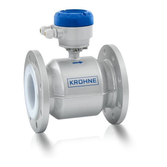
KROHNE OPTIFLUX 2000 Handbook
Electromagnetic flow sensor
Hide thumbs
Also See for OPTIFLUX 2000:
- Quick start manual (6 pages) ,
- Quick start manual (24 pages) ,
- Supplementary instructions manual (40 pages)
Table of Contents
Advertisement
Advertisement
Table of Contents

Related Manuals for KROHNE OPTIFLUX 2000


Summary of Contents for KROHNE OPTIFLUX 2000
- Page 1 OPTIFLUX 2000 OPTIFLUX 2000 OPTIFLUX 2000 Handbook Handbook Handbook Handbook Electromagnetic flow sensor The documentation is only complete when used in combination with the relevant documentation for the signal converter. © KROHNE 4/2014 - 4000839504 - HB OPTIFLUX 2000 R04 en...
- Page 2 All rights reserved. It is prohibited to reproduce this documentation, or any part thereof, without the prior written authorisation of KROHNE Messtechnik GmbH. Subject to change without notice. Copyright 2014 by KROHNE Messtechnik GmbH - Ludwig-Krohne-Str. 5 - 47058 Duisburg (Germany) www.krohne.com 4/2014 - 4000839504 - HB OPTIFLUX 2000 R04 en...
-
Page 3: Table Of Contents
3.6.13 Temperatures ........................21 4 Electrical connections 4.1 Safety instructions......................22 4.2 Grounding ........................22 4.3 Virtual reference for IFC 300 (C, W and F version) ............24 4.4 Connection diagrams ..................... 24 4/2014 - 4000839504 - HB OPTIFLUX 2000 R04 en www.krohne.com... - Page 4 6.3.1 OIML R49 ..........................34 6.3.2 MID Annex MI-001......................... 36 6.4 Measuring accuracy ....................... 39 6.5 Dimensions and weights ....................40 6.6 Pressure derating......................43 6.7 Vacuum load ........................46 7 Notes www.krohne.com 4/2014 - 4000839504 - HB OPTIFLUX 2000 R04 en...
-
Page 5: Safety Instructions
The manufacturer certifies successful testing of the product by applying the CE marking. DANGER! For devices used in hazardous areas, additional safety notes apply; please refer to the Ex documentation. 4/2014 - 4000839504 - HB OPTIFLUX 2000 R04 en www.krohne.com... -
Page 6: Safety Instructions From The Manufacturer
The manufacturer reserves the right to alter the content of its documents, including this disclaimer in any way, at any time, for any reason, without prior notification, and will not be liable in any way for possible consequences of such changes. www.krohne.com 4/2014 - 4000839504 - HB OPTIFLUX 2000 R04 en... -
Page 7: Product Liability And Warranty
This document is provided to help you establish operating conditions, which will permit safe and efficient use of this device. Special considerations and precautions are also described in the document, which appear in the form of underneath icons. 4/2014 - 4000839504 - HB OPTIFLUX 2000 R04 en www.krohne.com... -
Page 8: Warnings And Symbols Used
In general, devices from the manufacturer may only be installed, commissioned, operated and maintained by properly trained and authorized personnel. This document is provided to help you establish operating conditions, which will permit safe and efficient use of this device. www.krohne.com 4/2014 - 4000839504 - HB OPTIFLUX 2000 R04 en... -
Page 9: Device Description
6 Signal cable (remote versions only) INFORMATION! Assembly materials and tools are not part of the delivery. Use the assembly materials and tools in compliance with the applicable occupational health and safety directives. 4/2014 - 4000839504 - HB OPTIFLUX 2000 R04 en www.krohne.com... -
Page 10: Device Description
2 Compact version with IFC 300 signal converter 3 Compact version with IFC 100 (0°) signal converter 4 Compact version with IFC 100 (45°) signal converter 5 Compact version with IFC 050 (10°) signal converter www.krohne.com 4/2014 - 4000839504 - HB OPTIFLUX 2000 R04 en... -
Page 11: Nameplate
Figure 2-3: Example of nameplate 1 Name and address of the manufacturer 2 Type designation of the flowmeter and CE sign with number(s) of notified body / bodies 3 Calibration data 4 PED data 4/2014 - 4000839504 - HB OPTIFLUX 2000 R04 en www.krohne.com... -
Page 12: Installation
• Do not lift the device by the signal converter housing. • Do not use lifting chains. • To transport flange devices, use lifting straps. Wrap these around both process connections. Figure 3-1: Transport www.krohne.com 4/2014 - 4000839504 - HB OPTIFLUX 2000 R04 en... -
Page 13: Pre-Installation Requirements
Do not expose the signal converter to intense vibration. The flowmeters are tested for a • vibration level in accordance with IEC 68-2-64. 3.5.1 Vibration Figure 3-2: Avoid vibrations 3.5.2 Magnetic field Figure 3-3: Avoid magnetic fields 4/2014 - 4000839504 - HB OPTIFLUX 2000 R04 en www.krohne.com... -
Page 14: Installation Conditions
Figure 3-5: 2 and 3 dimensional bends, in front of flowmeter 1 Bends in 2 dimensions: ≥ 5 DN; bends in 3 dimensions: ≥ 10 DN 3.6.3 T-section Figure 3-6: Distance behind a T-section 1 ≥ 10 DN www.krohne.com 4/2014 - 4000839504 - HB OPTIFLUX 2000 R04 en... -
Page 15: Bends
Figure 3-8: Installation in bending pipes CAUTION! Avoid draining or partial filling of the flow sensor 3.6.5 Open feed or discharge Figure 3-9: Installation in front of an open discharge 4/2014 - 4000839504 - HB OPTIFLUX 2000 R04 en www.krohne.com... -
Page 16: Flange Deviation
Max. permissible deviation of pipe flange faces: ≤ 0.5 mm / 0.02" Figure 3-10: Flange deviation 3.6.7 Control valve Figure 3-11: Installation in front of a control valve 3.6.8 Pump Figure 3-12: Installation behind a pump www.krohne.com 4/2014 - 4000839504 - HB OPTIFLUX 2000 R04 en... -
Page 17: Air Venting And Vacuum Forces
INSTALLATION OPTIFLUX 2000 3.6.9 Air venting and vacuum forces Figure 3-13: Air venting 1 ≥ 5 m 2 Air ventilation point Figure 3-14: Vacuum 1 ≥ 5 m 4/2014 - 4000839504 - HB OPTIFLUX 2000 R04 en www.krohne.com... -
Page 18: Mounting Position
• Step 1: Apply approx. 50% of max. torque given in table. • Step 2: Apply approx. 80% of max. torque given in table. • Step 3: Apply 100% of max. torque given in table. www.krohne.com 4/2014 - 4000839504 - HB OPTIFLUX 2000 R04 en... - Page 19 2 DN65 / PN16 is available with standard 8 bolt holes. On request 4 bolt holes is optional. INFORMATION! Other sizes / pressure ratings on request. 4/2014 - 4000839504 - HB OPTIFLUX 2000 R04 en www.krohne.com...
- Page 20 Other sizes / pressure ratings on request. CAUTION! Pressures are applicable at 20 C / 68 • ° ° For higher temperatures, the pressure ratings are as per ASME B16.5. • www.krohne.com 4/2014 - 4000839504 - HB OPTIFLUX 2000 R04 en...
-
Page 21: Temperatures
Polypropylene Separate flow sensor Compact with IFC 300 Compact with IFC 100 Compact with IFC 050 1 Polyolefin is only available for DN200...1000 2 Polypropylene is only available for DN25...150 4/2014 - 4000839504 - HB OPTIFLUX 2000 R04 en www.krohne.com... -
Page 22: Electrical Connections
The device must be grounded in accordance with regulations in order to protect personnel against electric shocks. Figure 4-1: Grounding 1 Metal pipelines, not internally coated. Grounding without grounding rings. 2 Metal pipelines with internal coating and non-conductive pipelines. Grounding with grounding rings. www.krohne.com 4/2014 - 4000839504 - HB OPTIFLUX 2000 R04 en... - Page 23 • 3 mm / 0.1" thick • With cylindrical neck (length 30 mm / 1.25" for DN10...150 / 3/8...6") • Prevents damage to the liner when abrasive liquids are used 4/2014 - 4000839504 - HB OPTIFLUX 2000 R04 en www.krohne.com...
-
Page 24: Virtual Reference For Ifc 300 (C, W And F Version)
• Electrical conductivity: ≥ 200 µS/cm • Electrode cable: max. 50 m / 164 ft, type DS 4.4 Connection diagrams INFORMATION! For the connection diagrams please refer to the documentation of the applicable signal converter. www.krohne.com 4/2014 - 4000839504 - HB OPTIFLUX 2000 R04 en... -
Page 25: Service
• such dangerous substances, to enclose a certificate with the device confirming that is safe to handle and stating the • product used. 4/2014 - 4000839504 - HB OPTIFLUX 2000 R04 en www.krohne.com... -
Page 26: Form (For Copying) To Accompany A Returned Device
We hereby confirm that there is no risk to persons or the environment through any residual media contained in the device when it is returned. Date: Signature: Stamp: 5.4 Disposal CAUTION! Disposal must be carried out in accordance with legislation applicable in your country. www.krohne.com 4/2014 - 4000839504 - HB OPTIFLUX 2000 R04 en... -
Page 27: Technical Data
A signal converter is used to amplify the signal voltage, filter it and convert it into signals for totalising, recording and output processing. Figure 6-1: Measuring principle 1 Induced voltage (proportional to flow velocity) 2 Electrodes 3 Magnetic field 4 Field coils 4/2014 - 4000839504 - HB OPTIFLUX 2000 R04 en www.krohne.com... -
Page 28: Technical Data
In field (F), wall (W) or rack (R) mount version with IFC 300 converter: OPTIFLUX 2300 F, W or R Nominal diameter With IFC 050 converter: DN25...1200 / 1…48" With IFC 100 converter: DN25...1200 / 1…48" With IFC 300 converter: DN25...3000 / 1…120" www.krohne.com 4/2014 - 4000839504 - HB OPTIFLUX 2000 R04 en... - Page 29 Only in combination with the IFC 300 signal converter. Diameter range Class 1:DN65...1600 Class 2: DN25...50 Forward and reverse (bi-directional) flow Liquid temperature range: +0.1°C / 50°C Legal metrology For detailed information refer to on page 34. 4/2014 - 4000839504 - HB OPTIFLUX 2000 R04 en www.krohne.com...
- Page 30 PN16 - 6 bar rated; DN700...2000 PN10 - 6 bar rated; DN700...2000 PN6 - 2 bar rated; DN700...2000 Vacuum load For detailed information refer to Vacuum load on page 46. Pressure loss Negligible www.krohne.com 4/2014 - 4000839504 - HB OPTIFLUX 2000 R04 en...
- Page 31 Option: subsoil coating, offshore coating Connection box Only for remote versions Standard: die-cast aluminium Option: stainless steel Measuring electrodes ® Standard: Hastelloy Option: stainless steel, titanium Other materials on request 4/2014 - 4000839504 - HB OPTIFLUX 2000 R04 en www.krohne.com...
- Page 32 Harmonized standard: EN 61326-1 : 2006 Low voltage directive Directive: 2006/95/EC Harmonized standard: EN 61010 : 2010 Pressure equipment Directive: 97/23/EC directive Category I, II, III or SEP Fluid group 1 Production module H www.krohne.com 4/2014 - 4000839504 - HB OPTIFLUX 2000 R04 en...
- Page 33 IP68 is only available for separate design and with a stainless steel connection box. Shock test IEC 68-2-27 30 g for 18 ms Vibration test IEC 68-2-64 f = 20 - 2000 Hz, rms = 4.5 g, t = 30 min. 4/2014 - 4000839504 - HB OPTIFLUX 2000 R04 en www.krohne.com...
-
Page 34: Legal Metrology
Y [%]: Y [%]: Maximum measuring error Y [%]: Y [%]: 1 ±3% for class 1, ±5% for class 2 devices 2 ±1% for class 1, ±2% for class 2 devices www.krohne.com 4/2014 - 4000839504 - HB OPTIFLUX 2000 R04 en... - Page 35 0.040 0.064 0.0625 0.10 31.3 0.0625 0.10 31.3 0.10 0.16 For DN65 to DN1600; same values (DN, R, Q1, Q2, Q3, Q4) as for OIML R49 class 1 are applicable. 4/2014 - 4000839504 - HB OPTIFLUX 2000 R04 en www.krohne.com...
-
Page 36: Mid Annex Mi-001
Q4 = Q3 * 1.25 Figure 6-3: ISO flow rates added to figure as comparison towards MID X: X: X: X: Flow rate Y [%]: Y [%]: Maximum measuring error Y [%]: Y [%]: www.krohne.com 4/2014 - 4000839504 - HB OPTIFLUX 2000 R04 en... - Page 37 3125 12.8 4000 5000 12.8 4000 5000 12.6 20.2 6300 7875 39.375 6300 7875 10000 12500 10000 12500 16000 20000 1000 16000 20000 1200 16000 20000 1600 312.5 25000 31250 4/2014 - 4000839504 - HB OPTIFLUX 2000 R04 en www.krohne.com...
- Page 38 0.80 0.7875 1.26 1.250 2.00 3.125 7.875 12.6 12.5 20.0 1000 12.5 20.0 1000 12.5 1000 20.0 1600 50.0 4000 10000 10000 16000 1000 16000 1200 16000 1600 312.5 25000 www.krohne.com 4/2014 - 4000839504 - HB OPTIFLUX 2000 R04 en...
-
Page 39: Measuring Accuracy
IFC 100 0.3% of mv + 1 mm/s DN25...1600 / 1...64" IFC 300 0.2% of mv + 1 mm/s DN1800...3000 / > 64" IFC 300 0.3% of mv + 2 mm/s 4/2014 - 4000839504 - HB OPTIFLUX 2000 R04 en www.krohne.com... -
Page 40: Dimensions And Weights
IFC 050 (10°) ) ) ) b = 157 mm / 6.18" c = 260 mm / 10.24" Total height = H + a 1 The value may vary depending on the used cable glands. www.krohne.com 4/2014 - 4000839504 - HB OPTIFLUX 2000 R04 en... - Page 41 1015 1114 1115 1000 1000 1225 1230 1200 1200 1417 1405 1400 1400 1619 1630 1600 1600 1819 1830 1035 1800 1800 2027 2045 1470 2000 2000 2259 2265 1860 4/2014 - 4000839504 - HB OPTIFLUX 2000 R04 en www.krohne.com...
- Page 42 12.50 8" 15.75 15.04 15.00 10" 19.69 17.05 17.50 12" 23.62 20.00 20.50 14" 27.56 21.65 23.00 16" 31.50 23.98 25.50 20" 31.50 28.46 30.50 24" 31.50 33.39 36.00 1345 www.krohne.com 4/2014 - 4000839504 - HB OPTIFLUX 2000 R04 en...
-
Page 43: Pressure Derating
; x = Temperature in [°F] / y = Pressure in [psi] Figure 6-5: Presurre derating; EN 1092-1 1 PN 2.5 2 PN 6 3 PN 10 4 PN 16 5 PN 25 6 PN 40 4/2014 - 4000839504 - HB OPTIFLUX 2000 R04 en www.krohne.com... - Page 44 TECHNICAL DATA OPTIFLUX 2000 Figure 6-6: Presurre derating; ANSI B 16.5 1 300 lbs 2 150 lbs Figure 6-7: Pressure derating; JIS B2220 1 20K 2 10K www.krohne.com 4/2014 - 4000839504 - HB OPTIFLUX 2000 R04 en...
- Page 45 TECHNICAL DATA OPTIFLUX 2000 Figure 6-8: Presurre derating; AWWA C207 1 Class D2 [>12"] 2 Class D1 [4...12"] 3 Class B 4/2014 - 4000839504 - HB OPTIFLUX 2000 R04 en www.krohne.com...
-
Page 46: Vacuum Load
Vacuum load in psia at process temperature of [inches] 68ºF 104ºF 140ºF 176ºF Hard rubber Hard rubber Hard rubber Hard rubber 8...12" 14...40" 48...120" 10.9 10.9 Polypropylene Polypropylene Polypropylene Polypropylene 1...6" Polyolefin Polyolefin Polyolefin Polyolefin 8...40" www.krohne.com 4/2014 - 4000839504 - HB OPTIFLUX 2000 R04 en... -
Page 47: Notes
NOTES OPTIFLUX 2000 4/2014 - 4000839504 - HB OPTIFLUX 2000 R04 en www.krohne.com... - Page 48 Measuring systems for the marine industry Head Office KROHNE Messtechnik GmbH Ludwig-Krohne-Str. 5 47058 Duisburg (Germany) Tel.:+49 203 301 0 Fax:+49 203 301 103 89 info@krohne.com The current list of all KROHNE contacts and addresses can be found at: www.krohne.com...
Need help?
Do you have a question about the OPTIFLUX 2000 and is the answer not in the manual?
Questions and answers