Table of Contents
Advertisement
Quick Links
OPTIFLUX 1000
OPTIFLUX 1000
OPTIFLUX 1000
OPTIFLUX 1000
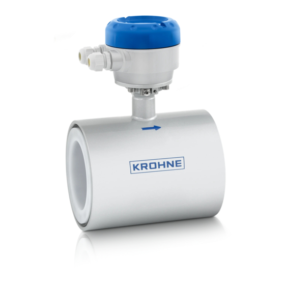
Electromagnetic flow sensor in sandwich version
The documentation is only complete when used in combination with the relevant
documentation for the signal converter.
© KROHNE 10/2011 - 7309832300 - QS OPTIFLUX 1000 R03 en
Quick Start
Quick Start
Quick Start
Quick Start
Advertisement
Table of Contents

Related Manuals for KROHNE OPTIFLUX 1000


Summary of Contents for KROHNE OPTIFLUX 1000
- Page 1 Quick Start Quick Start Quick Start Electromagnetic flow sensor in sandwich version The documentation is only complete when used in combination with the relevant documentation for the signal converter. © KROHNE 10/2011 - 7309832300 - QS OPTIFLUX 1000 R03 en...
-
Page 2: Table Of Contents
3.3 Virtual reference for IFC 300 (C, W and F version) ............14 3.4 Connection diagrams ..................... 14 4 Technical data 4.1 Measuring principle......................15 4.2 Dimensions and weights ....................16 5 Notes www.krohne.com 10/2011 - 7309832300 - QS OPTIFLUX 1000 R03 en... -
Page 3: Safety Instructions
If you need to return the device to the manufacturer or supplier, please fill out the form • contained on the CD-ROM and send it with the device. Unfortunately, the manufacturer cannot repair or inspect the device without the completed form. 10/2011 - 7309832300 - QS OPTIFLUX 1000 R03 en www.krohne.com... -
Page 4: Installation
6 Signal cable (optionally, remote versions only) INFORMATION! Assembly materials and tools are not part of the delivery. Use the assembly materials and tools in compliance with the applicable occupational health and safety directives. www.krohne.com 10/2011 - 7309832300 - QS OPTIFLUX 1000 R03 en... -
Page 5: Device Description
OPTIFLUX 1000 1 Name and address of the manufacturer 2 Type designation of the flowmeter and CE sign with number(s) of notified body / bodies 3 Calibration data 4 PED data 10/2011 - 7309832300 - QS OPTIFLUX 1000 R03 en www.krohne.com... -
Page 6: Storage
• Store the device in a dry and dust-free location. • Avoid lasting direct exposure to the sun. • Store the device in its original packing. • Storage temperature: -50 ...+70°C / -58...+158°F 2.5 Transport Figure 2-2: Transport www.krohne.com 10/2011 - 7309832300 - QS OPTIFLUX 1000 R03 en... -
Page 7: Installation Conditions
OPTIFLUX 1000 2.6 Installation conditions 2.6.1 Inlet and outlet Figure 2-3: Recommended inlet and outlet 1 ≥ 5 DN 2 ≥ 2 DN 2.6.2 Mounting position Figure 2-4: Mounting position 10/2011 - 7309832300 - QS OPTIFLUX 1000 R03 en www.krohne.com... -
Page 8: Flange Deviation
Max. permissible deviation of pipe flange faces: ≤ 0.5 mm / 0.02" Figure 2-5: Flange deviation 2.6.4 T-section Figure 2-6: Distance after T-sections 1 ≥ 10 DN 2.6.5 Vibration Figure 2-7: Avoid vibrations www.krohne.com 10/2011 - 7309832300 - QS OPTIFLUX 1000 R03 en... -
Page 9: Magnetic Field
INSTALLATION OPTIFLUX 1000 2.6.6 Magnetic field Figure 2-8: Avoid magnetic fields 2.6.7 Bends Figure 2-9: Installation in bending pipes Figure 2-10: Installation in bending pipes 10/2011 - 7309832300 - QS OPTIFLUX 1000 R03 en www.krohne.com... -
Page 10: Open Discharge
Figure 2-11: Installation before an open discharge 2.6.9 Control valve Figure 2-12: Installation before control valve 2.6.10 Air venting Figure 2-13: Air venting 1 ≥ 5 m 2 Air ventilation point www.krohne.com 10/2011 - 7309832300 - QS OPTIFLUX 1000 R03 en... -
Page 11: Pump
Temperature range Process [°C] Ambient [°C] Process [°F] Ambient [°F] min. max. min. max. min. max. min. max. Separate flow sensor Compact + IFC 300 C Compact + IFC 100 C 10/2011 - 7309832300 - QS OPTIFLUX 1000 R03 en www.krohne.com... -
Page 12: Torques And Pressures
1 1/2" 1 1/2" 150/300 lb 2" 2" 150/300 lb 3" 3" 150 lb 3" 3" 300 lb 4" 4" 150/300 lb 6" 6" 150 lb 6" 6" 300 lb www.krohne.com 10/2011 - 7309832300 - QS OPTIFLUX 1000 R03 en... -
Page 13: Electrical Connections
2 Metal pipelines with internal coating and non-conductive pipelines. Grounding with grounding rings! Figure 3-2: Grounding ring number 1 Grounding ring number 1 (Optional for DN25...100): • 3 mm / 0.1" thick (tantalum: 0.5 mm / 0.1") 10/2011 - 7309832300 - QS OPTIFLUX 1000 R03 en www.krohne.com... -
Page 14: Virtual Reference For Ifc 300 (C, W And F Version)
• Electrical conductivity ≥ 200 µS/cm • Electrode cable max. 50 m / 164 ft, type DS 3.4 Connection diagrams INFORMATION! For the connection diagrams please refer to the documentation of the applicable converter. www.krohne.com 10/2011 - 7309832300 - QS OPTIFLUX 1000 R03 en... -
Page 15: Technical Data
A signal converter is used to amplify the signal voltage, filter it and convert it into signals for totalising, recording and output processing. 1 Induced voltage (proportional to flow velocity) 2 Electrodes 3 Magnetic field 4 Field coils 10/2011 - 7309832300 - QS OPTIFLUX 1000 R03 en www.krohne.com... -
Page 16: Dimensions And Weights
Especially for smaller nominal sizes of the sensor, the converter can be bigger than the • sensor. Note that for other pressure ratings than mentioned, the dimensions may be different. • For full information on converter dimensions see relevant documentation. • www.krohne.com 10/2011 - 7309832300 - QS OPTIFLUX 1000 R03 en... - Page 17 10.67 8.62 33.1 CAUTION! Pressures are applicable at 20 C / 68 • ° ° For higher temperatures, the pressure ratings are as per ASME B16.5 (up to 24"). • 10/2011 - 7309832300 - QS OPTIFLUX 1000 R03 en www.krohne.com...
-
Page 18: Notes
NOTES OPTIFLUX 1000 www.krohne.com 10/2011 - 7309832300 - QS OPTIFLUX 1000 R03 en... - Page 19 NOTES OPTIFLUX 1000 10/2011 - 7309832300 - QS OPTIFLUX 1000 R03 en www.krohne.com...
- Page 20 Measuring systems for the oil and gas industry • Measuring systems for sea-going tankers Head Office KROHNE Messtechnik GmbH Ludwig-Krohne-Str. 5 D-47058 Duisburg (Germany) Tel.:+49 (0)203 301 0 Fax:+49 (0)203 301 10389 info@krohne.de The current list of all KROHNE contacts and addresses can be found at: www.krohne.com...
Need help?
Do you have a question about the OPTIFLUX 1000 and is the answer not in the manual?
Questions and answers