
Related Manuals for ADLINK Technology ReadySystem 850


Summary of Contents for ADLINK Technology ReadySystem 850
- Page 1 ReadySystem™ 850 1U Computer System with ReadyBoard 850™ Core™2 Duo EPIC SBC User’s Manual Manual Rev.: 2.00 Revision Date: December 15, 2010 Part No: 50-1Z067-1000 Advance Technologies; Automate the World.
-
Page 2: Revision History
Revision History Revision Release Date Description of Change(s) 2.00 2010/12/15 Initial Release... -
Page 3: Preface
RS-850 Preface Copyright 2010 ADLINK Technology Inc. This document contains proprietary information protected by copy- right. All rights are reserved. No part of this manual may be repro- duced by any mechanical, electronic, or other means in any form without prior written permission of the manufacturer. - Page 4 Using this Manual Audience and Scope The ReadySystem™ 850 User’s Manual is intended for hardware technicians and systems operators with knowledge of installing, configuring and operating embedded single board computers. Manual Organization This manual is organized as follows: Preface: Presents copyright notifications, disclaimers, trade- marks, and associated information on the proper usage of this document and its associated product(s).
- Page 5 RS-850 Conventions Take note of the following conventions used throughout this manual to make sure that users perform certain tasks and instructions properly. Additional information, aids, and tips that help users perform tasks. NOTE: NOTE: Information to prevent minor physical injury, component dam- age, data loss, and/or program corruption when trying to com- plete a task.
- Page 6 This page intentionally left blank. Preface...
-
Page 7: Table Of Contents
RS-850 Table of Contents Revision History..............ii Preface ..................iii List of Figures ................ ix List of Tables................xi 1 Introduction ................ 1 Overview................1 Features................1 Specifications............... 2 Mechanical Drawing ............4 2 Getting Started ..............7 Preparation ................7 Installation................ - Page 8 This page intentionally left blank. viii Table of Contents...
-
Page 9: List Of Figures
RS-850 List of Figures Figure 1-1: ReadySystem™ 850 Dimensions ........4 Figure 2-1: ReadySystem™ 850 Front Panel ........8 Figure 2-2: Removing the CF socket cover........9 Figure 2-3: Inserting the CF card ............9 Figure 3-1: Memory socket location ..........13 List of Figures... - Page 10 This page intentionally left blank. List of Figures...
-
Page 11: List Of Tables
RB-850 List of Tables Table 1-1: ReadySystem™ 850 general specifications ....3 Table 3-1: Serial port connector pin definition ........ 14 Table 3-2: VGA connector pin definition ......... 14 Table 3-3: LAN port connector pin definition........15 Table 3-4: USB connector pin definition ......... 15 Table 3-5: PS/2 KB/MS connector pin definition...... - Page 12 This page intentionally left blank. List of Tables...
-
Page 13: Introduction
RS-850 Introduction This chapter will introduce the ReadySystem™ 850, its features, specifications, and mechanical layout. For detailed information on the ReadyBoard™ 850 EPIC SBC, refer the the user manual downloadable from the ADLINK website: http://www.adlinktech.com/PD/web/PD_detail.php?cKind=&pid=942 1.1 Overview The Ampro by ADLINK™ ReadySystem™ 850 is highly compact 1U computer system based on the ReadyBoard™... -
Page 14: Specifications
1.3 Specifications System • Intel® Core™2 Duo P8400, 2.26GHz, 1066MHz FSB, 3MB L2 Cache, 45nm • Intel® Core™2 Duo T7500, 2.20GHz, 800MHz FSB, 4MB L2 Cache, 65nm • Intel® Celeron® T3100, 1.90GHz, 800MHz FSB, 1MB L2 Cache, 45nm • 800/1066 MHz Chipset •... -
Page 15: Table 1-1: Readysystem™ 850 General Specifications
RS-850 Power Requirements Input • 12V DC from AC/DC adapter (75W) Mode • AT power Mechanical and Environment Form Factor • 1U height computer system Dimensions • 220mm x 203mm x 44mm Operating Temp. • Standard: 0°C to 55°C (adapter 40°C only) Storage Temp. -
Page 16: Mechanical Drawing
1.4 Mechanical Drawing Dimensions in mm Figure 1-1: ReadySystem™ 850 Dimensions Introduction... -
Page 17: Getting Started
1. Unpack the contents of the shipping carton. Please check that your package contains the items below. If you discover damaged or missing items, please contact your vendor. ReadySystem 850 AC adapter (12V DC output) 2x power cords (US, EU) Optional items:... -
Page 18: Installation
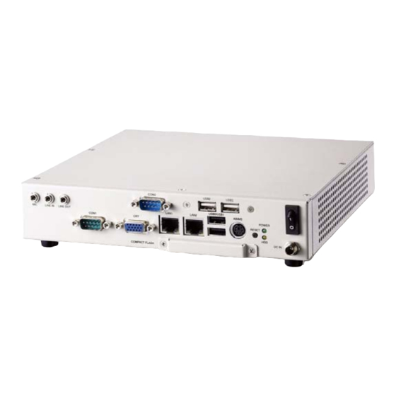
2.2 Installation Connecting Peripherals Connect the desired peripheral devices (e.g. monitor, key- board, mouse, LAN) to the system. Refer to Figure 2-1 below for connector locations. Audio Power LED On/Off Switch DC In KB/MS HDD LED CF Slot Reset Figure 2-1: ReadySystem™ 850 Front Panel The combined PS/2 keyboard/mouse connector requires an optional Y-cable in order to connect both a keyboard and mouse. -
Page 19: Figure 2-2: Removing The Cf Socket Cover
RS-850 Installing a CompactFlash card Before installing or removing a CompactFlash card, make sure the system is powered off and the power supply is discon- nected. To prevent damage to the ReadyBoard or the CompactFlash card, make sure the system is powered off and the power sup- ply is disconnected before installing or removing a Compact- CAUTION: Flash card. -
Page 20: Figure 2-3: Inserting The Cf Card
Insert the CompactFlash card into the socket upside-down, matching the pin-1 orientation of the card as shown. Lip or Catch Edge Pin 1 Keyed Slot Figure 2-3: Inserting the CF card Push the CompactFlash card into the opening until it firmly seats into the socket and mates with the pins. -
Page 21: Powering Up
RS-850 2.3 Powering Up Connect the DC power outlet of the AC adapter to the DC IN socket on the front panel of the ReadySystem. Tighten the screw-lock mechanism of the DC connector to secure it the chassis. Plug the AC socket of the adapter into a suitable wall outlet. Power on any peripheral devices, such as a display monitor. - Page 22 This page intentionally left blank. Getting Started...
-
Page 23: Hardware Information
RS-850 Hardware Information 3.1 Memory Sockets To access the SODIMM memory sockets, remove the 4 screws on the underside of the ReadySystem chassis as shown below. Figure 3-1: Memory socket location Hardware Information... -
Page 24: I/O Connector Pin Definitions
3.2 I/O Connector Pin Definitions COM DB-9 Serial Port Connectors Pin # RS-232 RS-422/485 Table 3-1: Serial port connector pin definition VGA Connector. Signal Name Pin # Pin # Signal Name GREEN GROUND BLUE DDCDAT GROUND HSYNC GROUND VSYNC GROUND DDCCLK GROUND Table 3-2: VGA connector pin definition... -
Page 25: Table 3-3: Lan Port Connector Pin Definition
RS-850 LAN (RJ-45) Ports 10BASE-T/ Pin # 1000BASE-T 100BASE-TX BI_DA+ BI_DA- BI_DB+ BI_DC+ BI_DC- BI_DB- BI_DD+ BI_DD- Table 3-3: LAN port connector pin definition USB Connectors Pin # Signal Name USB- USB+ Table 3-4: USB connector pin definition PS/2 Keyboard/Mouse Connector Pin # Signal Function... - Page 26 This page intentionally left blank. Hardware Information...
-
Page 27: Important Safety Instructions
RS-850 Important Safety Instructions For user safety, please read and follow all instructions, WARNINGS, CAUTIONS, and NOTES marked in this manual and on the associated equipment before handling/operating the equipment. Read these safety instructions carefully. Keep this user’s manual for future reference. Read the specifications section of this manual for detailed information on the operating environment of this equipment. - Page 28 Never attempt to fix the equipment. Equipment should only be serviced by qualified personnel. A Lithium-type battery may be provided for uninterrupted, backup or emergency power. Risk of explosion if battery is replaced with one of an incorrect type. Dispose of used batteries appropriately. WARNING: Equipment must be serviced by authorized technicians when:...
-
Page 29: Getting Service
Address: 5215 Hellyer Avenue, #110, San Jose, CA 95138, USA Tel: +1-408-360-0200 Toll Free: +1-800-966-5200 (USA only) Fax: +1-408-360-0222 Email: info@adlinktech.com ADLINK Technology (China) Co., Ltd. Address: (201203) 300 Fang Chun Rd., Zhangjiang Hi-Tech Park, Pudong New Area, Shanghai, 201203 China Tel: +86-21-5132-8988 Fax:... - Page 30 Address: 84 Genting Lane #07-02A, Cityneon Design Centre, Singapore 349584 Tel: +65-6844-2261 Fax: +65-6844-2263 Email: singapore@adlinktech.com ADLINK Technology Singapore Pte. Ltd. (Indian Liaison Office) Address: No. 1357, "Anupama", Sri Aurobindo Marg, 9th Cross, JP Nagar Phase I, Bangalore - 560078, India Tel: +91-80-65605817 Fax: +91-80-22443548 Email: india@adlinktech.com...
Need help?
Do you have a question about the ReadySystem 850 and is the answer not in the manual?
Questions and answers