Norac UC4+ User & Installation Manual
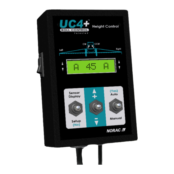
Spray height controller.
commander, navigator
with hardi dah 09 pcb
Hide thumbs
Also See for UC4+:
- Operator's manual (60 pages) ,
- Installation manual (50 pages) ,
- Manual (31 pages)

Related Manuals for Norac UC4+


Summary of Contents for Norac UC4+
- Page 1 Spray Height Controller HARDI AUTOSLANT End User Installation Manual COMMANDER, NAVIGATOR with HARDI DAH 09 PCB...
- Page 2 Reorder P/N: UC4+BC+HD5-INSTE Rev A (HARDI AUTOSLANT) NOTICE: NORAC Systems International Inc. reserves the right to improve products and their specifications without notice and without the requirement to update products sold previously. Every effort has been made to ensure the accuracy of the information contained in this...
-
Page 3: Table Of Contents
Contents Introduction......................1 Parts List........................2 Control Panel Mounting..................2 Cable Installation..................... 3 Calibration........................ 4 UC4+ Menu Structure ..................... 8... -
Page 4: Introduction
1 Introduction Congratulations on your purchase of the NORAC UC4+ Spray Height Controller. This system is manufactured with top quality components and is engineered using the latest technology to provide operating reliability unmatched for years to come. When properly used the system can provide protection from sprayer boom damage, improve sprayer efficiency, and ensure chemicals are applied correctly. -
Page 5: Parts List
2 Parts List Item Part Number Name Quantity 105728 RAM-233 RAIL MOUNT ADAPTER KIT FOR RAM-202 BASE 44658-52 CABLE UC4 BC POWER C10 HARDI 4461BC+HD UC4 PLUS BOOM CONTROL PANEL HARDI 4476BC+MAN7 OPERATOR MANUAL UC4+ SPRAY HEIGHT CONTROL (FIXED BOOM) UC4-BC-HD5-INSTE MANUAL INSTALLATION END-USER HARDI 3 Control Panel Mounting... -
Page 6: Cable Installation
4 Cable Installation Figure 2: Cable Routing Overview 1. Connect C10 to the UC4+ Control Panel in the sprayer cab. Ensure that both plugs (P16A and P4) are connected to the panel. 2. Route the receptacle end (R16) of C10 to the exterior of the cab and connect to C11 at the hitch. -
Page 7: Calibration
5 Calibration Initial Power Up 1. Turn on the power for the UC4+ Control Panel using the switch on the side of its chassis. Ensure that the UC4+ display lights up to confirm that the panel has +12 volt power. 2. - Page 8 Calibrating the Slant Valve The roll (slant) valve can only be calibrated manually as described below. When calibrating the roll valve you must first calibrate the deadzone clockwise and counter clockwise settings and then the gain clockwise and counter clockwise settings. Navigating to the Slant Valve Settings: 1.
- Page 9 Manual Dead Zone Calibration: 1. Follow Section 5.2 Step 1 (level booms, working RPM, etc.) before proceeding. 2. Choose the dead zone up or down setting (Figure 3). 3. Press and hold the "MANUAL" switch. 4. The valve will turn on at the indicated setting for exactly one-second. The screen will show the actual change in height.
- Page 10 Manual Gain Calibration: This test will drive the boom at full speed in the selected direction for one second. Make sure the boom has full range of movement. The purpose of this test is to determine the sprayer boom speeds. It is recommended that you perform each test three times and average your readings.
-
Page 11: Uc4+ Menu Structure
UC4+ Menu Structure Units in Other Roll Main Right Sensor Left Display More ? ROht 46 Tips on RO 30572 LOht 43 LO 30571 Section 5.1 M 45 M Sensi Soil Section 5.2 Retune ? More Setup Main Main On Roll ↑... - Page 12 Canada NORAC Systems International Inc. Phone: (+1) 306 664 6711 Toll Free: 1 800 667 3921 Shipping Address: 3702 Kinnear Place Saskatoon, SK S7P 0A6 United States NORAC, Inc. Phone: (+1) 763 786 3080 Toll Free: 1 866 306 6722...
Need help?
Do you have a question about the UC4+ and is the answer not in the manual?
Questions and answers