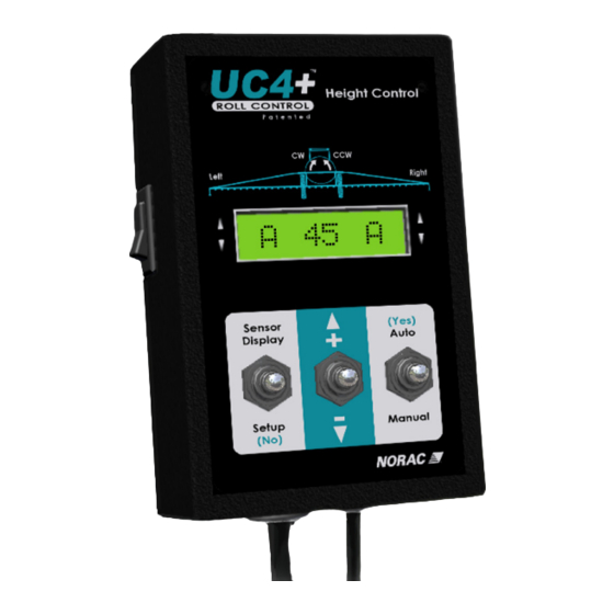
Norac UC4+ Installation Manual
Spray height controller for evrard tr4(r) – auto slant
Hide thumbs
Also See for UC4+:
- Operator's manual (60 pages) ,
- Installation manual (50 pages) ,
- Manual (31 pages)
Summary of Contents for Norac UC4+
- Page 1 Spray Height Controller EVRARD TR4(R) – Auto Slant METEOR AND ALPHA (Blue), REGULOR Electronics Installation Manual Improving the competitiveness of Industry and Agriculture through Precision Measurement...
- Page 2 NOTICE NORAC Systems International Inc. reserves the right to improve products and their specifications without notice and without the requirement to update products sold previously. Every effort has been made to ensure the accuracy of the information contained in this manual. The technical...
-
Page 3: Table Of Contents
TABLE OF CONTENTS INTRODUCTION ..............................1 GENERAL SYSTEM DESCRIPTION ........................2 PARTS LISTS ................................3 UC4+ P ............................3 ARTS INSTALLATION PROCEDURE ........................... 6 ..........................6 UNCTIONALITY CHECK ..........................6 XISTING SYSTEM CHECK ........................7 ING SENSOR INSTALLATION 4.3.1 Bracket assembly ....................................... 7 4.3.2 General Guidelines ...................................... -
Page 4: Introduction
INTRODUCTION Congratulations on your purchase of the NORAC UC4+ Spray Height Controller. This system is manufactured with top quality components and is engineered using the latest technology to provide operating features and reliability unmatched for years to come. When properly used the system can provide protection from sprayer boom damage, improve sprayer efficiency, and ensure chemicals are applied correctly. - Page 5 GENERAL SYSTEM DESCRIPTION Figure 1 depicts the general system layout of the UC4+ Spray Height Control system. Figure 1 – System components and general location (METEOR)
-
Page 6: General System Description
However, NORAC cannot boom movement will need to be done guarantee all parts fit as intended due to the first. Once the hydraulics have been variations of the sprayer by the manufacturer. -
Page 7: Parts Lists
CABLE INTERFACE UC4 BC C14 POWER PIGTAIL 44658-49 CABLE VALVE UC4 BC C5 ROLL PIGTAIL 44782 CONN GP TOWER PLUG 6 WAY 4461BC+ UC4 PLUS BOOM CONTROL PANEL 44631 UC4 ULTRASONIC SENSOR 446BC+MAN7 OPERATOR MANUAL UC4+ SPRAY HEIGHT CONTROL UC4+BC+EV2-INST MANUAL INSTALLATION UC4+ EVRARD TR4(R) - Page 8 3.2 EVRARD P ARTS ISTS The required EVRARD parts necessary for the UC4+ install are listed in Table 2. Table 2 – Recommended EVRARD parts Item Part Number Name Quantity CLAMP ROUND 2IN SS EVRARD07 CABLE TIES...
- Page 9 The parts that come with your UC4+ System are shown below in their general installation configuration. Figure 3 – UC4+ Spray Height Control Components...
-
Page 10: Installation Procedure
INSTALLATION PROCEDURE 4.1 F UNCTIONALITY CHECK Before beginning the install, ensure all hydraulic boom functions are operating properly on the sprayer. o All fold functions o Main lift function o Wing tilt functions o Slant function 4.2 E XISTING SYSTEM CHECK o Inspect boom suspension for loose parts or wear. -
Page 11: Wing Sensor Installation
Control Operator’s Manual (M01) implications. 4. Mount the NORAC UC4+ ultrasonic sensor (E02) into the sensor brackets. The sensors Figure 6 – Breakaway Sensor Mounting should be oriented forward (ahead) of the Bracket Assembly boom (see Figure 7 and Figure 9). -
Page 12: General Guidelines
5. Sensor cables should run through the 4.3.2 General Guidelines mounting bracket tube and then behind the member the bracket is mounted onto. a) In its lowest position, the sensor mouth Cable-tie the connector in place. The cable must be 9 inches or more from the ground. must not be allowed to hang below the boom (Figure 7). -
Page 13: Suggested Mounting For The Wing Bracket For Tr4(R) Boom
4.3.3 Suggested mounting for the wing bracket for TR4(R) boom Use the round pipe clamps to fasten the UC4 sensor bracket to the TR4(R) boom. Mount the sensor on the front-side of the boom, in the position as illustrated in Figure 10 and Figure 11. Ensure the clamps are tight to prevent the bracket from rotating downward. - Page 14 When arranging height sensors, install the serial numbers from lowest to highest, left to right. Apply a light coating of the supplied Permatex Anti-seize grease to all threaded parts upon installation. Figure 12 – Sensor Serial Number Installation Location (example)
-
Page 15: Electrical Installation
4.4 E LECTRICAL NSTALLATION Ensure all cables are routed safely and securely wall (re-use the plug as a grommet by fastened using cable ties. Provide sufficient slack cutting a hole through it). Route the other in the cable where required (between the end of C11 to large grey enclosure at the moving and folding boom parts). - Page 16 Table 3. On cable C13 do not remove the diode pack (the connectors that are held together with a cable tie). Figure 13 – Opened Electronics Enclosure (J1 and J2 as indicated by arrows) NORAC UC4+ EVRARD Function cable...
-
Page 17: Electrical Reference - Cable Drawings
ELECTRICAL REFERENCE – CABLE DRAWINGS 5.1 I C02: 44668 – S ENSOR RANCH ABLE... -
Page 18: Item C10: 44650-35- M Ain Power Cable
5.2 I C10: 44650-35– M AIN POWER CABLE... -
Page 19: Item C11: 44651-03- Valve Extension Cable
5.3 I C11: 44651-03– V ALVE EXTENSION CABLE... -
Page 20: Item C12: 44658 -35 - Pigtail Interface Cable
5.4 I C12: 44658 -35 – P IGTAIL INTERFACE CABLE... -
Page 21: Item C13: 44658 -36 - Wing / Bypass Interface Cable
5.5 I C13: 44658 -36 – W YPASS INTERFACE CABLE... -
Page 22: Item C14: 44658 -28 - P
5.6 I C14: 44658 -28 – P OWER SUPPLY INTERFACE CABLE... -
Page 23: Item C16: 44658-49 - Generic Interface Roll Cable
5.7 I C16: 44658-49 – G ENERIC NTERFACE ABLE www.norac.ca... - Page 24 Canada NORAC Systems International Inc. CALL TOLL FREE: 1-800-667-3921 (306)664-6711 SHIPPING ADDRESS: 3702 Kinnear Place Saskatoon, SK S7P 0A6 United States NORAC, Inc. CALL TOLL FREE: 1-866-306-6722 (952)224-4142 SHIPPING ADDRESS: 6667 West Old Shakopee Road, Suite 111 Bloomington, MN...


Need help?
Do you have a question about the UC4+ and is the answer not in the manual?
Questions and answers