Norac UC4+ Roll Control Installation Manual
Spray height controller
Hide thumbs
Also See for UC4+ Roll Control:
- Installation manual (46 pages) ,
- Installation manual (33 pages)
Table of Contents
Advertisement
Quick Links
Download this manual
See also:
Installation Manual
Advertisement
Table of Contents

Related Manuals for Norac UC4+ Roll Control


Summary of Contents for Norac UC4+ Roll Control
- Page 1 Spray Height Controller CASE IH 4260, 4410 Installation Manual Improving the competitiveness of Industry and Agriculture through Precision Measurement...
- Page 2 Reorder P/N: UC4+BC+CS1-INST REV G (CASE IH 4260, 4410) NORAC Systems International Inc. reserves the right to improve products and their specifications without notice and without the requirement to update products sold previously. Every effort has been made to ensure the accuracy of the information...
-
Page 3: Table Of Contents
TABLE OF CONTENTS INTRODUCTION ..........................1 GENERAL SYSTEM DESCRIPTION ....................2 PARTS LISTS ............................3 INSTALLATION PROCEDURE ......................7 ....................... 7 XISTING SYSTEM CHECK ......................... 7 PEED ....................... 9 ENSOR NSTALLATION ....................12 ENSOR NSTALLATION ....................... 13 ENSOR NSTALLATION 4.5.1 Boom Frame Roll Sensor Mounting ............................ -
Page 4: Introduction
INTRODUCTION Congratulations on your purchase of the NORAC UC4+ Spray Height Controller. This system is manufactured with top quality components and is engineered using the latest technology to provide operating features and reliability unmatched for years to come. When properly used the system can provide protection from sprayer boom damage, improve sprayer efficiency, and ensure chemicals are applied correctly. -
Page 5: General System Description
Any installation specially to fit the sprayer to facilitate a procedure requiring boom movement complete installation. However, NORAC will need to be done first. Once the cannot guarantee all parts fit as intended hydraulics have been disconnected you... -
Page 6: Parts Lists
PARTS LISTS The parts that come with your UC4+ Spray Height Controller System are listed in Table 1. The item number on the left side of this table references each part. Please ensure that all parts in your kit are present before proceeding with your installation. Table 1 –... - Page 7 Table 2 - 44865-04 - Hydraulics Fittings Kit Item Part Number Name Quantity Picture 104369 PLUG - 6MBP 104886 MALE ADAPTER - 8MOR 8MB 104885 TEE ADAPTER - 8FORXR 8MORT 44917 MALE ADAPTER - 6MB-6MOR MACHINED ORB 104590 90 DEG ADAPTER - 6MOR 6FORX90 104586 TEE ADAPTER - 6FORXR 6MORT 103312...
- Page 8 The parts that come with your UC4+ System are shown below in their general installation configuration. Figure 2 – UC4+ Spray Height Controller Components...
- Page 9 Figure 3 – Hydraulic Plumbing Schematic The use of dielectric grease is not recommended on any NORAC electrical connections. To ensure all stainless steel hardware does not gall or seize apply a light coating of the supplied Permatex Anti-seize grease to all threaded parts upon installation. Permatex...
-
Page 10: Installation Procedure
INSTALLATION PROCEDURE 4.1 E 2. Set your sprayer at field working RPM XISTING SYSTEM CHECK on the throttle and mark this value in It is necessary to check the existing Table 4. system’s functionality before installing the UC4+ system. You will need a stopwatch or a watch that displays “seconds”... - Page 11 Table 4 – Boom Test Record (WITHOUT UC4+ System) Working RPM: Trial #1 Trial #2 Trial #3 Avg Time Boom [Sec] [Sec] [Sec] [Sec] Left UP Left DOWN Right UP Right Down Main UP Main DOWN Roll CW Roll CCW Table 5 –...
-
Page 12: Wing Sensor Installation
Sprayer Boom Control Operator’s Manual (M01) for implications. a) Assemble the bolt and nut into the collar. 4. Mount the NORAC UC4+ ultrasonic b) Grease the bottom edge of the sensor (E02) into the sensor brackets. collar and the angled tube of the The sensors should be oriented forward base. - Page 13 General mounting rules for UC4+ When installing UC4+ ultrasonic wing sensors: sensors (E02), start with the smallest serial number on the a) In its lowest position, the sensor mouth left hand side proceeding to the must be 9 inches or more from the largest serial number on the ground.
- Page 14 Apply a light coating of the supplied Permatex Anti-seize grease to all threaded parts upon installation. 3 SENSOR SYSTEM 5 SENSOR SYSTEM Figure 9 – Sensor Serial Number Installation Location...
-
Page 15: Main Lift Sensor Installation
4.4 M ENSOR NSTALLATION 1. Assemble the main lift sensor bracket Mount the sensor onto the sensor (B11) as shown in Figure 10. mounting collar (Figure 11). Sensor Mounting Collar Bracket Tube Bracket Base Sensor Mounting Tab Figure 10 – Main Lift Sensor Bracket 2. -
Page 16: Roll Sensor Installation
4.5 R ENSOR NSTALLATION Mount the roll sensors to the included When mounting the roll sensors, use the roll sensor brackets using the machine following guidelines and refer to Figure 14. screws nylon lock nuts, a) The smaller the distance between A and illustrated in Figure 13. -
Page 17: Boom Frame Roll Sensor Mounting
4.5.1 Boom Frame Roll Sensor Mounting 1. Use the supplied hardware to mount the boom frame roll sensor (E04) as shown in Figure 15. When mounting the boom frame roll sensor follow these guidelines: a) To prevent bending the bracket, ensure bolts are placed as close together as possible (minimize C in Figure 15). -
Page 18: Chassis Roll Sensor Mounting
4.5.2 Chassis Roll Sensor Mounting 1. It is often best to cable tie the chassis 3. Cable-tie the temperature probe cable roll sensor in place. When mounting and AMP (circular) connector securely the chassis roll sensor follow the to a frame member. guidelines and refer to Figure 16. -
Page 19: Hydraulic Installation
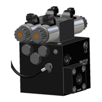
4.6.1 Valve Assembly 1. On a clean surface remove all plastic plugs from the NORAC hydraulic Valve (V01) (Figure 18). 2. Install the 6MB-6MJ (F08) fittings on the “P” and “T” ports and tighten to 18 ft- lbs. -
Page 20: Valve Mounting
4.6.2 Valve Mounting 1. Mount the NORAC valve (V01) on the sprayer using valve mounting bracket (B10). 2. As shown in Figure 20, screw short side of the threaded rods into the bottom of the valve block at least 3/8". -
Page 21: Hydraulic Plumbing
“B” ports of the NORAC valve block. 6. Tee the pressure (H06) and tank (H06) lines for the NORAC block in to the existing lines from the existing valve block, using the “T” fittings (F04) and... -
Page 22: Electrical Installation
4.7 E LECTRICAL NSTALLATION 1. Install the UC4+ Control Panel (E01) in the cab of the sprayer. Mount the panel where it will be clearly visible and within easy reach of the operator. A good spot to mount the UC4+ control panel is on the right hand side of the cab to the Roll Over Protection Bar. - Page 23 Figure 23 – Cable Configurations: C10 and C11 2. Connect the UC4+ power cable (C10) to the UC4+ Control Panel in the sprayer cab. Ensure that both plugs are connected to the panel. 3. Connect the 3-pin AMP connector (P3) auxiliary power connection in the sprayer cab.
- Page 24 7. Connect the 6-pin shroud (S6) on C12, to the mating connector (T6A) on 14. Install the 2-pin connectors from C03 C11. onto each NORAC valve as shown in Figure 25. 8. Route the free end of C12 to the existing left and right boom control 15.
-
Page 25: Completing The Installation
FOLDING boom movement. 4. Repeat the Boom Speed Test as described in Section 4.2 Boom Speed Test with the NORAC UC4+ System installed. Record the results for comparison in Table 5. 5. The procedure for the installation of the UC4+ System is now complete. -
Page 26: Electrical Reference - Cable Drawings
ELECTRICAL REFERENCE – CABLE DRAWINGS 5.1 I C02: 44668 – S ENSOR RANCH ABLE 5.2 I C02B: 44664 – C UC4 CAN N ABLE... -
Page 27: Item C03: 44656D - Cable Valve Variable Rate Dt
5.3 I C03: 44656D – C ABLE ALVE ARIABLE... -
Page 28: Item C10: 44650-39 - Power Cable Generic Self -Propelled
5.4 I C10: 44650-39 – P OWER ABLE ENERIC ROPELLED... -
Page 29: Item C11: 44651-03 - Extension Cable Valve Generic
5.5 I C11: 44651-03 – E XTENSION ABLE ALVE ENERIC... -
Page 30: Tem C12: 44658-21 - Interface Able Uc4 Bc C12 Gp Main
5.6 I C12: 44658-21 – I UC4 BC C12 GP M NTERFACE ABLE... -
Page 31: Item C18: 44658-40 - Interface Cable Uc4 Bc C18 Gp Main Extension
5.7 I C18: 44658-40 – I UC4 BC C18 GP M NTERFACE ABLE XTENSION... - Page 32 Canada NORAC Systems International Inc. CALL TOLL FREE: 1-800-667-3921 (306)664-6711 SHIPPING ADDRESS: 3702 Kinnear Place Saskatoon, SK S7P 0A6 United States NORAC, Inc. CALL TOLL FREE: 1-866-306-6722 (952)224-4142 SHIPPING ADDRESS: 6667 West Old Shakopee Road, Suite 111 Bloomington, MN...
Need help?
Do you have a question about the UC4+ Roll Control and is the answer not in the manual?
Questions and answers