Norac uc4+ Installation Manual
Spray height controller rau oem (fixed geometry- ra2)
Hide thumbs
Also See for uc4+:
- Operator's manual (60 pages) ,
- Installation manual (50 pages) ,
- Manual (31 pages)

Related Manuals for Norac uc4+


Summary of Contents for Norac uc4+
- Page 1 Spray Height Controller RAU OEM (Fixed Geometry- RA2) Installation Manual Improving the competitiveness of Industry and Agriculture through Precision Measurement...
- Page 2 Reorder P/N: UC4+BC+RA2-INST Rev F (RAU FIXED GEOMETRY OEM) NOTICE NORAC Systems International Inc. reserves the right to improve products and their specifications without notice and without the requirement to update products sold previously. Every effort has been made to ensure the accuracy of the information contained...
-
Page 3: Table Of Contents
TABLE OF CONTENTS INTRODUCTION..........................2 GENERAL SYSTEM DESCRIPTION ....................3 PARTS LISTS..........................4 UC4+ P ........................4 ARTS INSTALLATION PROCEDURE....................... 6 ......................6 UNCTIONALITY HECK ......................6 XISTING SYSTEM CHECK ..................... 8 ING SENSOR INSTALLATION 4.3.1 General mounting rules for UC4+ ultrasonic wing sensors:..........10 4.3.2 Suggested mounting location for wing bracket on HSA boom .......... -
Page 4: Introduction
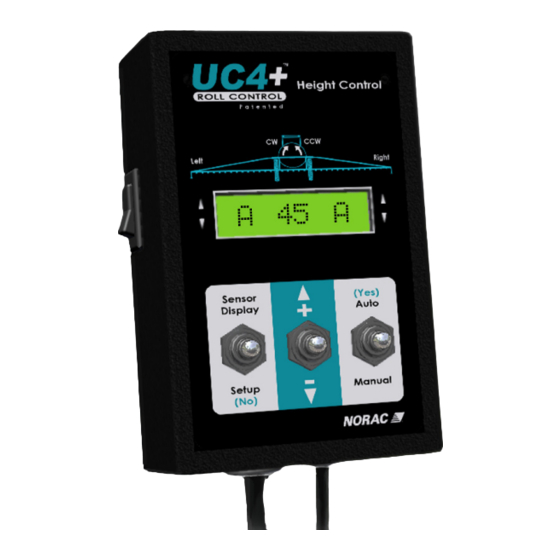
INTRODUCTION Congratulations on your purchase of the NORAC UC4+ Spray Height Controller. This system is manufactured with top quality components and is engineered using the latest technology to provide operating features and reliability unmatched for years to come. When properly used the system can provide protection from sprayer boom damage, improve sprayer efficiency, and ensure chemicals are applied correctly. -
Page 5: General System Description
All parts supplied are selected specially to fit the sprayer to facilitate a complete installation. However, NORAC cannot guarantee all parts fit as intended due to the variations of the sprayer by the manufacturer. Please read this manual in its entirety before attempting installation. -
Page 6: Parts Lists
446BC+MAN6-1 MANUAL UC4+ BOOM CONTROL 2008 OPERATORS SMALL BOOKLET M01B* 446BC+MAN6-2 MANUAL UC4+ BOOM CONTROL 2008 QUICK REFERENCE SMALL BOOKLET UC4+BC+RA2-INST MANUAL INSTALLATION UC4+ RAU FIXED GEOMETRY M13* UC4+BC+RA1-INSTE MANUAL INSTALLATION END-USER RAU OEM Items numbers followed with an asterisks are to be delivered to the sprayer End-User. - Page 7 The parts that come with your UC4+ System are shown below in their general installation configuration. Figure 2 – UC4+ Spray Height Control Components...
-
Page 8: Installation Procedure
INSTALLATION PROCEDURE 4.1 F UNCTIONALITY HECK Before beginning the install, ensure all manual hydraulic boom functions are operating properly on the sprayer. o All fold functions o Main lift function o Wing tilt functions (if applicable) o Slant function 4.2 E XISTING SYSTEM CHECK o Ensure the boom suspension is configured as a short-pendulum (insert boom pin to constrain the long-pendulum suspension) - Page 9 o Adjust the slant speed of the boom until the full stroke (from full counter-clockwise to full clockwise) is 6 seconds (Figure 4). This is the time required for the slant cylinder to travel from fully extended to fully retracted, or vice-versa. 6 seconds Figure 4: Setting the slant speed...
-
Page 10: Wing Sensor Installation
4.3 W ING SENSOR INSTALLATION 1. Assemble the breakaway sensor mounting Brackets (B11) as show in Figure 5. Figure 5 – Breakaway sensor assembly To assemble the breakaway sensor bracket: a) Assemble the bolt and nut into the collar. b) Grease the bottom edge of the collar and the angled tube of the base. c) Place the collar onto the angled tube of the mounting base. - Page 11 3. The sensor mounting brackets can be installed with the mounting base in front of or behind the mounting tube (the difference in mounting can be seen in Figure 7 and Figure 8). When installing the UC4+ sensors (E02), start with the smallest serial number on the left hand side proceeding to the largest serial number on the right hand side (Figure 13).
-
Page 12: General Mounting Rules For Uc4+ Ultrasonic Wing Sensors
4.3.1 General mounting rules for UC4+ ultrasonic wing sensors: a) In its lowest position, the sensor mouth must be 9 inches or more from the ground. b) The bottom of the sensor must be at least 9 inches in front of the spray nozzles. c) The bottom of the sensor must be at least 9 inches above the spray nozzles. -
Page 13: Suggested Mounting Location For Wing Bracket On Hsa Boom
4.3.2 Suggested mounting location for wing bracket on HSA boom Mounting the NORAC UC4 breakaway bracket to the HSA aluminum boom will require the use of a Rau aluminum boom clamp, as illustrated below. Rau clamp Figure 9: UC4 Sensor Bracket mounted to boom using Rau HSA boom clamp Using this clamp will also require adjusting the hole width of the NORAC bracket to accommodate the larger bolts and differences in dimensions between the 2 parts. -
Page 14: Suggested Mounting Location For Wing Bracket On Hss Boom
Use the square bracket mounting plate and the included hardware to mount the UC4 bracket to the HSS boom, as illustrated. NORAC hardware Figure 11: HSS Boom Mount the UC4 bracket to the HSS boom as shown below, inside of the break-away section. - Page 15 NOTE: When arranging height sensors, install the serial numbers from lowest to highest, left to right. Figure 13 – Sensor serial number installation location (example)
-
Page 16: Electrical Installation
4.4.1 Rau valve connections 1. Refer to Figure 14. 2. Connect the Rau Valve Drive PCB (C12) to the NORAC harness (Item C11) using harness C13. Connect all 3 Weatherpack connectors. 3. Plug item C12 into C14, and securely fasten the module to the sprayer with cable-ties. - Page 17 c. Connect the wires to the Rau drivers (via the screw terminals) as listed below. Tee the wires in together with the exiting wiring for all boom function connections. Rau CONNECTION C14 WIRE +12V BLACK +12V BLUE DIRECTION 1 (BLUE DIR. WIRE) WHITE DIRECTION 2 (YLW/GRN DIR.
-
Page 18: Completing The Factory Installation
4.5 C OMPLETING THE FACTORY INSTALLATION 1. Test the functionality of the original manufacturer’s boom controls. The NORAC Control Panel (E01) does not need to be powered up for the original switches to function. Unfold the booms and raise/lower each boom and main section. Confirm that the cabling/hoses are agreeable to the entire range of motion. - Page 19 IMPORTANT: Ensure the “ROLL KP” values are set to a value of 50 for both roll directions. Depending on the software version, this value may require manual adjustment (using the +/- toggle switch from the ROLL KP screens. Refer to Figure 16 for details on navigating to the ROLL KP screens.
-
Page 20: Electrical Reference - Cable Drawings
ELECTRICAL REFERENCE – CABLE DRAWINGS C02: 44668 – S ENSOR RANCH ABLE... -
Page 21: Item C10: 44650-35- Cable Power Generic Pull -Type
5.2 I C10: 44650-35- C ABLE OWER ENERIC... -
Page 22: Item C11: 44651-03- Cable Extension Valve Generic
5.3 I C11: 44651-03- C ABLE XTENSION ALVE ENERIC... -
Page 23: Item C13: 44658-58- Interface Cable Uc4 Rau I/O 1
5.4 I C13: 44658-58- I UC4 R I/O 1 NTERFACE ABLE... -
Page 24: Item C14: 44658-59- Interface Cable Uc4 Rau I/O 2
5.5 I C14: 44658-59- I UC4 R I/O 2 NTERFACE ABLE... - Page 25 Canada NORAC Systems International Inc. CALL TOLL FREE: 1-800-667-3921 (306)664-6711 SHIPPING ADDRESS: 3702 Kinnear Place Saskatoon, SK S7P 0A6 United States Norac, Inc. CALL TOLL FREE: 1-866-306-6722 (763)786-3080 SHIPPING ADDRESS: 1290 Osborne Rd NE, Suite F Fridley, MN 55432-2892...
Need help?
Do you have a question about the uc4+ and is the answer not in the manual?
Questions and answers