Table of Contents
Advertisement
Quick Links
OWNER'S MANUAL
Inversion Table
5201.4-022616
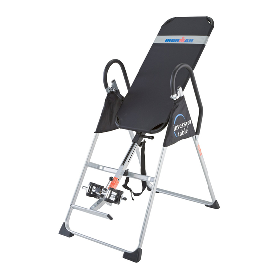
The specifications of this product may vary from this photo and are subject to change without notice.
IRONMAN, IRONMAN TRIATHLON and M-DOT are registered trademarks of World Triathlon Corporation.
This product is licensed by the World Triathlon Corporation.
Advertisement
Table of Contents

Related Manuals for Ironman Fitness 5201


Summary of Contents for Ironman Fitness 5201
- Page 1 OWNER’S MANUAL Inversion Table 5201.4-022616 The specifications of this product may vary from this photo and are subject to change without notice. IRONMAN, IRONMAN TRIATHLON and M-DOT are registered trademarks of World Triathlon Corporation. This product is licensed by the World Triathlon Corporation.
-
Page 3: Table Of Contents
TABLE OF CONTENTS SERVICE ---------------------------------------------------------------------------------------------2 IMPORTANT SAFETY INSTRUCTIONS -----------------------------------------------------3 LABEL PLACEMENT------------------------------------------------------------------------------5 OVERVIEW DRAWING ---------------------------------------------------------------------------6 HARDWARE &TOOLS LIST ---------------------------------------------------------------------7 PARTS LIST -----------------------------------------------------------------------------------------8 ASSEMBLY -------------------------------------------------------------------------------------------9 OPERATION AND ADJUSTMENTS -----------------------------------------------------------18 STORAGE --------------------------------------------------------------------------------------------22 WARM UP --------------------------------------------------------------------------------------------23 WARRANTY -----------------------------------------------------------------------------------------24 PART REQUEST FORM --------------------------------------------------------------------------25... -
Page 4: Service
SERVICE IMPORTANT: FOR NORTH AMERICA ONLY For damaged, defective products, questions, replacement parts, or any other service support, please contact our customer service department (8:00 AM - 5:00 PM Pacific Standard Time, Daily) by the below methods: For Best Service, please Email: Service@paradigmhw.com Response Time: 1-2 Business Days Website:... -
Page 5: Important Safety Instructions
IMPORTANT SAFETY INSTRUCTIONS ... - Page 6 IMPORTANT SAFETY INSTRUCTIONS Read all instructions carefully before assembling operating this product. Retain this owner’s manual and keep the original purchase receipt for future reference. 1. Consult your physician or other health care professionals before using the inversion table. 2. Always wear proper exercise apparel when using the equipment. 3.
-
Page 7: Label Placement
LABEL PLACEMENT... -
Page 8: Overview Drawing
OVERVIEW DRAWING... -
Page 9: Hardware &Tools List
HARDWARE & TOOLS LIST (15) Lock Nut M8 (11) Hex Head Bolt M6x47 (13) Washer Ø 20 x Ø 8.5 x 1.5 6PCS 2PCS 12PCS (16) Lock Nut M6 (38) Hex Head Bolt M8x23 (27) Washer Ø 16 x Ø 6.5 x 1.0 2PCS 2PCS 4PCS... -
Page 10: Parts List
PARTS LIST Part# Description Q’ty Part# Description Q’ty Upper Bed Frame Bushing Front U-Frame Rear U-Frame Handlebar Adjustable Boom Knob Bed Frame Rubber Heel Holder Pivot Arm Nylon Strap Adjustable lnstep Frame Loop Strap Steel Heel Holder Bracket Strap Lock Folding Arm Nylon Bed Foam Grip... -
Page 11: Assembly
ASSEMBLY Tool: Phillips Screwdriver 1PC Step 1 Stand up the base by separating the u-frames. Pull the Front and Rear U-Frames (1,2) as far apart from each other as possible. Then push down on the middle of the two Folding Arms (8) until they are fully locked down. - Page 12 ASSEMBLY Step 2 Attach two Nut Caps (53) onto Lock Nuts (15). Slide one Protective Cover (37) on to each side of the base as shown, and pull down on the Protective Covers (37) until the bottom of the covers are slightly lower than the Folding Arms (8).
- Page 13 ASSEMBLY Step 3 Slide the bottom of the Pivot Arms (5) into the backrest that located at the each side of the Bed Frame (4), align to the desired hold on the arm with the peg on the bracket. Insert the peg into the hold to lock the Pivot Arm (5) in place. It is recommended that you use the bottom hold on the Pivot Arms (5) until you become more familiar with equipment.
- Page 14 ASSEMBLY Tool: Wrench 2PCS Step 5 Slide the Rod (9) through the large round hold on the side of Adjustable Boom (3), and secure the Rod (9) on the Adjustable Boom (3) with a Hex Head Bolt (11), Lock Nut (16), and two Washers (27).
- Page 15 ASSEMBLY Tool: Wrench 2PCS Step 6 Slide the Foot Bar (39) into the bottom of the Adjustable Boom (3) and align two of the holes on the Foot Bar (39) with two holes on the boom. Secure the Foot Bar (39) in place using two Hex Head Bolts (40), Lock Nut (15), and four Washers (13).
- Page 16 ASSEMBLY Tool: Wrench 2PCS Step 7 Remove the Square End Cap (41) on the back of square bracket of Adjustable Boom (3). Attach the Adjustable Instep Frame (6) to the Adjustable Boom (3) by inserting the Adjustable Instep Frame (6) into the square bracket on the boom. Slide the Adjustable Instep Frame (6) completely into the square bracket, insert the Hex Head Bolt (11) with a Washer (27) halfway through the square bracket, slide the Hex Head Bolt (11) through the ring at the bottom of the Spring (23), slide the Hex Head Bolt (11)
- Page 17 ASSEMBLY Step 8 Pull out the Large Spring Knob (18), and slide the Adjustable Boom (3) into the square bracket on the bottom of the Bed Frame (4) as shown. Slide the Adjustable Boom (3) upward until the desired height on the Height Scale (44) is just below the bracket on the bed frame. Lock the Adjustable Boom (3) in place by releasing the Large Spring Knob (18) and sliding the Adjustable Boom (3) up or down slightly down until the Large Spring Knob (18) “pops”...
- Page 18 ASSEMBLY Tool: Wrench 2PCS Step 9 Attach the top end of Handlebar (29) onto the Rear U-Frame (2) and Pivot Arm Reinforcement Plate (54) with one Hex Head Bolt (38), Lock Nut (15), and two Washers (13). Attach the bottom end of the Handlebar (29) onto the Rear U-Frame (2) with one Hex Head Bolt (43), Lock Nut (15), and two Washers (13).
- Page 19 ASSEMBLY Step 10 Attach the Nylon Strap (32) to the Strap Lock (34) by inserting the end of the Nylon Strap (32) up through the bottom of the Strap Lock (34), loop the Nylon Strap (32) over the pre-assembled Loop Strap (33) and down through the Strap Lock (34). Now, loop the strap back over itself and insert back through the Strap Lock (34), and pull tight to secure.
-
Page 20: Operation And Adjustments
OPERATION AND ADJUSTMENTS The Pivot Arms (5) can be adjusted to allow for a greater or lesser degree of inversion. To adjust the Pivot Arms (5) simply pull out on them until the post is out of the hole, slide them up or down to the desired hole, push in until the post goes through the desired hole, The bottom hole provides the least amount of inversion, while the top hole provides the greatest amount, It is recommended that beginners use the bottom hole until they are familiar with the inversion... - Page 21 OPERATION AND ADJUSTMENTS BALACING THE INVERSION TABLE The inversion table is like a very sensitively balanced fulcrum. It responds to very slight changes in weight distribution. So, it is very important to make sure that the height is adjusted properly. To do this, mount the inversion table, lock your ankles into the heel holders, and lie back with your hands at your sides.
- Page 22 OPERATION AND ADJUSTMENTS SUGGESTIONS FOR USE 1. Begin slowly: invert only 15~20 degrees to begin with. Stay inverted only as long as you are comfortable. Return upright slowly. 2. Make gradual changes: increase the angle only if it is comfortable. Increase angle only a few degrees at a time. Increase the time of use 1~2 minutes up to ten over a period of weeks.
- Page 23 OPERATION AND ADJUSTMENTS STRAP ADJUSTMENT For added safety, a nylon strap has been included to restrict the degree of inversion. This strap can be adjusted to different lengths to allow for a greater or lesser degree of inversion. To lengthen the Nylon Strap (32) feed the top end of Nylon Strap (32) into the strap lock, and pull on the lower end of the strap.
-
Page 24: Storage
STORAGE For your storage convenience, the inversion table can be folded down to place against a wall, under a bed, or in a storage area. -
Page 25: Warm
WARM UP Quadriceps Stretch With one hand against a wall for balance, reach behind you and pull your right foot up. Bring your heel as close to your buttocks as possible. Hold for 15 counts and repeat with left foot up. Inner Thigh Stretch Sit with the soles of your feet together with your knees pointing outward. -
Page 26: Warranty
WARRANTY MANUFACTURER’S LIMITED WARRANTY Paradigm Health & Wellness warrants to the original purchaser that this product is free from defects in material and workmanship when used for the purpose intended, under the conditions that it has been installed and operated in accordance with Paradigm’s Owner’s Manual. -
Page 27: Part Request Form
PART REQUEST FORM Paradigm Health & Wellness, Inc. EMAIL THIS FORM WITH YOUR RECIEPT OF PURCHASE TO Service@paradigmhw.com NAME: _______________________________________________________ ADDRESS: ____________________________________________________ CITY ______________ STATE ______________ ZIP ___________________ TELEPHONE: (Day) _____________________________________________ (Night) ____________________________________________ SERIAL#: _____________________________________________________ MODEL#: _____________________________________________________ PURCHASE DATE: ______________________________________________ PLACE OF PURCHASE: _________________________________________ PART # DESCRIPTION “YOUR ORDER WILL BE PROCESSED WITHIN 3 BUSINESS DAYS”...
Need help?
Do you have a question about the 5201 and is the answer not in the manual?
Questions and answers