Table of Contents
Advertisement
OWNER'S MANUAL
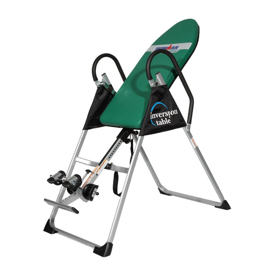
GRAVITY 2000
AB TRAINING INVERSION SYSTEM
Item#5208
The specifications of this product may vary from this photo and are subject to change without notice.
IRONMAN, IRONMAN TRIATHLON and M-DOT are registered trademarks of World Triathlon Corporation.
This product is licensed by the World Triathlon Corporation.
Advertisement
Table of Contents

Related Manuals for Ironman Fitness GRAVITY 2000


Summary of Contents for Ironman Fitness GRAVITY 2000
- Page 1 GRAVITY 2000 AB TRAINING INVERSION SYSTEM Item#5208 The specifications of this product may vary from this photo and are subject to change without notice.
- Page 2 5208.2‐072915 ...
-
Page 3: Table Of Contents
TABLE OF CONTENTS SERVICE-------------------------------------------------------------------- 2 IMPORTANT SAFETY INSTRUCTIONS--------------------------- 3 LABELPLACEMENT----------------------------------------------------- 5 OVERVIEW DRAWING------------------------------------------------- 6 PART LIST----------------------------------------------------------------- 8 HARDWARE LIST & TOOLS----------------------------------------- 10 ASSEMBLY----------------------------------------------------------------11 HOW TO USE-------------------------------------------------------------18 OPERATION AND ADJUSTMENTS-------------------------------- 20 STORAGE----------------------------------------------------------------- 22 WARM UP----------------------------------------------------------------- 23 WARRANTY-------------------------------------------------------------- 24 FAX FORM---------------------------------------------------------------- 25 1 ... -
Page 4: Service
SERVICE IMPORTANT: FOR NORTH AMERICA ONLY To request product service and order replacement parts, please call our customer service department at: 1-844-641-7922 Daily, 8:00 AM-5:00 PM Pacific Standard Time, service@paradigmhw.com or email us at: Please visit our website at www.paradigmhw.com. Please have the following information ready when requesting for service: Your name Phone number... -
Page 5: Important Safety Instructions
IMPORTANT SAFETY INSTRUCTIONS This inversion table was designed and built for optimum safety. However, certain precautions apply whenever you operate the exercise equipment. Be sure to read the entire manual before assembling and operating this equipment. When using an appliance, basic precautions should always be followed, including the following: ... - Page 6 IMPORTANT SAFETY INSTRUCTIONS WARNING - Risk of personal injury - Keep body parts, hair, loose clothing and jewelry clear of all moving parts. NOTE: Maximum user weight for this product is 300 lbs (136 kgs.) Maximum Rated Height for this product is 6’6”/198cm. ...
-
Page 7: Labelplacement
LABEL PLACEMENT 5 ... -
Page 8: Overview Drawing
OVERVIEW DRAWING 6 ... -
Page 9: Part List
PART LIST Description Q'ty Description Q'ty Front U-Frame Handlebar Rear U-Frame Knob Adjustable Boom Rubber Heel Holder Bed Frame Nylon Strap Pivot Arm Loop Strap Adjustable lnstep Frame Strap Lock Heel Holder Bracket Foam Bed Folding Arm Foam Grip Protective Cover Bolt M8x23 Hex Head Bolt M8x23 Hex Head Bolt M6x47... -
Page 10: Hardware List & Tools
HARDWARE LIST & TOOLS (11) Hex Head Bolt M6x47 (13) Washer Ø20xØ8.5x1.5 (15) Lock Nut M8 2 PCS 12 PCS 6 PCS (38) Hex Head Bolt M8x23 (16) Lock Nut M6 (27) Washer Ø16xØ6.5x1.0 2 PCS 2 PCS 4 PCS (40) Hex Head Bolt (43) Hex Head Bolt (48) Screw M6x20 M8x50... -
Page 11: Assembly
ASSEMBLY The product weighs more than 44lbs / 20kgs and should be assembled and moved by two or more people. Hardware: Tool: (51) Screw M6x25 4 PCS Phillips Screwdriver 1 PC (53) Washer Ø13xØ6.5x1.0 8 PCS (48) Screw M6x20 4 PCS Step 1. - Page 12 ASSEMBLY Hardware: (54) Nut Cap Ø27xØ13.5 2 PCS Step 2. Install two Ø27xØ13.5 Nut Caps (54) onto M8 Lock Nuts (15). Slide the Protective Covers (37) on to each side of the base as shown, and pull down on the covers until the bottom of the covers are slightly lower than the Folding Arms (8).
- Page 13 ASSEMBLY Step 3. Slide the bottom of the Pivot Arms (5) into the brackets, located at each side of the Bed Frame (4), align to the desired hole on the arm with the peg on the bracket. Insert the peg into the hole to lock the pivot arm in place.
- Page 14 ASSEMBLY Step 5. Attach the top end of Handlebar (29) onto the Rear U-Frame (2) and Pivot Arm Reinforcement Plate (55) with one M8x23 Hex Head Bolt (38), M8 Lock Nut (15), and two Ø20xØ8.5x1.5 Washers (13). Attach the bottom end of the Handlebar (29) onto the Rear U-Frame (2) with one M8x38 Hex Head Bolt (43), M8 Lock Nut (15), and two Ø20xØ8.5x1.5 Washers (13).
- Page 15 ASSEMBLY Step. 6 Pull out the Ball Spring Knob (18), and slide the Adjustable Boom (3) into the square bracket on the bottom of the Bed Frame (4) as shown. Slide the boom upward, until the desired height on the Height Scale (44) is just below the bracket on the bed frame. Lock the Adjustable Boom (3) in place by releasing the Ball Spring Knob (18) and sliding the Adjustable Boom (3) up or down slightly until the spring knob "pops"...
- Page 16 ASSEMBLY Step. 7 Slide the Rod (9) through the large round hole on the side of Adjustable Boom (3), and secure the Rod (9) on the Adjustable Boom (3) with a M6x47 Hex Head Bolt (11), M6 Lock Nut (16), and two Ø16xØ6.5x1.0 Washers (27).
- Page 17 ASSEMBLY Step. 8 Slide the Foot Bar (39) into the bottom of the Adjustable Boom (3) and align two of the holes on the Foot Bar (39) with the two holes on the Adjustable Boom (3). Secure the Foot Bar (39) in place using two M8x50 Hex Head Bolts (40), M8 Lock Nuts (15), and four Ø20xØ8.5x1.5 Washers (13).
-
Page 18: Front U-Frame 1
ASSEMBLY Step.10 Attach the Nylon Strap (32) to the Strap Lock (34) by inserting the end of the strap up through the bottom of the strap lock, loop the Nylon Strap (32) over the Pre-assembled Loop Strap (33) and down through the Strap Lock (34). - Page 19 SAFETY OEPRATING INSTRUCTIONS Incorrect Correct Pivot arm is NOT aligned correctly. Make sure the pivot arm is inserted The pivot arm is not inserted all all the way into the slot. Pivot arm is the way into the curved slot. aligned correctly when the groove sits directly on the curved slot and the pivot arm is able to rotate freely.
-
Page 20: Adjustable Boom 1
SAFETY OEPRATING INSTRUCTIONS SHORTEN LENGTHEN THE STRAP For added safety, a nylon strap has been included to restrict the degree of inversion. This strap can be adjusted to different lengths to allow for a greater or lesser degree of inversion. To lengthen the Nylon Strap (32) feed the top end of Nylon Strap (32) into the strap lock, and pull on the lower end of the strap. -
Page 21: Operation And Adjustments
OPERATION AND ADJUSTMENTS PIVOT ARMS The Pivot Arms (5) can be adjusted to allow for a greater or lesser degree of inversion. To adjust the Pivot Arms (5) simply pull out on them until the post is out of the hole, slide them up or down to the desired hole, push in until the post goes through the desired hole. - Page 22 OPERATION AND ADJUSTMENTS GENERAL PRECAUTIONS 1. Make sure that the Pivot Arms (5) are locks on the lowest hole for the first few attempts. 2. It is recommended that someone be with you while you are using this inversion table for the first few times.
- Page 23 PERATION N AND ADJ JUSTMEN TS BALAN NCING T THE INVE ERSION T TABLE he inversion n table is li ike a very sensitively y balanced fulcrum. It respond ds to very s slight anges in w weight distr ribution. S So, it is ve ery importa nt to make e sure that...
- Page 24 OPERATION AND ADJUSTMENTS SUGGESTIONS FOR USE 1. Begin slowly: invert only 15~20 degrees to begin with. Stay inverted only as long as you are comfortable. Return upright slowly. 2. Make gradual changes: increase the angle only if it is comfortable. Increase angle only a few degrees at a time.
-
Page 25: Storage
STORAGE&MAINTENANCE FOLDING THE INVERSION TABLE For your storage convenience, the inversion table can be folded down to place against a wall, under a bed, or in a storage area. To fold the inversion table pull out the Ball Spring Knob (18) and loosen Knob (30). -
Page 26: Warm Up
WARM U adriceps S Stretch With h one hand d against a a wall for b balance, re ach behind u and pull y your right fo oot up. B Bring your h heel as clo ... -
Page 27: Warranty
WARRANTY MANUFACTURER’S LIMITED WARRANTY Paradigm Health & Wellness warrants to the original purchaser that this product is free from defects in material and workmanship when used for the purpose intended, under the conditions that it has been installed and operated in accordance with Paradigm’s Owner’s Manual. -
Page 28: Fax Form
FAX FORM Paradigm Health & Wellness, Inc. PARTS REQUEST FAX FORM Please fax this form to (1-626-810-2166) OR YOU CAN EMAIL CUSTOMER SERVICE REQUESTS TO service@paradigmhw.com NAME: _______________________________________________________ ADDRESS: ____________________________________________________ CITY ______________ STATE ______________ ZIP ___________________ TELEPHONE: (Day) _____________________________________________ (Night) ____________________________________________ (Email Address) ____________________________________ SERIAL#: __________________________________________ MODEL#: __________________________________________...
Need help?
Do you have a question about the GRAVITY 2000 and is the answer not in the manual?
Questions and answers
Can I purchase a new T type spring knob for my ironman gravity 2000 inversion table. Part # 017 in the online manual.