Table of Contents
Advertisement
Quick Links
OWNER'S MANUAL
Inversion Table
Item#5800
5800.5‐120216
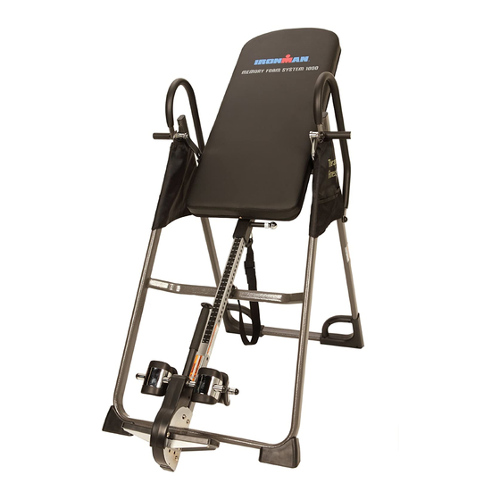
The specifications of this product may vary from this photo and are subject to change without notice.
IRONMAN, IRONMAN TRIATHLON and M-DOT are registered trademarks of World Triathlon Corporation.
This product is licensed by the World Triathlon Corporation.
Advertisement
Table of Contents

Related Manuals for Ironman Fitness 5800


Summary of Contents for Ironman Fitness 5800
- Page 1 OWNER’S MANUAL Inversion Table Item#5800 5800.5‐120216 The specifications of this product may vary from this photo and are subject to change without notice. IRONMAN, IRONMAN TRIATHLON and M-DOT are registered trademarks of World Triathlon Corporation. This product is licensed by the World Triathlon Corporation.
- Page 2 STOP ARRÊT ALTO PLEASE DO NOT RETURN THIS PRODUCT TO THE STORE. If you need help with product information, assembly, or replacement parts. Please contact customer service. Email us at: Service@paradigmhw.com Or call us at: 1-844-641-7922 Hours: 8:00 am to 5:00 pm (PST) Daily ...
-
Page 3: Table Of Contents
TABLE OF CONTENTS SERVICE ------------------------------------------------------------------------- 2 LABEL PLACEMENT --------------------------------------------------------- 3 IMPORTANT SAFETY GUIDELINES ------------------------------------- 4 OVERVIEW DRAWING ------------------------------------------------------ 6 PARTS LIST --------------------------------------------------------------------- 7 HARDWARE & TOOLS PACK ---------------------------------------------- 9 ASSEMBLY ---------------------------------------------------------------------- 10 SAFETY OPERATING INSTRUCTIONS --------------------------------- 16 OPERATION AND ADJUSTMENTS --------------------------------------- 17 STORAGE &... -
Page 4: Service
SERVICE IMPORTANT: FOR NORTH AMERICA ONLY For damaged or defective product, questions, replacement parts or any other service support, please contact our customer service department (8:00 AM - 5:00 PM Pacific Standard Time, Daily) by the below methods: For Best Service, please Email: Service@paradigmhw.com Response Time: 1-2 Business Days Website:... -
Page 5: Label Placement
LABEL PLACEMENT... -
Page 6: Important Safety Guidelines
IMPORTANT SAFETY GUIDELINES Read all instructions before using the Inversion Table. When using an Inversion table, basic precautions should always be followed, including the following: WARNING - To reduce the risk of injury to persons: Make sure your equipment is correctly assembled before you use it. Be sure all screws, nuts, and bolts are tightened prior to use. - Page 7 IMPORTANT SAFETY GUIDELINES Warning - To Reduce The Risk Of Personal Injury - Read And Understand All Read The Instructions Before Using The Inversion Table. Do not use this equipment if you have any of the following conditions or ailments: Pregnancy ...
-
Page 8: Overview Drawing
OVERVIEW DRAWING... -
Page 9: Parts List
PARTS LIST Description Description Front U-Frame 28 Upper Bed Frame Bushing Rear U-Frame 29 Handlebar Adjustable Boom 30 Knob Bed Frame 31 Rubber Heel Holder Pivot Arm 32 Nylon Strap Adjustable Lock Plate 33 Loop Strap Steel Heel Holder Bracket 34 Strap Lock Folding Arm 35 Foam Bed... - Page 10 PARTS LIST Description Description 55 Nut Cap Ø27xØ13.5 67 Screw ST4.2x12 56 Adjustable Handle 68 Screw ST4.8x20 57 Handle Cap 69 Shaft Nut Ø8 58 Handle Spring 70 Bolt M5x10 59 Button 71 Bolt M8x50 60 Handle Tip 72 Pivot Arm Ring 73 Rear Left Foot Cap with HandleⅠ...
-
Page 11: Hardware & Tools Pack
HARDWARE & TOOLS PACK... -
Page 12: Assembly
ASSEMBLY Tool: Multi Hex Tool with Phillips Screwdriver Step 1: Stand up the base of the machine by separating the Front and Rear U-Frames (1, 2). Pull the Front and Rear U-Frames (1, 2) apart from each other. Push down on the middle of the Folding Arms (8) until they are fully locked down. - Page 13 ASSEMBLY (55) Nut Cap 2 PCS Step 2: Install a Nut Cap (55) onto the Lock Nuts (15). Slide a Protective Cover (37) on to each side of the base as shown. Pull down on the Protective Covers (37) until the bottom of the covers are slightly lower than the Folding Arms (8). Use the Velcro straps on the bottom of the Protective Covers (37) to secure the covers to the Folding Arms (8).
- Page 14 ASSEMBLY Step 4: Mount the Bed Frame (4) to the Rear U-Frame (2) by inserting the ends of the Pivot Arms (5) into the channels on the plates. The slotted portion of the rollers on the end of the Pivot Arms (5) should be inserted into the channels on the plates.
- Page 15 ASSEMBLY Step 6: Pull out the Large Spring Knob (18) and slide the Adjustable Boom (3) into the square bracket on the bottom of the Bed Frame (4) as shown. Slide the Adjustable Boom (3) to the desired height. Lock the Adjustable Boom (3) in place by releasing the Large Spring Knob (18) and sliding the Adjustable Boom (3) up or down slightly until the Large Spring Knob (18) "pops"...
- Page 16 ASSEMBLY Tool: 13 15 Multi Hex Tool with Phillips Screwdriver Hex Wrench Step 7: Attach the top end of the Handlebar (29) onto the Rear U-Frame (2) and Pivot Arm Ring (72) with one Hex Head Bolt (38), one Lock Nut (15), and two Washers (13).
- Page 17 ASSEMBLY Step 8: Attach the Nylon Strap (32) to the Strap Lock (34) by inserting the end of Nylon Strap (32) up through the bottom of the Strap Lock (34), loop the Nylon Strap (32) over the Pre-assembled Loop Strap (33) and down through the Strap Lock (34).
-
Page 18: Safety Operating Instructions
SAFETY OPERATING INSTRUCTIONS Incorrect Correct The slot of the Pivot arm is NOT aligned Make sure the pivot arm is inserted all correctly. The pivot arm must be inserted the way into the slot. When the Pivot all the way into the curved slot. arm is aligned correctly in the groove of the curved slot the pivot arm will be able to move freely. -
Page 19: Operation And Adjustments
OPERATION AND ADJUSTMENTS SHORTEN LENGTHEN THE STRAP A nylon strap has been included to restrict the degree of inversion. This strap can be adjusted to different lengths to allow for a greater or lesser degree of inversion. To lengthen the Nylon Strap (32) feed the top end of Nylon Strap (32) into the strap lock, and pull on the lower end of the strap. - Page 20 OPERATION AND ADJUSTMENTS PIVOT ARMS The Pivot Arms (5) can be adjusted to allow for a greater or lesser degree of inversion. To adjust the Pivot Arms (5) simply pull out on them until the post is out of the hole, slide them up or down to the desired holes. The bottom hole provides the least amount of inversion, while the top hole provides the greatest amount.
- Page 21 OPERATION AND ADJUSTMENTS USING THE INVERSION TABLE Start by lying fully back on the bed with your hands at your side, or resting on your thighs. See Fig. 1 Keeping your hands close to your body, begin to raise your arms slowly allowing the table to rotate backward.
-
Page 22: Storage & Troubleshooting Section
STORAGE & TROUBLESHOOTING SECTION For your convenience, the inversion table can be folded down to place against a wall, under a bed, or in a storage area. Any other servicing not described in this manual should be performed ONLY by an authorized service representative. In case the Adjustable Handle (56) is too tight to release Rubber Heel Holder (31), Follow these steps:... -
Page 23: Warranty
WARRANTY MANUFACTURER’S LIMITED WARRANTY Paradigm Health & Wellness warrants to the original purchaser that this product is free from defects in material and workmanship when used for the purpose intended, under the conditions that it has been installed and operated in accordance with Paradigm’s Owner’s Manual. -
Page 24: Part Request Form
PARTS REQUEST FORM Paradigm Health & Wellness, Inc. EMAIL THIS FORM WITH YOUR RECIEPT OF PURCHASE TO Service@paradigmhw.com NAME: _______________________________________________________ ADDRESS: ____________________________________________________ CITY ______________ STATE ______________ ZIP ___________________ TELEPHONE: (Day) _____________________________________________ (Night) ____________________________________________ SERIAL#: _____________________________________________________ MODEL#: _____________________________________________________ PURCHASE DATE: ______________________________________________ PLACE OF PURCHASE: _________________________________________ PART # DESCRIPTION “YOUR ORDER WILL BE PROCESSED WITHIN 3 BUSINESS DAYS”...
Need help?
Do you have a question about the 5800 and is the answer not in the manual?
Questions and answers