Table of Contents
Advertisement
Quick Links
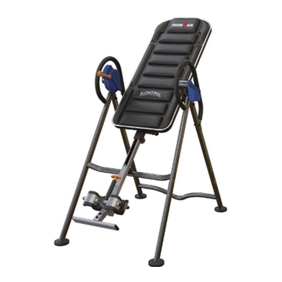
OWNER'S MANUAL
iControl Disk Brake
Inversion Table
Item#5610
The specifications of this product may vary from this photo and are subject to change without notice.
IRONMAN, IRONMAN TRIATHLON and M-DOT are registered trademarks of World Triathlon Corporation.
This product is licensed by the World Triathlon Corporation.
Advertisement
Table of Contents

Related Manuals for Ironman Fitness iControl 500


Summary of Contents for Ironman Fitness iControl 500
- Page 1 OWNER’S MANUAL iControl Disk Brake Inversion Table ...
- Page 2 5610.2‐050515 ...
-
Page 3: Table Of Contents
TABLE OF CONTENTS SERVICE-------------------------------------------------------------------- 2 IMPORTANT SAFETY INSTRUCTIONS--------------------------- 3 LABELPLACEMENT----------------------------------------------------- 5 OVERVIEW DRAWING------------------------------------------------- 6 PART LIST----------------------------------------------------------------- 8 HARDWARE LIST & TOOLS----------------------------------------- 10 ASSEMBLY----------------------------------------------------------------11 HOW TO USE-------------------------------------------------------------18 OPERATION AND ADJUSTMENTS-------------------------------- 20 STORAGE----------------------------------------------------------------- 22 WARM UP----------------------------------------------------------------- 23 WARRANTY-------------------------------------------------------------- 24 FAX FORM---------------------------------------------------------------- 25 1 ... -
Page 4: Service
SERVICE IMPORTANT: FOR NORTH AMERICA ONLY To request product service and order replacement parts, please call our customer service department at: 1-844-641-7922 Daily 8:00 AM-5:00 PM Pacific Standard Time, service@paradigmhw.com or email us at: Please visit our website at www.paradigmhw.com. Please have the following information ready when requesting for service: Your name Phone number... -
Page 5: Important Safety Instructions
IMPORTANT SAFETY INSTRUCTIONS This inversion table was designed and built for optimum safety. However, certain precautions apply whenever you operate the exercise equipment. Be sure to read the entire manual before assembling and operating this equipment. When using an appliance, basic precautions should always be followed, including the following: ... - Page 6 IMPORTANT SAFETY INSTRUCTIONS WARNING - Risk of personal injury - Keep body parts, hair, loose clothing and jewelry clear of all moving parts. NOTE: Maximum user weight for this product is 300 lbs (136 kgs.) Maximum Rated Height for this product is 6’6”/198cm. ...
-
Page 7: Labelplacement
LABEL PLACEMENT 5 ... -
Page 8: Overview Drawing
OVERVIEW DRAWING 21 33 6 ... - Page 9 OVERVIEW DRAWING 7 ...
-
Page 10: Part List
PART LIST Description Q'ty Description Q'ty Front Frame 29 Handlebar Cup Holder 30 Knob Ø45x3/8”x19L Rear Frame 31 Steel Bracket Cup Holder Rotation Cap 32 Bolt M6x30 Rectangle End Cap □ Lock Mechanism 33.4x33.4xt2 Front Rod 34 Lock Handle Plastic Bar Rubber Heel Holder 35 Foam Bed Adjustable Boom... - Page 11 PART LIST Description Q'ty Description Q'ty 57 Washer Ø4.3xØ9xt0.3 63 Bolt M4x20 Rectangle End Cap □ 58 Round Cap 25x50xt1.5 Upper Bed Frame End cap □ 59 Spring Washer Ø8.1xØ12.3x2.1 50x50xt2 60 Screw ST3.5x10 66 Lower Bed Frame Bushing 67 Cap ₵ 27x13.5 61 Locking Pin 62 Brake Strap 68 Bolt M8x40...
-
Page 12: Hardware List & Tools
HARDWARE LIST & TOOLS (15) Lock Nut (16) Lock Nut (14) Curve Washer (13) Washer 6 PCS 2 PCS 2 PCS 10 PCS (43) Bolt (27) Washer (40) Hex Bolt (38) Bolt 2 PCS 8 PCS 2 PCS 2 PCS (61) Locking Pin (56) Bolt (51) Bolt (46) Bolt... -
Page 13: Assembly
ASSEMBLY The product weighs more than 44lbs / 20kgs and should be assembled and moved by two or more people. Tool: Phillips Screwdriver 1 PC Step 1. Attach Front Foot Cap (53) and Rear Foot Cap (49) to the Feet of the Front Frame (1) and Rear Frame (3);... - Page 14 ASSEMBLY Tool: Allen Wrench #5 1 PC Allen Wrench #6 1 PC Hex Wrench 2 PCS Step 2. Attach the Bed Frame (10) onto the Right Pivot Arm (12) and Left Pivot Arm (19) by using two Lock Nuts (15), two Bolts (46) and two Washers (13); Tighten Bolts (43) with #5 Allen Wrench provided.
- Page 15 ASSEMBLY Tool: Allen Wrench #5 1 PC Allen Wrench #6 1 PC Hex Wrench 2 PCS Phillips Screwdriver 1 PC Step 3. Attach both Handlebars (29) onto Rear Frame (3) with four Washers (13), two Curve Washer (14), two Lock Nuts (15), two Bolts (38) and two Bolts (46). Tighten Bolts (46) with #6 Allen Wrench provided.
- Page 16 ASSEMBLY Tool: Hex Wrench 2 PCS Step 4. Remove the Square End Cap (41) on the back of square bracket of the Adjustable Boom (8); Slide the Rear Rod (9) through the large round hole on the side of Adjustable Boom (8), and secure the Rear Rod (9) on the Adjustable Boom (8) with one Hex Bolt (40), two Washers (27) and one Lock Nut (16).
- Page 17 ASSEMBLY Hardware: Tool: (13) Washer 4 PCS Allen Wrench #6 1 PC (15) Lock Nut 2 PCS Hex Wrench 2 PCS (56) Bolt 2 PCS Step 5. Slide the Foot Bar (39) into the bottom of the Adjustable Boom (8) and align two of the holes on the Foot Bar (39) with two holes on the Adjustable Boom (8).
- Page 18 ASSEMBLY Step 7. Pull up Spring Knob (17) and insert the Front Rod (6) into the Adjustable Boom (8). Insert the Front Rod (6) all the way in, pull the plastic string through. Pull the string as you insert the Hex Bolt (40) with a Washer (27) through the Spring (23).
- Page 19 ASSEMBLY Step 8. Loosen the Knob (30). Pull the Boom Spring Knob (18) and slide the Adjustable Boom (8) in. Slide the Adjustable Boom (8) up to be desired height. Release the Boom Spring Knob (18) and make sure it “pops” into the hole. Tighten the Knob (30) for additional safety. ...
-
Page 20: How To Use
HOW TO USE Set the Adjustable Boom to your height Turn Knob counter-clockwise to loosen the Adjustable Boom. Pull Boom Spring Knob as you adjust the Adjustable Adjustable Boom to desired height. Boom Turn Knob clockwise to de-rattle the Boom Spring Knob Adjustable Boom. - Page 21 HOW TO USE Get to inversion When you’re at desired angle, pull Lever Push Lever to UNLOCK position. forward to LOCK position to lock the bed. With both hands on handles, slowly lie down. Get to vertical inversion Pull Lever to LOCK position. Push against the Inversion Bar with left arm.
-
Page 22: Operation And Adjustments
OPERATION AND ADJUSTMENT The Handlebars For added convenience and safety, a set of Handlebars has been added to the inversion table. These Handlebars are located at the top of the Rear Frames. The Handlebars are there to help you return to the upright position from any degree of inversion. If you wish to return to the upright position, and the bed is moving too slowly, or not moving at all, simply grab the Handlebars and pull on them until you return to the upright position. - Page 23 ERATION AND AD DJUSTME ENT USIN NG THE E INVER RSION T TABLE 1. Start by y lying fully y back on t the bed wi th your ha ands at you ur side, or resting on n your thig 2. Keeping g your han nds close to your b...
-
Page 24: Storage
STORAGE Pull out the Locking Pin (61), and then fold the Front Frame (1) and the Rear Frame (3) ... -
Page 25: Warm Up
WARM U adriceps S Stretch With h one hand d against a a wall for b balance, re ach behind u and pull y your right fo oot up. B Bring your h heel as clo ... -
Page 26: Warranty
WARRANTY MANUFACTURER’S LIMITED WARRANTY Paradigm Health & Wellness warrants to the original purchaser that this product is free from defects in material and workmanship when used for the purpose intended, under the conditions that it has been installed and operated in accordance with Paradigm’s Owner’s Manual. -
Page 27: Fax Form
FAX FORM Paradigm Health & Wellness, Inc. PARTS REQUEST FAX FORM Please fax this form to (1-626-810-2166) OR YOU CAN EMAIL CUSTOMER SERVICE REQUESTS TO service@paradigmhw.com NAME: _______________________________________________________ ADDRESS: ____________________________________________________ CITY ______________ STATE ______________ ZIP ___________________ TELEPHONE: (Day) _____________________________________________ (Night) ____________________________________________ (Email Address) ____________________________________ SERIAL#: __________________________________________ MODEL#: __________________________________________...
Need help?
Do you have a question about the iControl 500 and is the answer not in the manual?
Questions and answers