Table of Contents
Advertisement
Quick Links
OWNER'S MANUAL
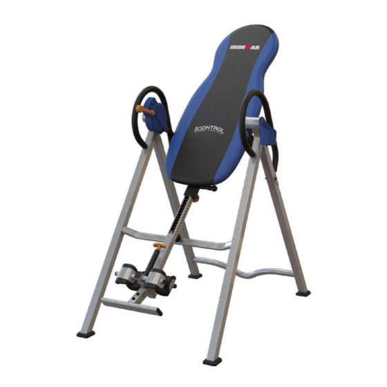
iControl Disk Brake
Inversion Table
5600.3‐050916
Item#5600
The specifications of this product may vary from this photo and are subject to change without notice.
IRONMAN, IRONMAN TRIATHLON and M-DOT are registered trademarks of World Triathlon Corporation.
This product is licensed by the World Triathlon Corporation.
Advertisement
Table of Contents

Related Manuals for Ironman Fitness 5600


Summary of Contents for Ironman Fitness 5600
- Page 1 Disk Brake Inversion Table 5600.3‐050916 Item#5600 The specifications of this product may vary from this photo and are subject to change without notice. IRONMAN, IRONMAN TRIATHLON and M-DOT are registered trademarks of World Triathlon Corporation.
- Page 2 ...
-
Page 3: Table Of Contents
TABLE OF CONTENTS SERVICE-------------------------------------------------------------------- 2 IMPORTANT SAFETY INSTRUCTIONS--------------------------- 3 LABEL PLACEMENT---------------------------------------------------- 6 OVERVIEW DRAWING------------------------------------------------- 7 PART LIST----------------------------------------------------------------- 9 HARDWARE LIST & TOOLS----------------------------------------- 11 ASSEMBLY-----------------------------------------------------------------12 HOW TO USE--------------------------------------------------------------21 OPERATION AND ADJUSTMENTS-------------------------------- 23 STORAGE----------------------------------------------------------------- 25 WARRANTY-------------------------------------------------------------- 26 PARTS REQUEST FORM-------------------------------------------- 27 1 ... -
Page 4: Service
SERVICE IMPORTANT: FOR NORTH AMERICA ONLY For damage or defective product, questions, replacement parts or any other service support, please contact our customer service department (8:00 AM - 5:00 PM Pacific Standard Time, Daily) by below methods: For Best Service Email: Service@paradigmhw.com Response time may vary. -
Page 5: Important Safety Instructions
IMPORTANT SAFETY INSTRUCTIONS This inversion table was designed and built for optimal safety. However, certain precautions apply whenever you operate this exercise equipment. Be sure to read the entire manual before assembling and operating this equipment. When using this equipment, basic precautions should always be followed, including the following: ... - Page 6 IMPORTANT SAFETY INSTRUCTIONS WARNING: Risk of personal injury – Keep children away from the machine while in use. WARNING: Risk of personal injury – Do not grab the brake handle for getting up from an inverted position, use the two handle bars instead. WARNING: Risk of personal injury - Keep body parts, hair, loose clothing and jewelry clear of all moving parts.
- Page 7 IMP P ORTANT SAFETY IN NSTRUCTI I ONS 5 ...
-
Page 8: Label Placement
LABEL PLACEMENT Maximum weight capacity is 275 lbs. AVERTISSEMENT Le poids maximum pout ce produit est 125 kgs. Pour le service a la clientèle For customer assistance call: composer le: 1-844-641-7922 1-844-641-7922 8 am - 5 pm PST Tous les jours Daily 8:00 h - 17 h (HNP) CET ÉQUIPEMENT EST DESTINÉ... -
Page 9: Overview Drawing
OVERVIEW DRAWING 7 ... - Page 10 OVERVIEW DRAWING 8 ...
-
Page 11: Part List
PART LIST Description Q'ty Description Q'ty Front Frame 29 Handlebar Cup Holder 30 Knob Ø45x3/8”x19L Rear Frame 31 Steel Bracket Cup Holder Rotation Cap 32 Bolt M6x30 Rectangle End Cap 50x25 33 Lock Mechanism Front Rod 34 Lock Handle Plastic Bar Rubber Heel Holder 35 Foam Bed Adjustable Boom... - Page 12 PART LIST Description Q'ty Description Q'ty 57 Washer Ø4.3xØ9xt0.3 63 Bolt M4x20 58 Round Cap 64 Locking Pin 59 Spring Washer Ø8.1xØ12.3x2.1 65 Upper Bed Frame End Cap 50 60 Screw ST3.5x10 66 Lower Bed Frame Bushing 61 Brake Strap 67 Rectangle End Cap 33.4 62 Cap 68 Screw ST4.2x2 ...
-
Page 13: Hardware List & Tools
HARDWARE LIST & TOOLS ... -
Page 14: Assembly
ASSEMBLY The product weighs more than 44lbs / 20kgs and should be assembled and moved by two or more people. Tool: Phillips Screwdriver Phillips Screwdriver 1 PC 1 PC 6mm Allen Wrench 1 PC Hex Wrench 1 PC Step 1: Attach two Front Foot Caps (53) and two Rear Foot Caps (49) to the Feet of the Front Frame (1) and Rear Frame (3). - Page 15 ASSEMBLY Tool: 5mm Allen Wrench Allen Wrench #5 1 PC 1 PC Allen Wrench #6 6mm Allen Wrench 1 PC 1 PC Hex Wrench 1 PC Step 2: Attach the Bed Frame (10) onto the Right Pivot Arm (12) and the Left Pivot Arm (19) by using two Lock Nuts (15), two Bolts (43), two Bolts (46) and two Washers (13);...
- Page 16 ASSEMB Fig. A Tool: Fig. B Phillips Screwdrive Phillips S Screwdriver ep 3: de the Loc ck Handle P Plastic Bar r (34) onto the Lock M Mechanism m (33). The e “U shape d” end of th he Lock andle Plast tic Bar (34) ) MUST be...
- Page 17 ASSEMBLY Tool: Allen Wrench #6 6mm Allen Wrench 1 PC 1 PC Hex Wrench 1 PC Step 4: Attach both of the Handlebars (29) onto the Rear Frame (3) with six Washers (13), two Lock Nuts (15), two Bolts (38) and two Bolts (46). Tighten the Bolts (46) with the 6mm Allen Wrench provided.
- Page 18 ASSEMBLY Tool: Hex Wrench 2 PCS Step 5: Remove the Square End Cap (41) on the back of the Adjustable Boom (8), and set it aside for Step 8. Slide the Rear Rod (9) through the large round hole on the side of the Adjustable Boom (8). Secure the Rear Rod (9) onto the Adjustable Boom (8) by using one Hex Bolt (40), two Washers (27) and one Lock Nut (16).
- Page 19 ASSEMBLY Tool: 6mm Allen Wrench Allen Wrench #6 1 PC 1 PC Hex Wrench 1 PC Step 6: Slide the Foot Bar (39) into the bottom of the Adjustable Boom (8) and align two of the holes on the Foot Bar (39) with the two holes on the Adjustable Boom (8). Secure the Foot Bar (39) in place using two Bolts (56), two Lock Nuts (15) and four Washers (13).
- Page 20 ASSEMBLY Step 7: Wrap Both the Rubber Heel Holders (7) with a Steel Bracket (31). Slide them onto the ends of the Front Rod (6) until the lock teeth are wedged into the slot on the Front Rod (6). Note: Make sure the lock teeth are wedged into the slots in the Front Rod (6) as shown in Fig. A and B before using the inversion table.
- Page 21 ASSEMBLY Step 8: Pull up on the Spring Knob (17) and insert the Front Rod (6) all the way into the empty square tube on the Adjustable Boom (8). Make sure the pin holes on the Front Rod (6) are facing upward when installing.
- Page 22 ASSEMBLY Step 9: Loosen the Knob (30). Pull out the Boom Spring Knob (18) and slide the Adjustable Boom (8) into the Bed Frame (10). Use the Height Sticker on the Adjustable Boom (8) as a guide to set the equipment to the appropriate user height.
-
Page 23: How To Use
HOW TO USE Set the Adjustable Boom to your height: 1. Turn the Knob counter-clockwise to loosen the Adjustable Boom. 2. Pull the Boom Spring Knob as you adjust the Adjustable Boom to the Adjustable desired height. Boom 3. Turn the Knob clockwise to secure the Boom Spring Knob Adjustable Boom. - Page 24 HOW TO USE How to control the amount of inversion: Push the Lever to the UNLOCKED position. When at the desired angle, pull the Lever to Control the inversion by using your left hand to the LOCKED position to lock the bed in place. grip the left handle bar on the left handlebar, while keeping your right hand on the Lever.
-
Page 25: Operation And Adjustments
OPERATION AND ADJUSTMENT Using he Handlebars For added convenience and safety, a set of Handlebars has been added to the inversion table. These Handlebars are located at the top of the Rear Frames. The Handlebars are there to help you return to the upright position from any degree of inversion. If you wish to return to the upright position, and the bed is moving too slowly, or not moving at all, simply grab the Handlebars and pull on them until you return to the upright position. - Page 26 ERATION AND AD DJUSTME ENT USIN NG THE E INVER RSION T TABLE Start by y lying fully y back on t the bed wi th your ha ands at you ur side, or resting on n your thig See Fig g.
-
Page 27: Storage
STORAGE Pull out the Locking Pin (64), and then fold the Front Frame (1) and the Rear Frame (3) together. Reinsert the Locking Pin (64) into the hole from which it was removed. If relocating the Inversion table, make sure the Lock Handle Plastic Bar (34) is in the LOCKED position during transport. -
Page 28: Warranty
WARRANTY MANUFACTURER’S LIMITED WARRANTY Paradigm Health & Wellness warrants to the original purchaser that this product is free from defects in material and workmanship when used for the purpose intended, under the conditions that it has been installed and operated in accordance with Paradigm’s Owner’s Manual. -
Page 29: Parts Request Form
PARTS REQUEST FORM Paradigm Health & Wellness, Inc. EMAIL THIS FORM WITH YOUR RECIEPT OF PURCHASE TO Service@paradigmhw.com * NAME: _______________________________________________________ ADDRESS: _____________________________________________________ CITY ______________ STATE ______________ ZIP ____________________ TELEPHONE: (Day) ____________________________________________ (Night) ___________________________________________ SERIAL#: ______________________________________________________ MODEL#: _____________________________________________________ PURCHASE DATE: ______________________________________________ PLACE OF PURCHASE: __________________________________________ PART # DESCRIPTION...
Need help?
Do you have a question about the 5600 and is the answer not in the manual?
Questions and answers