Ironman Fitness 5402 Owner's Manual
Inversion table
Hide thumbs
Also See for 5402:
- Owner's manual (20 pages) ,
- Owner's manual (20 pages) ,
- Owner's manual (26 pages)
Table of Contents
Advertisement
Advertisement
Table of Contents

Related Manuals for Ironman Fitness 5402


Summary of Contents for Ironman Fitness 5402
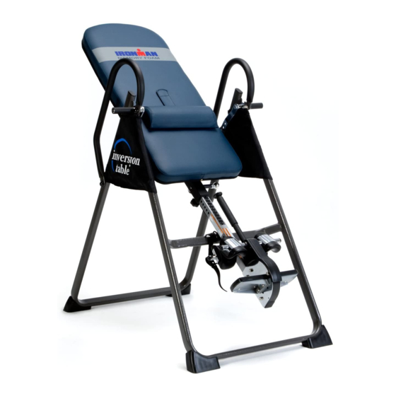
- Page 1 OWNER’S MANUAL Inversion Table Item#5402 The specifications of this product may vary from this photo and are subject to change without notice. IRONMAN, IRONMAN TRIATHLON and M-DOT are registered trademarks of World Triathlon Corporation. This product is licensed by the World Triathlon Corporation.
- Page 2 5402.2‐072214 ...
-
Page 3: Table Of Contents
TABLE OF CONTENTS SERVICE ------------------------------------------------------------------------- 2 LABEL PLACEMENT --------------------------------------------------------- 3 IMPORTANT SAFETY INSTRUCTIONS -------------------------------- 4 OVERVIEW DRAWING ------------------------------------------------------ 6 PARTS LIST -------------------------------------------------------------------- 7 PARTS, HARDWARE & TOOLS LIST------------------------------------- 8 ASSEMBLY ---------------------------------------------------------------------- 9 SAFETY OPERATING INSTRUCTIONS --------------------------------- 16 OPERATION & ADJUSTMENTS ------------------------------------------ 17 STORAGE &... -
Page 4: Service
SERVICE IMPORTANT: FOR NORTH AMERICA ONLY To request product service and order replacement parts, please call our customer service department at: 1-844-641-7922 Monday through Friday, 8:00 AM-5:00 PM Pacific Standard Time, service@paradigmhw.com or email us at: Please visit our website at www.paradigmhw.com. Please have the following information ready when requesting for service: Your name Phone number... -
Page 5: Label Placement
LABEL PLACEMENT... -
Page 6: Important Safety Instructions
IMPORTANT SAFETY INSTRUCTIONS This inversion table was designed and built for optimum safety. However, certain precautions apply whenever you operate the exercise equipment. Be sure to read the entire manual before assembling and operating this equipment. When using an appliance, basic precautions should always be followed, including the following: WARNING - To reduce the risk of injury to persons:... - Page 7 IMPORTANT SAFETY INSTRUCTIONS WARNING - Risk of personal injury - Keep body parts, hair, loose clothing and jewelry clear of all moving parts. NOTE: Maximum Weight Capacity for this product is 300lbs/136kgs. Maximum Rated Height for this product is 6’6”/198cm. WARNING: Before using this equipment you should consult with your personal physician to see if inversion equipment is appropriate for you.
-
Page 8: Overview Drawing
OVERVIEW DRAWING... -
Page 9: Parts List
PARTS LIST Description Description 001 Front U-Frame 032 Nylon Strap 002 Rear U-Frame 033 Loop Strap 003 Adjustable Boom 034 Strap Lock 004 Bed Frame 035 Foam Bed 005 Pivot Arm 036 Foam Grip 006 Adjustable Lock Plate 037 Protective Cover 007 Steel Heel Holder Bracket 038 Hex Head Bolt M8x23 008 Folding Arm... -
Page 10: Parts, Hardware & Tools List
PARTS, HARDWARE & TOOLS LIST Description Qty No. Description 063 Bolt M6x15 1 068 Screw ST4.8x20 064 Carriage Bolt M8x70 2 069 Shaft Nut Ø8 065 Bolt M6x30 1 070 Bolt M5x10 066 Spacer Ø22x16.8 2 071 Bolt M8x 50 067 Screw ST4.2x12 8 072 Pivot Arm Ring * Most of the components of the following parts list have already been assembled for your convenience. -
Page 11: Assembly
ASSEMBLY Tool: Multi Hex Tool with Phillips Screwdriver Step 1: Stand up the base of the machine by separating the Front and Rear U-Frames (1, 2). Pull the Front and Rear U-Frames (1, 2) as far apart from each others as possible. - Page 12 ASSEMBLY (55) Nut Cap Ø27xØ13.5 2 PCS Step 2: Install two Ø27xØ13.5 Nut Caps (55) onto M8 Lock Nuts (15). Slide one Protective Cover (37) on to each side of the base as shown, and pull down on the Protective Covers (37) until the bottom of the covers are slightly lower than the Folding Arms (8).
- Page 13 ASSEMBLY Step 4: Mount the Bed Frame (4) to the Rear U-Frame (2) by inserting the ends of the Pivot Arms (5) into the channels on the plates. The slotted portion of the rollers on the end of the Pivot Arms (5) should be inserted into the channels on the plates.
- Page 14 ASSEMBLY Step 6: Pull out the Large Spring Knob (18) and slide the Adjustable Boom (3) into the square bracket on the bottom of the Bed Frame (4) as shown. Slide the Adjustable Boom (3) upward until the desired height on the height scale is just below the bracket on the Bed Frame (4).
- Page 15 ASSEMBLY Tool: Multi Hex Tool with Phillips Screwdriver Wrench Step 7: Attach the top end of Handlebar (29) onto the Rear U-Frame (2) and Pivot Arm Ring (72) with one M8x23 Hex Head Bolt (38), one M8 Lock Nut (15), and two Ø20xØ8.5x1.5 Washers (13).
-
Page 16: Front U-Frame
ASSEMBLY Step 8: Attach the Nylon Strap (32) to the Strap Lock (34) by inserting the end of the Nylon Strap (32) up through the bottom of the Strap Lock (34), loop the Nylon Strap (32) over the Pre-assembled Loop Strap (33) and down through the Strap Lock (34). - Page 17 ASSEMBLY Step 10: Insert the Velcro strap from the Foam Bed (35) to the underneath of Lumbar Pad (47) and secure the Lumbar Pad (47) onto the Foam bed (35).
-
Page 18: Safety Operating Instructions
SAFETY OPERATING INSTRUCTIONS Incorrect Correct Pivot arm is NOT aligned correctly. Make sure the pivot arm is inserted all The pivot arm is not inserted all the way into the slot. Pivot arm is the way into the curved slot. aligned correctly when the groove sits directly on the curved slot and the pivot arm is able to rotate freely. -
Page 19: Operation & Adjustments
OPERATION & ADJUSTMENTS SHORTEN LENGTHEN THE STRAP For added safety, a nylon strap has been included to restrict the degree of inversion. This strap can be adjusted to different lengths to allow for a greater or lesser degree of inversion. To lengthen the Nylon Strap (32) feed the top end of Nylon Strap (32) into the strap lock, and pull on the lower end of the strap. -
Page 20: Pivot Arm
OPERATION & ADJUSTMENTS PIVOT ARMS The Pivot Arms (5) can be adjusted to allow for a greater or lesser degree of inversion. To adjust the Pivot Arms (5) simply pull out on them until the post is out of the hole, slide them up or down to the desired hole, push in until the post goes through the desired hole. - Page 21 OPERATION & ADJUSTMENTS BALANCING THE INVERSION TABLE The inversion table is like a very sensitively balanced fulcrum. It responds to very slight changes in weight distribution. So, it is very important to make sure that the height is adjusted properly. To do this, mount the inversion table, lock your ankles into the heel holders, and lie back with your hands at your sides.
- Page 22 OPERATION & ADJUSTMENTS SUGGESTIONS FOR USE 1. Begin slowly: invert only 15~20 degrees to begin with. Stay inverted only as long as you are comfortable. Return upright slowly. 2. Make gradual changes: increase the angle only if it is comfortable. Increase angle only a few degrees at a time. Increase the time of use 1~2 minutes up to ten over a period of weeks.
-
Page 23: Storage & Troubleshooting
STORAGE & TROUBLESHOOTING For your storage convenience, the inversion table can be folded down to place against a wall, under a bed, or in a storage area. “Any other servicing not described in this manual should be performed by an authorized service representative.” In case the Adjustable Handle (56) is too tight to release Rubber Heel Holder (31), please follow these steps:... -
Page 24: Warm Up
WARM UP Quadriceps Stretch With one hand against a wall for balance, reach behind you and pull your right foot up. Bring your heel as close to your buttocks as possible. Hold for 15 counts and repeat with left foot up. Inner Thigh Stretch Sit with the soles of your feet together with your knees pointing outward. -
Page 25: Warranty
WARRANTY MANUFACTURER’S LIMITED WARRANTY Paradigm Health & Wellness warrants to the original purchaser that this product is free from defects in material and workmanship when used for the purpose intended, under the conditions that it has been installed and operated in accordance with Paradigm’s Owner’s Manual. -
Page 26: Fax Form
FAX FORM IRONMAN PARTS REQUEST FAX FORM Please fax this form to (1-626-810-2166) OR YOU CAN EMAIL CUSTOMER SERVICE REQUESTS TO service@paradigmhw.com NAME: _______________________________________________________ ADDRESS: ____________________________________________________ CITY ______________ STATE ______________ ZIP ___________________ TELEPHONE: (Day) _____________________________________________ (Night) ____________________________________________ (Email Address) ____________________________________ SERIAL#: __________________________________________ MODEL#: __________________________________________ PURCHASE DATE: ______________________________________________ PURCHASE FROM: ______________________________________________...
Need help?
Do you have a question about the 5402 and is the answer not in the manual?
Questions and answers