
Related Manuals for SICK DME4000


Summary of Contents for SICK DME4000
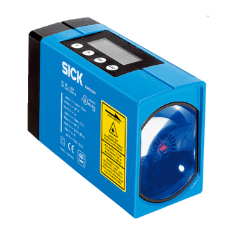
- Page 1 B E T R I E B S A N L E I T U N G / O P E R AT I N G I N S T R U C T I O N S DME4000 Entfernungs-Messgerät...
-
Page 2: German Seite
Betriebsanleitung DME4000 Dieses Werk ist urheberrechtlich geschützt. Die dadurch begründeten Rechte bleiben bei der Firma SICK AG. Eine Vervielfältigung des Werkes oder von Teilen dieses Werkes ist nur in den Grenzen der gesetzlichen Bestimmungen des Urheberrechtsgesetzes zulässig. Eine Abänderung oder Kürzung des Werkes ist ohne ausdrückliche schriftliche Zustimmung der Firma SICK AG untersagt. -
Page 3: Table Of Contents
Wartung ..............................40 Troubleshooting und Begriffserklärungen ..................40 Troubleshooting ........................... 40 Begriffserklärungen ........................41 8.2.1 PROFIBUS ......................... 41 8.2.2 RS 422 ........................42 8.2.3 SSI ..........................42 8.2.4 DeviceNet ......................... 43 8014584/ZN33/2017-07 © SICK AG • Deutschland • Irrtümer und Änderungen vorbehalten... - Page 4 9.2.2 Datenformat Master zu Slave ................. 47 9.2.3 Diagnosedaten ......................47 9.2.4 Definitionen/Fehler/Fehlerbehebung zu PROFIBUS-Fehlermeldungen ....49 Inbetriebnahme DME4000 PROFIBUS (Beispiel Siemens Step 7) ........50 Sleepmode ............................ 52 RS-422-Schnittstelle ........................52 9.5.1 Protokoll ........................52 9.5.2 Befehle ........................52 9.5.3...
-
Page 5: Einleitung
Bestell-Nummer Serien-Nummer Produktionsjahr/-monat Bestimmungsgemäße Verwendung Das DME4000 ist ein optoelektronischer Sensor, der zum Erfassen von Distanzen zu einer linear be- wegten Reflexionsfolie eingesetzt wird. Er darf nicht in explosionsgefährdeten Bereichen verwendet werden. Sicherheitshinweise Lesen Sie die Betriebsanleitung vor der Inbetriebnahme. -
Page 6: Laserwarnhinweis
Durch die schnelle Messwertermittlung ist das DME4000 für den direkten Betrieb in einem geschlossenen Lageregelkreis über die SSI- Schnittstelle z. B. mit einem Frequenzumrichter geeignet. Abbildung 1-1 Funktionsweise DME4000 © SICK AG • Deutschland • Irrtümer und Änderungen vorbehalten 8014584/ZN33/2017-07... -
Page 7: Bedienung
Betriebsanleitung Kapitel 2 DME4000 Bedienung Dieses Kapitel erklärt das Bedienfeld und die grundsätzliche Bedienung des DME4000. Detaillierte Informationen zur Inbetriebnahme und zum Betrieb des DME4000 finden Sie im Kapitel 4 „Inbetriebnahme“. Aufbau des Bedienfeldes LC-Display Eingabebereich Abbildung 2-1 – Display Das Bedienfeld ist in zwei Bereiche unterteilt: ... -
Page 8: Bedienfeld
Nach Anlegen der Betriebsspannung (oder nach Reset) erscheint folgende Anzeige im Display des DME4000: Infofeld 1 Statusanzeigen Infofeld 2 Funktionstasten Abbildung 2-2 – Anzeige nach Anlegen der Betriebsspannung Nach ca. 1 s ist das DME4000 betriebsbereit und zeigt den aktuellen Messwert an: 2.3.1 Statusanzeigen Anzeige Bedeutung Wird angezeigt Wird nicht angezeigt... - Page 9 Drücken von Blinkende Anzeige Service signalisiert einen Hardwaredefekt oder Service Über-/Untertemperatur. Tasten Führt durch die Menüstruktur, Code, Parametereingabe, Speichern von Parametern Verlassen eines Menüunterpunktes Auswahl von Menüpunkten, Eingabe von Zahlen 8014584/ZN33/2017-07 © SICK AG • Deutschland • Irrtümer und Änderungen vorbehalten...
-
Page 10: Menüstruktur
Menüstruktur Kapitel 3 Betriebsanleitung DME4000 Menüstruktur Flussdiagramm Auf der Innenseite der hinteren Umschlagklappe ist die Menüstruktur des DME4000 in Form eines Flussdiagramms dargestellt. Erklärungen zur Menüstruktur Code Schutz vor unbeabsichtigtem Verändern der eingestellten Parameter. Code: 314 Funktion: Menüzugang und Verändern der Parameter: Code 314 bestätigen mit Die erfolgreiche Eingabe des Codes wird im Display mit einem „!“... - Page 11 Warn-, Zustands- und Fehlerinformationen übertragen. Beschreibung siehe „9.2 PROFIBUS-Schnittstelle “. Bus Address Hier wird die PROFIBUS-Teilnehmeradresse eingestellt. Addr. 006 (default) (001-125) Inbetriebnahme-Beispiel mit Siemens Step 7 siehe Kapitel 9 „Anhang“. Hinweis 8014584/ZN33/2017-07 © SICK AG • Deutschland • Irrtümer und Änderungen vorbehalten...
- Page 12 Datenübertragung nur auf Anforderung Request Zyklische Datenübertragung gemäß der eingestellten Continuous Baudrate Protocol <STX><0x81><0x22><sign><7xBCD><ETX> Standard <sign><7xBCD><CR><LF> CRLF <sign><7xBCD> Nicht belegt Hinweis Für eine detaillierte Beschreibung siehe Kapitel 9 „Anhang RS-422-Schnittstelle“. © SICK AG • Deutschland • Irrtümer und Änderungen vorbehalten 8014584/ZN33/2017-07...
- Page 13 Funktionsbeschreibung siehe Kapitel 9.1 „Preset“ Laser aus, Messwert = 0, Quittierung über Ready Status Sleepmodus Funktionsbeschreibung siehe Kapitel 9.4 „Sleepmode“ (Nur SSI-Variante): Wird angezeigt, wenn unter 3.1.4 die Monitorschnittstelle Monitor ON gesetzt wird 8014584/ZN33/2017-07 © SICK AG • Deutschland • Irrtümer und Änderungen vorbehalten...
- Page 14 Ready Laser ausgeschaltet – Busfehler Datenübertragung OK Bus Status SSI: kein Clocksignal SSI: Clocksignal vorhanden PB/DN: kein Telegrammverkehr PB/DN: Telegrammverkehr CANopen: stopped mode CANopen: (pre-)operational mode Off (default) – © SICK AG • Deutschland • Irrtümer und Änderungen vorbehalten 8014584/ZN33/2017-07...
- Page 15 Aktiv 0 Function Distance siehe 3.4.3 Service (default) siehe 3.4.4 (nur SSI-Variante): Wird angezeigt, wenn unter 3.1.4 die Monitorschnittstelle Monitor On gesetzt wird Distance MF2 wird als Distanzschaltausgang verwendet. Funktion: 8014584/ZN33/2017-07 © SICK AG • Deutschland • Irrtümer und Änderungen vorbehalten...
- Page 16 Messfehler, Laser ausgeschaltet – Busfehler Datenübertragung OK Bus Status SSI: kein Clocksignal SSI: Clocksignal vorhanden PB/DN: kein Telegrammverkehr PB/DN: Telegrammverkehr CANopen: stopped mode CANopen: (pre-)operational mode Off (default) – © SICK AG • Deutschland • Irrtümer und Änderungen vorbehalten 8014584/ZN33/2017-07...
- Page 17 > 10 m/s und Verschmutzung. Plausibilitätsfehler führt zu Messwertausgabe 0. Normal 200 ms (Default) Keine Überprüfung Überprüfung im Messzyklus Fehlerunterdrückung max. 200 ms Temperatur Anzeige der aktuellen Geräteinnentemperatur. Reset kein Reset Rückstellung auf Default-Werte 8014584/ZN33/2017-07 © SICK AG • Deutschland • Irrtümer und Änderungen vorbehalten...
-
Page 18: Inbetriebnahme
DME4000 Inbetriebnahme Montage Das DME4000 und der Reflektor werden so befestigt, dass der Reflektor immer im Sichtfeld des Sen- sors ist. Das DME4000 wird so ausgerichtet, dass sich der (auch in großen Abständen) gut sichtbare Lichtfleck im Zentrum des Reflektors befindet. -
Page 19: Vorgehensweise Bei Der Ausrichtung
Vorgehensweise bei der Ausrichtung Bringen Sie Fahrzeug und Reflektor auf kleine Distanz. Richten Sie das DME4000 so aus, dass der Lichtfleck sich im Zentrum des Reflektors befindet. Vergrößern Sie die Entfernung von Fahrzeug zu Reflektor und beobachten dabei den Lichtfleck. -
Page 20: Elektrischer Anschluss
Kapitel 4 Betriebsanleitung DME4000 Elektrischer Anschluss DME4000 nach Anschlussschema anschließen. Verdrahtungshinweise beachten (siehe Kapitel 4.2.1 „Verdrahtungshinweise“), Stecker und Kabel siehe Kapitel 6.3.2 „Stecker/Leitungen“. Abbildung 4-5 – Anschlussschema DME4000-xx1/DME4000-xx3 (SSI/RS 422) Abbildung 4-6 – Anschlussschema DME4000-xx2 (PROFIBUS) Abbildung 4-7 – Anschlussschema DME4000-xx4 (DeviceNet M16- und M12-Stecker) ©... -
Page 21: Verdrahtungshinweise
1 = Adernpaar blk/wht 2 = Adernpaar red/vio 3 = Adernpaar pnk/gra 4 = Adernpaar brn/blu 5 = Isolierfolie 6 = Schirm 7 = PUR-Mantel Abbildung 4-11 – LTG-2308-MW, Bestell-Nr. 6026292 8014584/ZN33/2017-07 © SICK AG • Deutschland • Irrtümer und Änderungen vorbehalten... - Page 22 Adern gegeben. Ein einwandfreies und vollständiges Schirmkonzept ist für die störungsfreie Datenübertragung erforderlich. Speziell muss auf die Erdung des Kabelschirmes an Schaltschrank und DME4000 geachtet werden. Der Kabelschirm des vorkonfektionierten Kabels ist mit dem Metallstecker und damit mit dem DME4000-Gehäuse verbunden. Der Kabelschirm am Schaltschrank muss großflä- chig mit der Betriebserde verbunden werden.
-
Page 23: Profibus-Terminierung
Abbildung 4-15 – Keine „Schweineschwänzchen“, Schirm kurz und vollflächig anbinden, BEIDE Seiten erden Abbildung 4-16 – Schirmanschluss bei Kunststoffgehäusen 4.2.2 PROFIBUS-Terminierung Terminator Abbildung 4-17 – PROFIBUS-Terminierung (siehe Kapitel 6.3.2 „Stecker/Leitungen“) 8014584/ZN33/2017-07 © SICK AG • Deutschland • Irrtümer und Änderungen vorbehalten... -
Page 24: Beispiel
Sie mit die gewünschte 1. Ziffer (z.B. „3“) ein. Anzeige Gehen Sie mit eine Stelle weiter und geben Sie mit Schritt 5 die gewünschte 2. Ziffer (z.B. „1“) ein. Anzeige © SICK AG • Deutschland • Irrtümer und Änderungen vorbehalten 8014584/ZN33/2017-07... - Page 25 Schritt 6 die gewünschte 3. Ziffer (z.B. „4“) ein. Anzeige Drücken Sie um die 3. Ziffer „4“ zu bestätigen. Schritt 7 Anzeige Das Ausrufezeichen „!“ im Display bestätigt: Parametriermode. Hinweis 8014584/ZN33/2017-07 © SICK AG • Deutschland • Irrtümer und Änderungen vorbehalten...
-
Page 26: Technische Daten
1 x M12-Stecker 1 x M12-Stecker (SSI/RS 422) Stecker Stecker (DeviceNet) (DeviceNet) (CANopen) (PROFIBUS) 2 x M12-Stecker (Hiperface) Abbildung 6-2 –Maßzeichnungen Rückansicht DME4000 Abbildung 6-3 – Maßzeichnung DME4000 am Halter montiert © SICK AG • Deutschland • Irrtümer und Änderungen vorbehalten 8014584/ZN33/2017-07... -
Page 27: Anschlussschema
Technische Daten Betriebsanleitung Kapitel 6 DME4000 Anschlussschema Abbildung 6-4 – Anschlussschema DME4000-xx1/DME4000-xx3 (SSI/RS 422) Abbildung 6-5 – Anschlussschema DME4000-xx2 (PROFIBUS) Abbildung 6-6 – Anschlussschema DME4000-xx4 (DeviceNet M16- und M12-Stecker) 8014584/ZN33/2017-07 © SICK AG • Deutschland • Irrtümer und Änderungen vorbehalten... -
Page 28: Zubehör
Reflektoren Reflektor 0,3 x 0,3 m Diamond Grade, montiert Reflektor 0,6 x 0,6 m Diamond Grade, montiert Typ: PL 240 DG Bestell-Nr.: 1017910 Typ: PL 560 DG Bestell-Nr.: 1016806 © SICK AG • Deutschland • Irrtümer und Änderungen vorbehalten 8014584/ZN33/2017-07... - Page 29 Bestell-Nr.: 1022926 Typ: PL 560 DG-H Bestell-Nr.: 1023888 Reflexionsfolie Diamond Grade, Größe konfektionierbar Reflexionsfolie Diamond Grade, Bogen 749 x 914 mm Typ: REF-DG-K Bestell-Nr.: 4019634 Typ: REF-DG Bestell-Nr.: 5304334 8014584/ZN33/2017-07 © SICK AG • Deutschland • Irrtümer und Änderungen vorbehalten...
-
Page 30: Stecker/Leitungen
Typ: DOL-1608-G10MA Bestell-Nr.: 2027193 Typ: DOL-1608-G50MA Bestell-Nr.: 6032903 Steckeransicht Leitungsdose M16, 8-polig, gewinkelt, 5 m Leitungsdose M16, 8-polig, gewinkelt, 10 m Typ: DOL-1608-W05MA Bestell-Nr.: 2026743 Typ: DOL-1608-W10MA Bestell-Nr.: 2027194 Steckeransicht © SICK AG • Deutschland • Irrtümer und Änderungen vorbehalten 8014584/ZN33/2017-07... - Page 31 , 6 x 0,25 mm paarweise verdrillt, abgeschirmt Technische Daten bewegt –5 ... +70 °C Typ: LTG-2308-MW Bestell-Nr.: 6026292 Temperaturbereich festverlegt –40 ... +80 °C Mantel PUR kieselgrau Schirm verzinntes Kupfergeflecht 8014584/ZN33/2017-07 © SICK AG • Deutschland • Irrtümer und Änderungen vorbehalten...
- Page 32 Bestell-Nr.: 6027533 DeviceNet-Leitungsdose, M12, 5-polig, gerade, DeviceNet-Verbindungsleitung 6 m, Dose M12, 5-polig, Leitung 6 m, Dropcable gerade, Stecker M12, 5-polig, gerade, Dropcable Typ: DOL-1205-G06MK Bestell-Nr.: 6028326 Typ: DSL-1205-G06MK Bestell-Nr.: 6028327 © SICK AG • Deutschland • Irrtümer und Änderungen vorbehalten 8014584/ZN33/2017-07...
- Page 33 2 m, DOL-1208-G02MAH1 Bestell-Nr.: 6032448 Typ: LTG-3108-MW Bestell-Nr.: 6032456 bewegt 10 ... +70 °C 5 m, DOL-1208-G05MAH1 Bestell-Nr.: 6032449 Temperaturbereich festverlegt 40 ... +70 °C 10 m, DOL-1208-G10MAH1 Bestell-Nr.: 6032450 8014584/ZN33/2017-07 © SICK AG • Deutschland • Irrtümer und Änderungen vorbehalten...
- Page 34 Bestell-Nr.: 6028329 CANopen-Leitungsdose, 7/8'', 5-polig, gerade, PG16, konfek- CANopen-Leitungsstecker, 7/8'', 5-polig, gerade, PG16, tionierbar konfektionierbar Typ: DOS-7805-GK Bestell-Nr.: 6028331 Typ: STE-7805-GK Bestell-Nr.: 6028332 Pinbelegung 1 grn shield 4 wht CAN © SICK AG • Deutschland • Irrtümer und Änderungen vorbehalten 8014584/ZN33/2017-07...
-
Page 35: Befestigungstechnik
PUR schwarz Ø 6,8 mm Abschirmung Cu verzinnt 6.3.3 Befestigungstechnik Ausrichthalterung DME4000 Typ: BEF-DME Bestell-Nr.: 2040695 Ausrichthalterung DME5000 Befestigungs-Kit Sockelplatte DME4000 (benötigt für DME4000) Typ: BEF-AH-DME5 Bestell-Nr.: 2027721 Typ: BEF-DME4000 Bestell-Nr.: 2040738 8014584/ZN33/2017-07 © SICK AG • Deutschland • Irrtümer und Änderungen vorbehalten... -
Page 36: Wetterschutzgehäuse
Technische Daten Kapitel 6 Betriebsanleitung DME4000 6.3.4 Wetterschutzgehäuse Wetterschutzgehäuse DME4000 Typ: WSG-DME5 Bestell-Nr.: 2027800 6.3.5 Umlenkspiegel Umlenkung Lichtaustritt nach oben Typ: USP-DME5 Bestell-Nr.: 2027710 © SICK AG • Deutschland • Irrtümer und Änderungen vorbehalten 8014584/ZN33/2017-07... -
Page 37: Technische Daten Dme4000-1Xx
Schock: EN 600 68-2-27/-2-29, Sinus: EN 600 68-2-6, Rauschen: EN 600 68-2-64 Gewicht ca. 1650 g Statistischer Fehler 1 σ, Umfeldbedingungen konstant minimale Einschaltzeit: 10 min. Verpolsicher Darf U -Toleranzen nicht über- oder unterschreiten Nicht verpolgeschützt Max. 100 nF/20 mH 8014584/ZN33/2017-07 © SICK AG • Deutschland • Irrtümer und Änderungen vorbehalten... -
Page 38: Technische Daten Dme4000-2Xx
Schock: EN 600 68-2-27/-2-29, Sinus: EN 600 68-2-6, Rauschen: EN 600 68-2-64 Gewicht ca. 1650 g Statistischer Fehler 1 σ, Umfeldbedingungen konstant minimale Einschaltzeit: 10 min. Verpolsicher Darf U -Toleranzen nicht über- oder unterschreiten Nicht verpolgeschützt Max. 100 nF/20 mH © SICK AG • Deutschland • Irrtümer und Änderungen vorbehalten 8014584/ZN33/2017-07... -
Page 39: Technische Daten Dme4000-3Xx
Sinus: EN 600 68-2-6, Rauschen: EN 600 68-2-64 Gewicht ca. 1650 g Statistischer Fehler 1 σ, Umfeldbedingungen konstant minimale Einschaltzeit: 10 min. Verpolsicher Darf U -Toleranzen nicht über- oder unterschreiten Nicht verpolgeschützt Max. 100 nF/20 mH 8014584/ZN33/2017-07 © SICK AG • Deutschland • Irrtümer und Änderungen vorbehalten... -
Page 40: Wartung
(Innentemperatur < –15 °C: Aufwärmphase abwarten. Evtl. außerhalb Spezifikation Gerät mit Heizung verwenden. Gerät zu warm (Innentemperatur > 80 °C: Gerät abkühlen Auswirkung: Messwertausga- be wird auf Null gesetzt. © SICK AG • Deutschland • Irrtümer und Änderungen vorbehalten 8014584/ZN33/2017-07... -
Page 41: Begriffserklärungen
Die angegebene Leitungslänge kann durch den Einsatz von Repeatern vergrößert werden. Es wird empfohlen, nicht mehr als 3 Repeater in Serie zu schalten. Das DME unterstützt alle in Tabelle 2 ge- nannten Übertragungsgeschwindigkeiten. 8014584/ZN33/2017-07 © SICK AG • Deutschland • Irrtümer und Änderungen vorbehalten... -
Page 42: Ssi
= Verzögerungszeit für den 1. Takt, max. 540 ns, für alle weiteren max. 360 ns Gn = hochwertigstes Bit im Gray-Code T = Periodendauer des Taktsignals GO = niederwertigstes Bit im Gray-Code tm = Monoflop-Zeit 15 µs bis 25 µs Tp = Taktpause © SICK AG • Deutschland • Irrtümer und Änderungen vorbehalten 8014584/ZN33/2017-07... -
Page 43: Devicenet
Verkürzte Menü-Struktur Das DME4000 kann nur über einen M12-Anschluss mit der Steuerung verbunden werden. Aus diesem Grund sind nur ausgewählte Einstellungen im Menü enthalten. Die Menüebenen „Serial“, „MF1“ und „MF2“ sind nicht implementiert. Die Nummerierung der Menü-Ebenen ist identisch mit denen der Standard-Variante. - Page 44 Troubleshooting und Begriffserklärungen Kapitel 8 Betriebsanleitung DME4000 Übersicht der verfügbaren Menü-Ebenen Menüebene Bezeichnung 3.1. CANOpen 3.5. Resolution 3.6. Offset 3.7. Plausibility Temperatur Reset © SICK AG • Deutschland • Irrtümer und Änderungen vorbehalten 8014584/ZN33/2017-07...
-
Page 45: Anhang
PROFIBUS-Schnittstelle Die PROFIBUS-Anbindung DME4000 erfolgt gemäß ENCODER-Profil. Dabei kann DME4000 wahlweise als Klasse-1- oder Klasse-2- (empfohlen) Encoder arbeiten. DME4000 ist dabei vom Typ linearer Abso- lut-Encoder. Angelehnt an das ENCODER-Profil (Klasse 2) ist ein ebenfalls implementiertes SICK-Profil. Beide Profilarten münden in die gleiche GSD-Datei. Im SICK-Profil ist neben einer von SPS gesteuerten Laserabschaltung auch die direkte Übertragung von Zustandsinformationsbits im zyklischen Messtele-... - Page 46 Ausnahme: PROFIBUS-Adresse und Offset bei aktivierter Preset-Funktion. Zusätzlich Statusbits 25 ... 31 Input-Daten und Steuerbits 29 ... 31 Output-Daten. Empfohlene Einstellung: SICK-Profil Class 2: Dieses Profil bietet folgende Vorteile: in 4-Byte-Input-Daten sind Messwert und Diagnosebits enthalten, in 4-Byte-Output-Daten ist Preset-Aktivierung, Laser-ein/aus-Funktion enthalten, ...
-
Page 47: Datenformat Slave Zu Master
Wertebereich +/ 250m (siehe auch Parameterdaten Preset-Mode) 9.2.3 Diagnosedaten (DDLM_Slave_Diag) Encoder-Profil Diagnose Class 1 Octet 1 ... 16 Octet 7... 16 Class 2 Octet 1 ... 63 Octet 7... 63 8014584/ZN33/2017-07 © SICK AG • Deutschland • Irrtümer und Änderungen vorbehalten... - Page 48 Octet 58 … 59 Temperatur (2er Komplement) Octet 60 Pegel Messkanal (2er Komplement) Octet 61 MF-Status Octet 62 Bit 7 Laser ein Laser aus Octet 63 Bit 0 ... 6 nicht verwendet © SICK AG • Deutschland • Irrtümer und Änderungen vorbehalten 8014584/ZN33/2017-07...
-
Page 49: Definitionen/Fehler/Fehlerbehebung Zu Profibus-Fehlermeldungen
Wird mit Octet 9, Bit 7 deaktiviert. Auswirkung: Der per GSD eingestellte Offsetwert wird nicht zum Gerät übertragen. Anwendung: bei Verwendung der Preset-Funktion bleibt der bei Preset ermittelte Offsetwert gültig. 8014584/ZN33/2017-07 © SICK AG • Deutschland • Irrtümer und Änderungen vorbehalten... -
Page 50: Inbetriebnahme Dme4000 Profibus (Beispiel Siemens Step 7)
Service MF1: UpperTemperature Service MF2: Plausibility Siehe 3 –Menüstruktur: 3.4.4 Service MF2: Ready Service MF2: Laser Service MF2: Level Service MF2: Bus Status Service MF2: LowerTemperature Service MF2: UpperTemperature © SICK AG • Deutschland • Irrtümer und Änderungen vorbehalten 8014584/ZN33/2017-07... - Page 51 Siehe 3 – Menüstruktur: 3.3.3 MF1 Dist. LowerLimit MF2 Dist. UpperLimit Siehe 3 – Menüstruktur: 3.4.3 MF2 Dist. LowerLimit Preset Siehe 3 – Menüstruktur: 3.3.2 (Steps: entsprechend Auflösung) (MF1: Preset) 8014584/ZN33/2017-07 © SICK AG • Deutschland • Irrtümer und Änderungen vorbehalten...
-
Page 52: Sleepmode
Betriebsanleitung DME4000 Sleepmode Mit der Funktion Sleepmode kann der Messlaser des DME4000 über den Eingang MF1 aus- und einge- schaltet werden. Bei ausgeschaltetem Laser ist das DME im Stand-by-Betrieb, die Ready-Anzeige im Display erlischt. Um die Funktion zu überwachen, kann MF2 mit „Ready“ die Betriebsbereitschaft bei eingeschaltetem Laser signalisieren. -
Page 53: Beispiele Für Befehle (Standard-Protokoll)
Beispiel-39 dB ⇒ 8123D9 ⇒ 0x100 − 0xD9 = 0x27 =39 Service-Status zum DME<STX><0x01><0x23><ETX> vom DME<STX><0x81><0x23><0x..><ETX> BeispielIcon MF2 und Icon PLB sind sichtbar auf dem Display: 812542 ⇒ 0x42 = 10000010 binär 8014584/ZN33/2017-07 © SICK AG • Deutschland • Irrtümer und Änderungen vorbehalten... -
Page 54: Devicenet
Grundlage ist die DeviceNet-Spezifikation 2.0, Errata 5. Der Produktname ist „DME4000“. 9.6.2 Konfiguration Die Konfiguration und Inbetriebnahme des DME4000 als DeviceNet-Slave wird anhand der Alan- Bradley-Software „RS Networx for DeviceNet (Revision 4.12)“ gezeigt: Vorgehensweise: DME4000-xx4 8-poligen M16-Gerätestecker aufstecken und anschließen. - Page 55 LowerLimit Parametrierung von MF1 und MF2 Gerätevarianten DME4000-xx5 sind nur mit einem 5-poligen DeviceNet-Stecker ausgerüstet. Die Multi- ACHTUNG funktionsein- und -ausgänge MF1 und MF2 sind hardwaremäßig nicht verfügbar. Die Parametrierung von MF1 und MF2 ist trotzdem möglich und das Ergebnis kann im Diagnosebyte (siehe Kapitel 9.6.3 „Datenaustausch“) über den Bus abgefragt werden.
-
Page 56: Datenaustausch
Plausibilitätsfehler signalisiert, da keine Messung möglich ist, parallel wird Messwert 0 ausgegeben. 9.6.4 Polled Mode Der Prozessdatenaustausch zwischen DME4000 und DeviceNet-Master erfolgt standardmäßig über eine Polled I/O connection. Dabei werden die Slaves zyklisch vom Master abgefragt. 9.6.5 Change of State Mode Im Change of State Mode (COS/Delta) werden Daten zyklisch gesendet oder wenn der Wert des Para- meters Delta überschritten wird. -
Page 57: Sleepmode (Laser Aus)
DescriptionSet single Attribute Class65 Instance1 Attribute13 >Execute<-MeldungExecution was completed 9.6.7 Sleepmode (Laser aus) Die Funktion Sleepmode kann mit dem „Class Instance Editor“ aktiviert werden: Laser aus 8014584/ZN33/2017-07 © SICK AG • Deutschland • Irrtümer und Änderungen vorbehalten... -
Page 58: Parameter Im Dme4000 Speichern
Laser ein 9.6.8 Parameter im DME4000 speichern Mit dem Befehl „Download“ im Fenster „Parameters“ werden die Parameter zum DME4000 herunterge- laden und sind dort flüchtig gespeichert. Mit dem „Class Instance Editor“ können die Parameter nichtflüchtig (permanent) im DME4000 gespei- chert werden (Vorgehensweise siehe Screenshot). - Page 59 Fehlerstatus DescriptionGet single Attribute Class64 Instance1 Attribute:12 Received InformationBeispiel: 0 x 09 0000 1001 Icon BUS und RDY sind im Display sichtbar. 8014584/ZN33/2017-07 © SICK AG • Deutschland • Irrtümer und Änderungen vorbehalten...
- Page 60 Received InformationZeit: 0 x 0142 = 322 x 6 min = 1932 min = 32,2 h z.B. 01 02 03 04 = 0 x 04030201 = 67305985 x 6 min = 403835910 min = 6730598,5 h © SICK AG • Deutschland • Irrtümer und Änderungen vorbehalten 8014584/ZN33/2017-07...
-
Page 61: Hiperface
Die entsprechend gekennzeichneten Befehle beinhalten den Parameter „Code 0“. Code 0 ist ein Byte, das zur zusätzlichen Absicherung wichtiger Systemparameter gegen versehentliches Überschreiben ins Protokoll eingefügt ist. Bei Auslieferung ist „Code 0“ = 55h. 8014584/ZN33/2017-07 © SICK AG • Deutschland • Irrtümer und Änderungen vorbehalten... -
Page 62: Übersicht Der Hiperfacestandard-Statusmeldungen
Daten Angegebenes Datenfeld in seiner Größe nicht veränderbar Daten Angegebene Wortadresse außerhalb Datenfeld Daten Zugriff auf nicht existierendes Datenfeld Daten Gebertemperatur kritisch Vorausfall Weitere Fehlercodes siehe Kapitel 8.1 „Troubleshooting“. © SICK AG • Deutschland • Irrtümer und Änderungen vorbehalten 8014584/ZN33/2017-07... -
Page 63: Canopen
Anhang Betriebsanleitung Kapitel 9 DME4000 CANopen 9.8.1 Datenaustausch Das Objektverzeichnis ist unterteilt in Communication Segment“ mit allen CANopen-relevanten Parame- tern und in „Manufacturer Segment“ mit allen DME-spezifischen Parametern: 8014584/ZN33/2017-07 © SICK AG • Deutschland • Irrtümer und Änderungen vorbehalten... -
Page 64: Messwertausgabe
Measurement value 0x2001 Diagnostic data 9.8.3 Konfiguration Die Konfiguration und die Inbetriebnahme des DME4000 als CANopen-Slave wird über den SDO-Dienst des CANopen gestartet (siehe dazu die CIA-301 Spezifikation). Die Device-spezifischen Informationen sind in der EDS-Datei enthalten. 9.8.4 Parameter Folgende Parameter können über den SDO-Service (Service Data Object) ausgewählt werden: Index (Hex) Kapitel für weitere Informationen... -
Page 65: Zusätzliche Diagnosedaten
0x2201, Subindex 003 Status „telegram traffic“ 0x2201, subindex 004 Error status „Attenuation“ 0x2201, Subindex 005 Error status „Plausibility“ 0x2201, Subindex 006 Status „Ready“ 0x2202 Temperature 0x2203 Operating Hours 0x2204 Speed 8014584/ZN33/2017-07 © SICK AG • Deutschland • Irrtümer und Änderungen vorbehalten... - Page 66 Troubleshooting and Explanation of Terms ....................103 Troubleshooting ..........................103 Explanation of Terms ........................104 8.2.1 PROFIBUS ........................... 104 8.2.2 RS 422 ..........................105 8.2.3 SSI ............................105 SICK AG • Germany • Subject to change without notice 8014584/ZN33/2017-07...
- Page 67 Data Format Master to Slave .................... 110 9.2.3 Diagnosis Data ........................110 9.2.4 Definitions/Errors/Correct Errors of PROFIBUS Error Messages ........112 Operation Startup of DME4000 PROFIBUS (Example: Siemens Step 7) ........113 Sleep mode ............................115 RS-422 Interface ..........................115 9.5.1 Protocol ..........................115 9.5.2...
-
Page 68: Introduction
Production year/month Use in Accordance with Regulations The DME4000 is an opto-electronic sensor, which is used for detecting distances to reflective tape that is moved linearly. It may not be used in areas subject to the danger of explosions. Safety Instructions ... -
Page 69: Laser Warning
Complies with 21CFR1040.10 and 1040.11 except for deviations pursuant to Laser Notice 50, dated June 24, 2007. Laser class 2 (EN/IEC 60825-1:2014) Identical laser class for issue EN/IEC 60825-1:2007 8014584/ZN33/2017-07 © SICK AG • Germany • Subject to change without notice... -
Page 70: Mode Of Operation
DME4000 is suitable for direct opera- tion in a closed-loop position control via the SSI interface, e.g., with a frequency converter. Illustration 1.1 – DME4000 Mode of Operation © SICK AG • Germany • Subject to change without notice 8014584/ZN33/2017-07... -
Page 71: Operation
Operating Instructions Chapter 2 DME4000 Operation This section explains the control panel and basic operation of the DME4000. You can find detailed information about the operation startup and operation of the DME4000 in Chapter 4 “Operation Startup”. Operating Panel Structure... -
Page 72: Control Panel
Operation Chapter 2 Operating Instructions DME4000 Control Panel The following display of the DME4000 appears after you connect operating voltage (or after a reset): Information field 1 Status indicators Information field 2 Function keys Illustration 2.2 – Display after Connection of Operating Voltage The DME4000 is ready to operate after approx. - Page 73 Keys Prompts through the menu structure, code, parameter entry, storing of parameters Exit a menu subitem Selection of menu items and entry of numbers 8014584/ZN33/2017-07 © SICK AG • Germany • Subject to change without notice...
-
Page 74: Menu Structure
Operating Instructions DME4000 Menu Structure Flow Chart The menu structure of the DME4000 is displayed in the form of a flow chart on the inside of the back cover. Explanations about the Menu Structure Code Protection against unintentional changes to the set parameters. - Page 75 Bus Address The Profile bus subscriber address is set here. Addr. 006 (default) (001-125) Note For an operation startup example with Siemens Step 7 (see Chapter 9.5 “RS-422 Interface”). 8014584/ZN33/2017-07 © SICK AG • Germany • Subject to change without notice...
- Page 76 Cyclical data transfer in accordance with the defined baud rate setting Continuous Protocol <STX><0x81><0x22><sign><7xBCD><ETX> Standard <sign><7xBCD><CR><LF> CRLF <sign><7xBCD> unused Note For a detailed description, see Chapter 9.5 RS-422 Interface. © SICK AG • Germany • Subject to change without notice 8014584/ZN33/2017-07...
- Page 77 Sleep Mode For a function description, see “Explanation of Terms – Sleep Mode”. (Only SSI variant): Is displayed when the monitor interface is set to ON under 3.1.4. Monitor 8014584/ZN33/2017-07 © SICK AG • Germany • Subject to change without notice...
- Page 78 Data transmission OK Bus Status SSI: no clock signal SSI: clock signal PB/DN: no telegram traffic PB/DN: telegram traffic CANopen: stopped mode CANopen: (pre-)operational mode Off (default) – © SICK AG • Germany • Subject to change without notice 8014584/ZN33/2017-07...
- Page 79 Service Freely settable status messages in “OR” link, which provide information about the sensor state. Active Not active On (default) Pre-failure message Laser OK laser diode Laser – 8014584/ZN33/2017-07 © SICK AG • Germany • Subject to change without notice...
- Page 80 Movement direction “+/-“: Measured value in both directions – Resolution The resolution setting affects all interfaces. Possible settings: 50 ... 5000 µm, default 100 µm © SICK AG • Germany • Subject to change without notice 8014584/ZN33/2017-07...
- Page 81 200 ms (Default) No check Check in measurement cycle Error suppression max. 200 ms. Temperature Display of the current sensor temperature. Reset No reset Reset to default values 8014584/ZN33/2017-07 © SICK AG • Germany • Subject to change without notice...
-
Page 82: Operation Startup
The DME4000 and the reflector are mounted in such a way that the reflector is always in the detection field of the sensor. The DME4000 is aligned in such a way that there is a clearly visible light spot in the middle of the reflector (even at greater distances). -
Page 83: Arrangement Of The Positions Of Neighboring Distance Measuring Sensors
A minimum beam distance of 100 mm should be maintained for the data transmission photoelectric switches of the ISD300 / ISD400-1xxx / ISD400-6xxx series, independent of the maximum range s 8014584/ZN33/2017-07 © SICK AG • Germany • Subject to change without notice... -
Page 84: Electric Connection
Operating Instructions DME4000 Electric Connection Connect the DME4000 according to the connection diagram. Note the wiring notes (see Chapter 4.2.1); refer to Chapter 6.3.2 “Plugs/Cables” for information about the plugs and cables. Illustration 4.5 – DME4000-xx1/DME4000-xx3 Connection Diagram (SSI/RS 422) Illustration 4.6 –... -
Page 85: Wiring Notes
3 = Wire pair pnk/gra 4 = Wire pair brn/blu 5 = Insulating film 6 = Shield 7 = PUR sheathing Illustration 4.11 – LTG-2308-MW, Part no. 6026292 8014584/ZN33/2017-07 © SICK AG • Germany • Subject to change without notice... - Page 86 Special attention must be paid to grounding of the cable shield to the switching cabinet and the DME4000. The cable shield of the prefabricated cable is connected with the metal plug and consequently with the DME4000 housing.
-
Page 87: Profibus Terminator Connection
BOTH sides Illustration 4.16 – Shield connection for plastic housing 4.2.2 PROFIBUS Terminator Connection Terminator Illustration 4.17 –PROFIBUS Terminator Connection (refer to the accessories in Chapter 6.3.2 “Plugs/Cables“) 8014584/ZN33/2017-07 © SICK AG • Germany • Subject to change without notice... -
Page 88: Example
3x for the password “000” (only parameter view), enter the desired 1st digit Step 4 (e.g., “3”) with Display Advance one place with and enter the desired 2nd digit (e.g., “1”) with Step 5 Display © SICK AG • Germany • Subject to change without notice 8014584/ZN33/2017-07... - Page 89 3rd digit (e.g., “4”) with Step 6 Display Press to confirm the desired 3rd digit (e.g., “4”). Step 7 Display The exclamation mark “!” in the display confirms: parameterizing mode Note 8014584/ZN33/2017-07 © SICK AG • Germany • Subject to change without notice...
-
Page 90: Specifications
(DeviceNet) (DeviceNet) (CANopen) 2 x M12 plug (Hiperface) Illustration 6.2 – DME4000 Dimensional Drawings Rear View Illustration 6.3 – Dimensional Drawing of DME4000 Mounted on Bracket © SICK AG • Germany • Subject to change without notice 8014584/ZN33/2017-07... -
Page 91: Connection Diagram
Connection Diagram Illustration 6.4 – DME4000-xx1/DME4000-xx3 Connection Diagram (SSI/RS 422) Illustration 6.5 – DME4000-xx2 Connection Diagram (PROFIBUS) Illustration 6.6 – DME4000-xx4 Connection Diagram (DeviceNet M16 and M12 plug) 8014584/ZN33/2017-07 © SICK AG • Germany • Subject to change without notice... -
Page 92: Accessories
Reflector 0,3 x 0,3 m Diamond Grade, mounted Reflector 0,6 x 0,6 m Diamond Grade, mounted Typ: PL 240 DG Part no.: 1017910 Typ: PL 560 DG Part no.: 1016806 © SICK AG • Germany • Subject to change without notice 8014584/ZN33/2017-07... -
Page 93: Plugs/Cables
PROFIBUS, SSI and RS 422 M16 cable receptacle, 8-pin, straight M16 cable receptacle, 8-pin, angled Typ: DOS-1608-GA Part no.: 6025726 Typ: DOS-1608-WA Part no.: 6025727 Connector view Connector view 8014584/ZN33/2017-07 © SICK AG • Germany • Subject to change without notice... - Page 94 Variable –5 ... +70 °C Typ: LTG-2308-MW Part no.: 6026292 Temperature range Not variable –40 ... +80 °C Sheathing PUR grey Shield Tined cupper net © SICK AG • Germany • Subject to change without notice 8014584/ZN33/2017-07...
- Page 95 DeviceNet connection cable 6 m, M12 receptacle, 5-pin, cable 6 m, Dropcable straight, M12 plug, 5-pin, straight, Dropcable Typ: DOL-1205-G06MK Part no.: 6028326 Typ: DSL-1205-G06MK Part no.: 6028327 8014584/ZN33/2017-07 © SICK AG • Germany • Subject to change without notice...
- Page 96 2 m, DOL-1208-G01MAH1 Part no.: 6032448 Type: LTG-3108-MW Part no.: 6032456 5 m, DOL-1208-G05MAH1 Part no.: 6032449 Temperature range variable 10 ... +70 °C © SICK AG • Germany • Subject to change without notice 8014584/ZN33/2017-07...
- Page 97 CANopen female connector, 7/8'', 5-pin, straight, PG16, CANopen male connecotr, 7/8'', 5-pin, straight, PG16, sizeable sizeable Typ: DOS-7805-GK Part no.: 6028331 Typ: STE-7805-GK Part no.: 6028332 Pin assignment 8014584/ZN33/2017-07 © SICK AG • Germany • Subject to change without notice...
-
Page 98: Mounting
DME4000 alignment bracket Type: BEF-DME Part no.: 2040695 DME4000 alignment bracket Mounting kit for baseplate (needed for DME4000) Typ: BEF-AH-DME5 Part no.: 2027721 Typ: BEF-DME4000 Part no.: 2040738 © SICK AG • Germany • Subject to change without notice 8014584/ZN33/2017-07... -
Page 99: Weather-Protecting Hood
Operating Instructions Chapter 6 DME4000 6.3.4 Weather-Protecting Hood DME4000 weather-protecting hood Type: WSG-DME5 Part no.: 2027800 6.3.5 Corner Mirror Deflection of light emission upward Typ: USP-DME5 Part no.: 2027710 8014584/ZN33/2017-07 © SICK AG • Germany • Subject to change without notice... -
Page 100: Specifications Dme4000-1Xx
Statistical error, constant ambient conditions, minimum switch-on time 10 min Reverse-polarity protected May not exceed or fall short of V tolerances Not reverse-polarity protected Max. 100 nF/20 mH © SICK AG • Germany • Subject to change without notice 8014584/ZN33/2017-07... -
Page 101: Specifications Dme4000-2Xx
Statistical error, constant ambient conditions, minimum switch-on time 10 min Reverse-polarity protected May not exceed or fall short of V tolerances Not reverse-polarity protected Max. 100 nF/20 mH 8014584/ZN33/2017-07 © SICK AG • Germany • Subject to change without notice... -
Page 102: Specifications Dme4000-3Xx
Statistical error, constant ambient conditions, minimum switch-on time 10 min Reverse-polarity protected May not exceed or fall short of V tolerances Not reverse-polarity protected Max. 100 nF/20 mH © SICK AG • Germany • Subject to change without notice 8014584/ZN33/2017-07... -
Page 103: Maintenance
It might be necessary to use the sensor with heating Sensor too warm (internal temperature > 80 °C: Let sensor cool down Effect: Measured value output is set to zero 8014584/ZN33/2017-07 © SICK AG • Germany • Subject to change without notice... -
Page 104: Explanation Of Terms
The 5 V supply voltage can be loaded with 100 mA and be used for optic coupling modules if required. Terminator: See Accessories. If there are more than 32 subscribers, repeaters (power boosters) must be used to connect the individ- ual bus segments. © SICK AG • Germany • Subject to change without notice 8014584/ZN33/2017-07... -
Page 105: Ssi
T = period duration of the clock pulse signal GO = lowest value bit in gray code tm = monoflop time 15 µs to 25 µs Tp = clock pulse space 8014584/ZN33/2017-07 © SICK AG • Germany • Subject to change without notice... -
Page 106: Devicenet
Settings of Node-ID and Baudrate at the display are valid after a restart of the DME. Reduced menu structure The DME4000 is only available with one M12 connector, so only relevant settings are part of the menu. Menu items “MF1”, “MF2” and “serial” are removed. The numbering of the menu is identical with the standard DME4000 and the manual. - Page 107 Troubleshooting and Explanation of Terms Operating Instructions Chapter 8 DME4000 Implemented menu structure Menu 3.1. CANOpen 3.5. Resolution 3.6. Offset 3.7. Plausibility Temperature Reset 8014584/ZN33/2017-07 © SICK AG • Germany • Subject to change without notice...
-
Page 108: Appendix
Stop the vehicle at the preset position. MFActivate MF1, e.g., via the proximity initiator, photoelectric switch or switch. The output value of the DME4000 is equal to the set preset value at this position. Note The multifunctional input works edge-triggered: Active 0:... - Page 109 PROFIBUS address and offset with activated preset mode. In addition, status bits 25 … 31 input data and control bits 29 …31 output data. Recommended setting: SICK Profile Class 2: This profile provides the following advantages: Measurement value and diagnosis bits are contained in the 4 bytes input data.
-
Page 110: Data Format Slave To Master
Value range (also refer to the parameter data for the preset mode) 9.2.3 Diagnosis Data (DDLM_Slave_Diag) Encoder-profile Diagnosis Class 1 Octet 1 ... 16 Octet 7... 16 Class 2 Octet 1 ... 63 Octet 7... 63 © SICK AG • Germany • Subject to change without notice 8014584/ZN33/2017-07... - Page 111 Temperature (2 complement) Octet 61 Measurement channel level (2 complement) Octet 62 MF status Octet 63 Bit 7 Laser on Laser off Bit 0 ... 6 Not used 8014584/ZN33/2017-07 © SICK AG • Germany • Subject to change without notice...
-
Page 112: Definitions/Errors/Correct Errors Of Profibus Error Messages
Effect: The offset value set per GSD is not transmitted to sensor Application: When the preset function is used, the offset value set during the preset remains valid © SICK AG • Germany • Subject to change without notice 8014584/ZN33/2017-07... -
Page 113: Operation Startup Of Dme4000 Profibus (Example: Siemens Step 7)
Service MF2: Plausibility See 3 – Menu Structure: 3.4.4 Service MF2: Ready Service MF2: Laser Service MF2: Level Service MF2: Bus Status Service MF2: LowerTemperature Service MF2: UpperTemperature 8014584/ZN33/2017-07 © SICK AG • Germany • Subject to change without notice... - Page 114 MF1 Dist. LowerLimit MF2 Dist. UpperLimit See 3 – Menu Structure: 3.4.3 MF2 Dist. LowerLimit Preset See 3 – Menu Structure: 3.3.2 (Steps: corresponding to resolution) (MF1: Preset) © SICK AG • Germany • Subject to change without notice 8014584/ZN33/2017-07...
-
Page 115: Sleep Mode
To monitor the function, MF2 can signal ready-to-operate with “Ready” when the laser is switched on. With the PROFIBUS variant, the same function can be achieved with use of the SICK profile class 2 via 4 byte output data bit 29. -
Page 116: Command Examples (Standard Protocol)
-39 dB ⇒ 8123D9 ⇒ 0x100 − 0xD9 = 0x27 =39 Service-status to DME <STX><0x01><0x23><ETX> from DME <STX><0x81><0x23><0x..><ETX> example Icon MF2 and icon PLB is visible on the display: 812542 ⇒ 0x42 = 10000010 binär © SICK AG • Germany • Subject to change without notice 8014584/ZN33/2017-07... -
Page 117: Devicenet
The basis is the DeviceNet specification 2.0, errata 5. The product name is “DME4000”. 9.6.2 Configuration Configuration and commissioning of the DME4000 as a Device Net Slave is shown using the Allen Bradley Software RS Networx for DeviceNet (Revision 4.12): Procedure: DME4000-xx4 ... - Page 118 LowerLimit Parametrisation of MF1 and MF2 Device variants DME4000–xx5 are only equipped with a 5-pin DeviceNet plug. The multifunctional inputs and outputs MF1 and MF2 are not available as hardware. CAUTION The parametrisation of MF1 and MF2 is nevertheless possible, and the result can be queried in the diagnostic byte (see Section 9.6.3 “Data Exchange”) via the bus.
-
Page 119: Data Exchange
Plausibility error signalled, since no measurement is possible, measured value 0 is output in parallel. 9.6.4 Polled Mode The process data exchange between DME4000 and DeviceNet Master occurs via a polled I/O connec- tion, as standard, with the Slaves cyclically polled by the Master. 9.6.5... -
Page 120: Parameter Offset Und Preset
Class Instance Attribute >Execute<-MessageExecution was completed 9.6.7 Sleep mode (Laser off) The Sleep mode function can be activated with the “Class Instance Editor”: Laser Off © SICK AG • Germany • Subject to change without notice 8014584/ZN33/2017-07... -
Page 121: Save Parameter In Dme4000
With the “Download” command in the “Parameters” window, the parameters are downloaded to the DME4000 and stored in its non-permanent memory. With the “Class Instance Editor”, the parameters can be permanently stored in the DME4000. Proce- dure see screen shot: ... -
Page 122: Additional Diagnostic Data
Get single Attribute Class Instance Attribute: Received Information Example: 0 x 09 0000 1001 Icon BUS und RDY can be seen in the display. © SICK AG • Germany • Subject to change without notice 8014584/ZN33/2017-07... - Page 123 Time: 0 x 0142 = 322 x 6 min = 1932 min = 32,2 h z.B. 01 02 03 04 = 0 x 04030201 = 67305985 x 6 min = 403835910 min = 6730598,5 h 8014584/ZN33/2017-07 © SICK AG • Germany • Subject to change without notice...
-
Page 124: Hiperface
The correspondingly identified commands contain the parameter “Code 0”. Code 0 is a byte, which is inserted for additional protection of important system parameters against unintentional overwriting in the log. “Code 0” = 55h ex-works. © SICK AG • Germany • Subject to change without notice 8014584/ZN33/2017-07... -
Page 125: Overview Of The Hiperface Standard Status Messages
Enter work address external to the data field. Data Data Access of non-existent data field Transmitter temperature is critical Pre-failure See Chapter 8.1, Troubleshooting, for additional error codes. 8014584/ZN33/2017-07 © SICK AG • Germany • Subject to change without notice... -
Page 126: Canopen
Chapter 9 Operating Instructions DME4000 CANopen 9.8.1 Data transmission The object list is devided in “Communication Segment” with all CANopen relevant parameters and “Manufacturer Segment” with all DME-spezific parameters: © SICK AG • Germany • Subject to change without notice 8014584/ZN33/2017-07... -
Page 127: Measuring Value Output
0x2001 Diagnostic data 9.8.3 Configuration The configuration and start up of the DME4000 as CANopen-Slave will be executed over the SDO- service of CANopen. Refer to CIA-301. The device specific information is defined in the EDS file. 9.8.4 Parameter Following parameters can be defined with the SDO service (SDO = Service Data Object):... -
Page 128: Store Parameters In Dme
Store parameters in DME Parameters, modified with SDO service, are stored non permanently. With activating CANopen-object “Store Parameter Field” the parameters are stored permanently in the DME4000. For activation the according sub index has to be written with “1”. See table below:... - Page 129 Phone +36 1 371 2680 Phone +386 591 788 49 E-Mail office@sick.hu E-Mail office@sick.si India South Africa Phone +91 22 4033 8333 Phone +27 11 472 3733 Further locations at www.sick.com E-Mail info@sick-india.com E-Mail info@sickautomation.co.za SICK AG | Waldkirch | Germany | www.sick.com...
Need help?
Do you have a question about the DME4000 and is the answer not in the manual?
Questions and answers