Table of Contents
Advertisement
Advertisement
Table of Contents
Troubleshooting

Related Manuals for Symmetricom TimeSource 500


Summary of Contents for Symmetricom TimeSource 500
- Page 1 TimeSource 3500 GPS Primary Reference Source 097-72050-01 Issue 7: August 2003...
- Page 2 Copyright © 2003 Symmetricom, Inc. All rights reserved. Printed in U.S.A. Symmetricom is a registered trademark of Symmetricom, Inc. BesTime, DCD, and TimeSource are trademarks of Symmetricom, Inc. All other product names, service marks, trademarks, and registered trademarks used in this document are the property of their respective owners.
-
Page 3: Acronyms And Abbreviations
Acronyms and Abbreviations alarm indication signal ANSI American National Standards Institute digital signal, level 1 (1.544 Mb/s) electrostatic discharge extended superframe Global Positioning System loss of signal MDEV mean time deviation pulse per second primary reference source remote oscillator rack unit (1.75 in.) synchronization status messaging digital transmission (1.544 Mb/s) TDEV... - Page 4 What’s New in This Manual This issue of the TimeSource 3500 user manual has the following changes from the previous issue: • Added “Antenna Installation and Lightning Protection”, “Startup”, “Bridging/Holdover Behavior” and “Time Figure of Merit” sections to Chapter 1. •...
-
Page 5: Contents
• Added TL1 command “RTRV-HDR” for NMA keep alive responses. TimeSource 3500 Contents 097-72050-01 Issue 7: August 2003... - Page 6 TimeSource 3500 Contents 097-72050-01 Issue 7: August 2003...
-
Page 7: Table Of Contents
Description Overview ....Global Positioning System ..Chapter 1 Physical Description ... . Roof Antenna . - Page 8 T1 Outputs ....Additional T1 Outputs (990-72050-02 Systems Only) TOD Output ....IRIG-B TOD Outputs (990-72050-05 Systems Only) 1 PPS Output .
- Page 9 Roof Antenna Cable Choices . . . Window and Wall Antenna Location Guidelines ..Window and Wall Antenna Cable Choices ... IRIG-B TOD (990-72050-05 System Only) .
- Page 10 User-Supplied Tools and Materials . . For Roof Antenna Installation ..For Mechanical Window Antenna Installation ....For Self-Adhesive Window Antenna Installation ....For Wall Antenna Installation .
- Page 11 Mixed E1/T1 Outputs ..115 Mixed T1/CCK Outputs (990-72050-07 System Only) 116 Composite Clock Outputs (990-72050-03 System Only) 116 IRIG-B TOD Outputs (990-72050-05 System Only) 116 1 PPS Output ... . 118 10 MHz Output .
- Page 12 Tasks/Commands ... . . 174 Commands ....176 Activate User ....177 Cancel User .
- Page 13 Retrieve GPS Status ..227 Retrieve Header ... . 229 Retrieve Inventory ... 230 Retrieve Log .
- Page 14 Ethernet Port ....277 Time of Day Outputs ..278 Network Time Protocol (NTP), Type 4, Format 2 Driver Format 278 Cisco Systems .
- Page 15 Front Panel Control ..292 Simple Network Time Protocol . . . 293 Power ....294 Shelf Mechanical .
- Page 16 15. Mechanical Window Antenna-to-Shelf Cabling ....16. Attaching the Mechanical Window Antenna ....17.
- Page 17 32. RS-422–to–RS-232 TOD Converter Mounting Plate ... . . 122 33. RS-422–to–RS-232 TOD Converter Connections ....122 34.
-
Page 18: Mechanical Window Antenna
I. Parameter Definitions ..166 J. Commands for Tasks ..174 K. Front Panel Items ... . 255 L. - Page 19 Chapter Description This chapter provides an overview of the global positioning system, and a physical and functional description.
-
Page 20: Overview
Overview The TimeSource 3500 is a Primary Reference Source (PRS) that receives and processes signals from GPS satellites, and outputs Stratum 1 synchronization signals traceable to UTC. TimeSource 3500 applications include synchronization for central offices, wireless base stations, transmission nodes, and other cases where a primary reference source can improve the performance of a telecommunications network infrastructure. -
Page 21: Global Positioning System
Global Positioning System The United States Government developed the GPS navigation system. It is a satellite-based, radio navigation aid designed to provide global, all-weather, precise navigation and timing capability to users 24 hours a day. The satellites, circling the earth at approximately 12,550 statute miles, are arranged in 6 orbits with 4 operational satellites in each orbit. -
Page 22: Physical Description
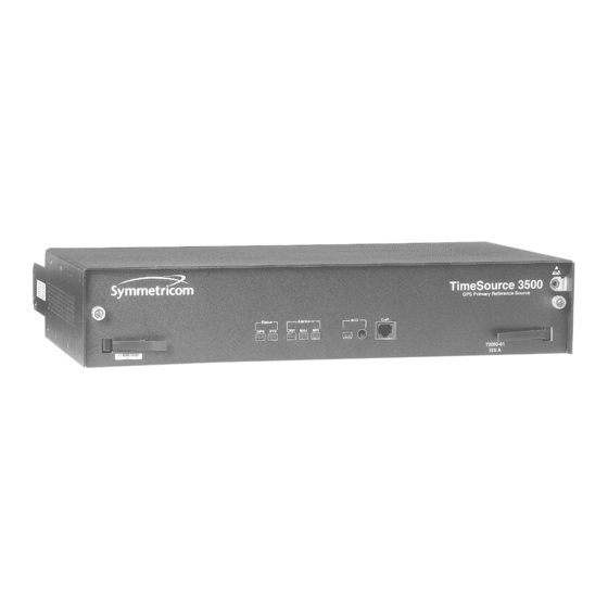
Physical Description The TimeSource 3500 consists of a shelf, a plug-in card, an antenna, cables, hardware, and software. Optional system configurations include eight additional T1 outputs, eight additional composite clock outputs, two IRIG-B TOD timing outputs, or eight mixed E1/T1 outputs. The shelf (Figure 1) occupies two rack mounting units (RU), and can be mounted in a 19 inch rack or a 23 inch rack. -
Page 23: Shelf
Figure 1. Shelf Air space (required for proper ventilation) 1.75 in 3.25 in. 17.25 in. TimeSource 3500 Description 097-72050-01 Issue 7: August 2003... -
Page 24: Shelf
Roof Antenna The roof antenna (Figure 2) is encased in weather-resistant plastic housing for outdoor installation, usually on a roof. A single coaxial cable carries signals and power between the antenna and the shelf. Figure 2. Roof Antenna 12.375 in. 1.75 in. -
Page 25: Mechanical Window Antenna
Mechanical Window Antenna The mechanical window antenna (Figure 3) may be attached to a window sill or wall, in any position that allows the antenna to be moved flush against the window. The antenna can be swung away from the window for window maintenance, and returned to its original position. -
Page 26: Self-Adhesive Window Antenna
Self-Adhesive Window Antenna The self-adhesive window antenna assembly (Figure 4) consists of the antenna and two pieces of self-stick hook-and-loop fabric fasteners (Velcro brand or equivalent). The hook-and-loop fabric attaches directly to a window. Coaxial cables carry signals and power between the antenna and the IF converter, and between the IF converter and the shelf. - Page 27 Wall Antenna The wall antenna (Figure 5) is mounted on the outside of a building wall. The antenna attaches magnetically to the mounting bracket. The cable from the antenna is routed through a hole drilled in the wall. Coaxial cables carry signals and power between the antenna and the IF converter, and between the IF converter and the shelf.
-
Page 28: Functional Description
Functional Description Overview Figure 6 shows the main functions of the TimeSource 3500. The center of the TimeSource 3500 is the BesTime Ensemble Timing Generator, which uses the BesTime algorithm to analyze the phase and frequency relationships, individually and collectively, of the timing sources. - Page 29 Figure 6. Block Diagram Alarm Alarms Interface COM Ports Micro- Ethernet Port Clock input & dc processor power to antenna Status Lamps Interface Antenna T1 Output A input Local T1 Output B BesTime Oscillator Ensemble Optional sources Timing 1 pps Output Generator T1 Span Clock...
-
Page 30: Antenna
Table A. Timing Source Characteristics Source Characteristic Local Oscillator Short term stability T1 Line Intermediate term stability GPS Signal Long term stability Antenna The antenna types include a roof antenna, mechanical window antenna, self-adhesive window antenna, or wall antenna. All antennas include a GPS receiver, amplifier, and intermediate- frequency (IF) downconverter. - Page 31 The zone of protection shall include the space not intruded by a rolling sphere having a radius of 150 ft (45.72 meters). Where the sphere is tangent to earth and resting against a strike termination device, all space in the vertical plane between the two points of contact and under the sphere shall be considered to be in the zone of protection.
-
Page 32: If Interface
If the wall antenna is installed outside the zone of protection, Symmetricom offers an outdoor and/or indoor lightning protector kits for these installations. Refer to Chapter 2, Engineering & Ordering, for more information on these kits. -
Page 33: Power Supply
Use of the Network Time Protocol (NTP) feature requires activation with a password. Activation is accomplished through receipt of a Network Time Protocol Activation Certificate from Symmetricom. This certificate contains the unit purchase order number, unit model number, unit activation date, unit serial number, and unit activation key. -
Page 34: Eight Mixed E1/T1 Outputs
BesTime algorithms in the BesTime Ensemble Timing Generator. The signals are analyzed for MDEV, TDEV, and other phase and frequency characteristics. The BesTime Ensemble Timing Generator uses mathematical models to analyze each clock. The ensemble algorithms use the comparisons and analyses to generate a highly stable timing signal, which uses the best qualities of all inputs. -
Page 35: Pps Output
Additional T1 Outputs (990-72050-02 Systems Only) This option provides eight additional T1 outputs. The outputs are available at the OPTIONS I/O wire-wrap pins on the rear panel. These outputs function the same as the standard T1 outputs. TOD Output The BesTime Ensemble Timing Generator provides the timing for the TOD timing signal available at the RJ-45 connector, which provides time code to devices compatible with NTP Type 4 or Cisco ASCII format. -
Page 36: 10 Mhz Output
10 MHz Output The BesTime Ensemble Timing Generator provides timing for the 10 MHz timing signal available at the 10 MHZ connector, which can be used for local cellular frequency or testing purposes. This signal is not squelched during an alarm. Composite Clock Outputs (990-72050-03 Systems Only) This option provides eight composite clock signals. -
Page 37: Autonomous Messages
Four ports (5001, 5002, 5003, and 5004) are configured to act as though a serial-port communication terminal were connected to them. These ports communicate TL1 commands, responses and autonomous messages. Two additional ports communicate with Element Managers, which may have NMS, OSMF, or similar software. An Element Manager establishes a connection with one port (5551) for TL1 commands and responses. -
Page 38: Alarm Programmability
Figure 8 shows a TimeSource 3500 Passthrough setup. Figure 8. TimeSource 3500 Passthrough Function DCDPASSTHRU User port (any port) Straight cable DCD-5X TS-3500 DCDUSERPORT COM 1, 2, 3 IP: 5001 - 5004 COM 1, 2, COM 1 or 2 (COM 1 is or 3 DB-25 and COM 2 is RJ-45) -
Page 39: Startup
Startup When the TimeSource starts up, the CRIT lamp lights. The CRIT lamp remains on for approximately 50 seconds to 60 seconds and then shuts off. During startup, the TimeSource performs several self-tests to verify the integrity of the hardware and software. Neither communication nor outputs are possible at this time, and the CRIT lamp is switched on. -
Page 40: Bridging/Holdover Behavior
outputs are enabled using the TL1 command (ED-EQPT::TS3500:ctag:::ALMCOND=ALW;) they may not be within the PRS mask. In case the system is not able to acquire sufficient number of satellites and/or discipline the oscillator within 2 hours, the event escalates into a Non Service Affecting Minor alarm. - Page 41 The system allows the user to set various parameters for GPS error, Holdover error, and SPAN error conditions. These parameters are: • Initial Severity • Initial Service Affecting state • Integration Time • Final Severity • Final Service Affecting state The system also allows the user to set a parameter to define how outputs should behave in an alarm condition.
-
Page 42: Time Figure Of Merit
Time Figure of Merit Time Figure of Merit (TFOM) is a moving 24 hour measurement reported in nanosecond (ns) against an ideal model. TFOM has a frequency component used to measure GPS wander caused by multipath and a time loop component used to measure long term oscillator wander. - Page 43 ground. Wall/window installations also require the manual input of location data, creating the potential for errors and the need to detect these errors. The TimeSource has unique algorithms to account for, and defeat, the added multipath complications and location data entry error possibilities of wall/window antenna installations.
- Page 44 • New building construction • Variations in the day-to-day temperature of the CO TimeSource 3500 Description 097-72050-01 Issue 7: August 2003...
- Page 45 Chapter Engineering & Ordering This chapter provides information to assist in planning the installation and ordering a system appropriate for a specific site.
-
Page 46: Antenna Guidelines
Antenna Guidelines Perform a site survey as described in Procedure A before ordering the system. Use the guidelines and considerations in the Roof/ Window/Wall Antenna Location and Cabling Guidelines section and the Shelf Considerations section. TimeSource 3500 Engineering & Ordering 097-72050-01 Issue 7: August 2003... -
Page 47: A. Site Survey
Procedure A. Site Survey Step Action Determine the shelf location. Determine the best location for mounting the antenna (less than 1,000 ft of cable from the shelf). Use the guidelines and considerations in the Roof Antenna Location and Cabling Guidelines section. If a roof-mounted antenna is installed, determine the location of the grounding point for the lightning suppressor, then determine the location of the lightning suppressor. -
Page 48: Guidelines
Roof Antenna Location and Cabling Guidelines DANGER: Do not select an antenna location that could be an electrical or physical hazard to work persons or equipment. Avoid proximity to all high-voltage sources. Mount in an easily maintainable location. The ideal roof antenna location provides a clear, unobstructed view of the sky from the zenith to the horizon line, and 360 degrees around the horizon. -
Page 49: Antenna Field Of View
Figure 9. Antenna Field of View Antenna position Obstructions toward the pole Antenna if possible field of view 10° 10° Mask angle* Mask angle* Horizon Equator Pole * An angle of 10° masks objects up to about 3.5 ft above the 10°... - Page 50 Figure 10. Antenna Location Examples Building Antenna tower antenna antenna Water location Roof location tower (Note 2) structure (Note 1) Tree Antenna tower Location A Location B Notes: 1. Place the antenna high enough on the tower that obstructions are below the mask angle; mount the antenna more than 3 feet away from the tower, and far below the interference of the antennas at the top of the tower.
- Page 51 frequency. A transmitting antenna may cause the GPS antenna to become overloaded and reduce its reception capabilities. The minimum horizontal distance from other receiving antennas is 3 feet. To reduce multipath signal distortions, the minimum horizontal distance from vertical reflective structures (e.g., heating ducts, equipment housings, etc.) is twice the height of the structure, and no less than 10 feet (Figure 11).
- Page 52 (twice the 8 ft height) (10 ft minimum) Pipe clamped to wall Cable entry into building Building Wall Note: This is an example only. Not all parts are available from Symmetricom. TimeSource 3500 Engineering & Ordering 097-72050-01 Issue 7: August 2003...
-
Page 53: Roof Antenna Earth Ground Location Guidelines
Roof Antenna Earth Ground Location Guidelines The roof ring ground system, a Central Office grounding plate, and building structural steel are examples of valid earth ground points. If the mounting plate cannot be bolted to a valid earth ground, or if the mounting plate is to be installed in a nonmetallic junction box, bolt the mounting plate to a point within 15 feet of the valid earth ground. -
Page 54: Roof Antenna Cable Choices
The antenna assembly uses the same coaxial cable for power and antenna signals. The length of cable is determined by circumstances of the installation and site. Symmetricom offers RG-59/U plenum-rated coaxial cable (20 AWG [0.812 mm], 75 ohm coaxial) with male TNC connectors attached, in the following lengths: •... - Page 55 The following items, which must be ordered separately, are available for this type of installation: • TNC connector kit (093-72010-98) includes: - TNC connectors for RG-59/U cables (8) - Rubber boots (8) - TNC adapter connectors (2) • TNC crimp tool (154-00023-01) TimeSource 3500 Engineering &...
-
Page 56: Location Guidelines
Window and Wall Antenna Location Guidelines When selecting a window or wall in which to install the antenna, select the window or wall which has the maximum unobstructed view of the sky. Do not select a window or wall which has the view of the sky obstructed by trees, buildings, or towers. -
Page 57: Antenna Mask Angle
Figure 12. Antenna Mask Angle 10° mask angle* TimeSource 3500 Note: TimeSource 3500 does Antenna 3.5 ft not detect satellites in the masked area. 20 ft *An angle of 10° masks objects up to about 3.5 ft above the horizon at 20 ft from the antenna. -
Page 58: Cable Choices
Window and Wall Antenna Cable Choices A window or wall antenna includes an attached coaxial cable terminating in a male SMA connector. A separate cable is required to connect the IF converter to the TimeSource 3500 shelf. Two types of plenum-rated cable are available. The cables with longer length capabilities (060-72010-xx) are RG-59/U (20 AWG [0.812 mm], 75 ohm coaxial) with male TNC connectors attached to each end. - Page 59 The more flexible cables (060-72050-xx) are Mini RG-59/U (20 AWG [0.812 mm], 75 ohm coaxial) with male TNC connectors attached to each end. Assembled cables are available in the following lengths: • 50 feet (060-72050-05) • 100 feet (060-72050-10) • 200 feet (060-72050-20) •...
- Page 60 IRIG-B TOD (990-72050-05 System Only) If using the IRIG-B TOD outputs (990-72050-05 TimeSource 3500 System), right-angle BNC connectors are provided to prevent small radius turns in the IRIG-B TOD cables. The right-angle BNC connectors may be attached to the IRIG-B BNC adapter (also provided) BNC connectors, to direct the cables from the shelf as desired.
-
Page 61: Rj-422–To–Rs-232 Tod Converter
RJ-422–to–RS-232 TOD Converter If using time-of-day (TOD), and the device receiving the time code accepts an RS-232 signal instead of an RS-422 signal (for example, a Cisco router), an RJ-422–to–RJ-232 TOD Converter Kit is required (ordered separately, part number 093-72000-98). The RJ-422–to–RJ-232 TOD Converter Kit consists of a mounting plate with a female RJ-45 connector, a female DB-25 connector, a TOD converter, and two screws. -
Page 62: Shelf Considerations
Shelf Considerations The TimeSource 3500 Shelf can be mounted in a 19 inch rack or a 23 inch rack. The shelf is shipped with supplied mounting ears positioned for flush mounting on a 23 inch rack. Attach the mounting ears, as shown in Figure 13, for flush mounting or 5 inch offset mounting. -
Page 63: Systems
Systems The TimeSource 3500 Systems available are listed below. The antenna must be ordered separately. TimeSource 3500 Engineering & Ordering 097-72050-01 Issue 7: August 2003... -
Page 64: Standard System (Two T1 Outputs)
Standard System (Two T1 Outputs) This system (990-72050-01) includes: • TimeSource 3000 Shelf (090-72000-01) • TimeSource 3500 card (090-72050-01) • Hardware kit (093-72050-87) • System software compact disc (CD) (992-72050-xx) Version 1.05.04 or higher • TimeScan Craft (keyless version) software CD (992-46750-xx) Version 7.2.0 or higher TimeSource 3500 Engineering &... -
Page 65: With Eight Additional T1 Outputs
With Eight Additional T1 Outputs This system (990-72050-02) includes: • TimeSource 3000 Shelf (090-72000-01) • TimeSource 3500 card with additional T1 outputs (090-72050-02) • Hardware kit (093-72050-87) • System software CD (992-72050-xx) Version 1.05.04 or higher • TimeScan Craft (keyless version) software CD (992-46750-xx) Version 7.2.0 or higher TimeSource 3500 Engineering &... -
Page 66: E1/T1 Outputs
With Eight Additional Mixed E1/T1 Outputs This system (990-72050-06) includes: • TimeSource 3000 Shelf (090-72000-01) • TimeSource 3500 card with mixed E1/T1 outputs (090-72050-06) • Hardware kit (093-72050-87) • System software CD (992-72050-xx) Version 1.05.04 or higher • TimeScan Craft (keyless version) software CD (992-46750-xx) Version 7.2.0 or higher TimeSource 3500 Engineering &... -
Page 67: With Eight Additional Mixed T1/Cck Outputs
With Eight Additional Mixed T1/CCK Outputs This system (990-72050-07) includes: • TimeSource 3000 Shelf (090-72000-01) • TimeSource 3500 card with mixed T1/CCK outputs (090-72050-07) • Hardware kit (093-72050-87) • System software CD (992-72050-xx) Version 1.06.02 or higher • TimeScan Craft (keyless version) software CD (992-46750-xx) Version 7.2.0 or higher TimeSource 3500 Engineering &... -
Page 68: Outputs
With Eight Composite Clock Outputs This system (990-72050-03) includes: • TimeSource 3000 Shelf (090-72000-01) • TimeSource 3500 card with composite clock outputs (090-72050-03) • Hardware kit (093-72050-87) • System software CD (992-72050-xx) Version 1.05.04 or higher • TimeScan Craft (keyless version) software CD (992-46750-xx) Version 7.2.0 or higher TimeSource 3500 Engineering &... -
Page 69: With Two Irig-B Tod Outputs
With Two IRIG-B TOD Outputs This system (990-72050-05) includes: • TimeSource 3000 Shelf (090-72000-01) • TimeSource 3500 card with IRIG-B TOD outputs (090-72050-05) • IRIG-B BNC adapter board (090-72100-06) • Two right-angle BNC connectors (121-00530-01) • Hardware kit (093-72050-87) • System software CD (992-72050-xx) Version 1.05.04 or higher •... -
Page 70: Antennas
Antennas The antennas available are listed below. A TimeSource 3500 System must be ordered separately. TimeSource 3500 Engineering & Ordering 097-72050-01 Issue 7: August 2003... -
Page 71: Roof Antenna
Roof Antenna This antenna kit (990-72050-96) includes: • IF antenna assembly (090-72010-97) • Rooftop antenna installation kit (093-72050-96) includes: Antenna cable bracket kit (070-00377-01) Mounting bracket for surge suppressor (070-00300-02) Surge suppressor (143-00018-01) Miscellaneous installation parts TimeSource 3500 Engineering & Ordering 097-72050-01 Issue 7: August 2003... -
Page 72: Mechanical Window Antenna
Mechanical Window Antenna This antenna kit (990-72050-97) comes as a fully assembled antenna with the following major components: • Antenna, with cable and SMA connector attached (090-72050-90) • IF converter (090-72050-97) • Mechanical chassis (074-72050-97) TimeSource 3500 Engineering & Ordering 097-72050-01 Issue 7: August 2003... -
Page 73: Self-Adhesive Window Antenna
Self-Adhesive Window Antenna This antenna kit (990-72050-98) includes: • Antenna (090-71010-87) • IF converter (090-72050-97) • Self-adhesive window antenna installation kit (093-72050-98) includes: RG316 cable, 10 feet (060-00062-01) Cable tie mounts (128-00302-02) and cable ties (128-00500-05) TimeSource 3500 Engineering & Ordering 097-72050-01 Issue 7: August 2003... -
Page 74: Wall Antenna
Wall Antenna Order one of these two available wall antenna kits based on the users antenna cable length installation requirements: This antenna kit (990-72050-99) includes: • IF converter (090-72050-97) • Wall antenna kit (093-72050-99) includes: Antenna, with 19 feet of cable and SMA connector attached (112-00013-01) Antenna mounting bracket (070-00383-02) Clamp tie mounts (128-00302-02) and... - Page 75 Wall Antenna (cont’d) • Wall antenna indoor lightning suppressor kit (093-72050-94) (optional) includes: Mounting bracket (070-00300-02) Surge protector (143-00018-01) RG59 cable, 2 feet (060-72010-92) • Wall antenna L1 outdoor lightning suppressor kit (093- 72050-93) (optional) includes: Mounting bracket (070-00300-03) Surge protector (143-00018-02) RG316 cable, 10 feet, SMA(m)-SMA(m) (060-00062-01) TimeSource 3500 Engineering &...
-
Page 76: User-Supplied Tools And Materials
User-Supplied Tools and Materials Ensure that the user-supplied tools and materials listed below are on hand for installation, as applicable. TimeSource 3500 Engineering & Ordering 097-72050-01 Issue 7: August 2003... -
Page 77: For Roof Antenna Installation
For Roof Antenna Installation • 1 inch diameter galvanized metal pipe, used as a mast to mount the antenna. Mast should be long enough to position the antenna above any metal object on the roof. • Screws to attach the lightning suppressor mounting plate. •... -
Page 78: For Mechanical Window Antenna Installation
For Mechanical Window Antenna Installation • Drill with bit of appropriate size and type to make pilot holes for the mounting screws • 2 screws of appropriate size and type to attach the foot of the mechanical chassis to a window sill or wall near a window. •... -
Page 79: For Self-Adhesive Window Antenna Installation
For Self-Adhesive Window Antenna Installation • Drill with bit of appropriate size and type to make pilot holes for the mounting screws • 4 screws of appropriate size and type to attach the IF converter to a wall or other mounting surface. •... -
Page 80: For Wall Antenna Installation
For Wall Antenna Installation • Ladder, or safe method of reaching the antenna location on the exterior wall • Drill with bits of appropriate size and type to make pilot holes for the antenna mounting bracket screws, and to make a hole through the wall for the antenna cable •... -
Page 81: For Shelf Installation
For Shelf Installation • A Phillips-head screwdriver for installing the TimeSource 3500 Shelf in a rack • Four screws to mount the shelf in a rack TimeSource 3500 Engineering & Ordering 097-72050-01 Issue 7: August 2003... -
Page 82: Outputs, Power, And Miscellaneous
Outputs, Power, and Miscellaneous • RG-58 coaxial cable for 1 PPS, 10 MHZ outputs • Ethernet 10BaseT cable for Ethernet port • Category 5 four-pair RS-422 cable, with RJ-45 connector for the TOD output, RS-422–to–RS-232 TOD converter • RS-232 cable with DB-25 connector for the RS-422–to– RS-232 TOD converter •... - Page 83 This page intentionally left blank. TimeSource 3500 Engineering & Ordering 097-72050-01 Issue 7: August 2003...
- Page 84 TimeSource 3500 Engineering & Ordering 097-72050-01 Issue 7: August 2003...
- Page 85 Installation Chapter This chapter is the sequential order of procedures for installation and power-...
-
Page 86: Installation
Contact Customer Service if additional packaging is needed. Unpack equipment carefully; check for completeness against the purchase order. Notify Symmetricom if items are missing. Inspect equipment for shipping damage, including bent or loose hardware, and broken connectors. -
Page 87: Antenna
Antenna Roof Antenna Installation procedures are to follow local company procedures and the Installation Job Specification. Prior to installing the antenna, the site, antenna location, lightning suppressor location, lightning suppressor grounding point, cable route, and all other details should have been planned. To install the antenna, refer to Figure 14 and perform Procedure B. - Page 88 Figure 14. Roof Antenna-to-Shelf Cabling Antenna 090-72010-97 Antenna Mounting Hardware (070-00377-01) RG-59/U Cable TNC Connector (060-72010-xx) (Attached to cable) (See Note 2) Lightning Suppressor (143-00018-01) TNC Connector and Mounting Bracket (Attached (070-00300-02) to cable) Valid earth ground TNC Connector (See Note 1) (Attached to cable) RG-59/U Cable...
-
Page 89: Screws
Procedure B. Roof Antenna Mounting and Cable Connection Step Procedure Attach the antenna mounting bracket to a pipe (1 in. diameter) or a wood post. • If mounting the bracket to a pipe, slide the two V-bolts over the pipe, and through the mounting bracket slots;... - Page 90 Procedure B. Roof Antenna Mounting and Cable Connection (cont’d) Step Procedure Slide the antenna bolts through the holes in the mounting bracket, then attach the antenna to the bracket, using the provided three nuts and three lockwashers. Antenna (±5° of vertical) 090-72010-97 Antenna Bolts (3) Lock washers (3)
- Page 91 Procedure B. Roof Antenna Mounting and Cable Connection (cont’d) Step Procedure Slide the longer bolt of the lightning suppressor through the D-hole, and attach with a nut and a washer (provided). KEPS nut (2) 6 AWG (4.115 mm) ground wire Washer D-hole Lightningsuppressor...
- Page 92 Procedure B. Roof Antenna Mounting and Cable Connection (cont’d) Step Procedure If the lightning suppressor was not mounted directly to a valid earth ground, crimp a length of 6 AWG (4.115 mm) ground cable to the two-hole terminal, slide the terminal over two of the three threaded posts on the lightning suppressor mounting plate, and attach the terminal to the mounting plate with two KEPS nuts.
-
Page 93: Mechanical Window Antenna
Mechanical Window Antenna Installation procedures are to follow local company procedures and the Installation Job Specification. Prior to installing the antenna, the site, antenna location, cable route, and all other details should have been planned. For best results, choose a window facing the equator (facing south in the northern hemisphere, facing north in the southern hemisphere), and with the fewest obstructions of the sky. -
Page 94: Cabling
Figure 15. Mechanical Window Antenna-to-Shelf Cabling Antenna Antenna Assembly Components of 990-72050-97 990-72050-97 Antenna-to-IF cable antenna assembly IF Converter TNC Connector IF-to-shelf cable (on IF converter) RG-59/U Cable TNC Connector 060-72010-xx (Attached to cable) (10 feet to 1,000 feet) or Mini RG-59 Cable 060-72050-xx (50 feet to 500 feet) -
Page 95: C. Mechanical Window Antenna Mounting And Cable Connection
Prerequisite: Observe all guidelines, considerations, Dangers, Warnings, Cautions, and Notes in the Engineering and Ordering chapter. Symmetricom Parts: • Mechanical Window Antenna (990-72050-97) • A length of RG-59/U plenum-rated coaxial cable (060-72010-xx), or • A length of Mini RG-59/U plenum-rated coaxial cable (060-72050-xx) User-Supplied Materials: •... -
Page 96: Antenna
Figure 16. Attaching the Mechanical Window Antenna Use 2 user-supplied screws to attach to wall or window sill Figure 17. Mechanical Window Antenna Pivot Screws Place the antenna against the window by moving the chassis on these pivots. Tighten these pivot screws to lock antenna position. -
Page 97: Self-Adhesive Window Antenna
Self-Adhesive Window Antenna Prior to installing the antenna, the site, antenna location, cable route, and all other details should have been planned. Installation procedures are to follow local company procedures and the Installation Job Specification. For best results, choose a window facing the equator (facing south in the northern hemisphere, facing north in the southern hemisphere), and with the fewest obstructions of the sky. -
Page 98: D. Self-Adhesive Window Antenna Mounting And Cable Connection
Prerequisite: Observe all guidelines, considerations, Dangers, Warnings, Cautions, and Notes in the Engineering and Ordering chapter. Symmetricom Parts: • Self-Adhesive Window Antenna kit (990-72050-98) • A length of RG-59/U plenum-rated coaxial cable (060-72010-xx), or • A length of Mini RG-59/U plenum-rated coaxial cable (060-72050-xx) User-Supplied Materials: •... -
Page 99: Attaching The Self-Adhesive Window Antenna To A Window
Procedure D. Self-Adhesive Window Antenna Mounting and Cable Connection (cont’d) Step Procedure Check all connections for tightness to prevent intermittent operation. End of Procedure Figure 19. Attaching the Self-Adhesive Window Antenna to a Window Stick the antenna to the Attach the hook-and- window. -
Page 100: Wall Antenna
Wall Antenna Prior to installing the antenna, the site, antenna location, cable route, and all other details should have been planned. Installation procedures are to follow local company procedures and the Installation Job Specification. For best results, choose a wall facing the equator (facing south in the northern hemisphere, facing north in the southern hemisphere), and with the fewest obstructions of the sky. -
Page 101: Wall Antenna Outdoor Lightning
Prerequisite: Observe all guidelines, considerations, Dangers, Warnings, Cautions, and Notes in the Engineering and Ordering chapter. Symmetricom Parts: • Wall Antenna (990-72050-95 with 6’ antenna cable or 990-72050-99 with 19’ antenna cable) • Wall Antenna Indoor Lightning Suppressor Kit (093-72050-94) (optional) •... - Page 102 Procedure E. Wall Antenna Installation (cont’d) Step Action Drill two pilot holes for the user-supplied screws or bolts that attach the mounting bracket to the outside wall. Using two screws or bolts, mount the antenna bracket assembly to the outside wall.
- Page 103 Procedure E. Wall Antenna Installation (cont’d) Step Action Slide the longer bolt of the lightning suppressor through the D-hole, and attach with a nut and a washer (provided). KEPS nut (2) 6 AWG (4.115 mm) ground wire Washer D-hole Lightningsuppressor Mounting plate Hole for mounting bolt (2) Cable connector (2)
- Page 104 Procedure E. Wall Antenna Installation (cont’d) Step Action If the optional Wall Antenna Outdoor Lighting Suppressor Kit (093-72050-93) is not required, the Wall Antenna Installation in Procedure E is completed here. Otherwise, proceed with the next step. Mount the outdoor lightning suppressor mounting bracket to the outside wall shown in Figure 24.
- Page 105 Procedure E. Wall Antenna Installation (cont’d) Step Action Route the wall antenna cable to the antenna side of the outdoor lightning suppressor and connect the cable. Route the RG 316 10 ft cable provided from the outdoor lightning suppressor through the wall to the IF converter and connect both ends. Connect the user provided RG-59 cable from the IF converter to the TimeSource 3500 shelf.
-
Page 106: Wall Antenna Mounting
Figure 23. Wall Antenna Mounting Holes for bolts/screws Mounting bracket Antenna cable Hole for cable Antenna Wall Drip loop Building interior Building exteri TimeSource 3500 Installation 097-72050-01 Issue 7: August 2003... -
Page 107: Suppressor Mounting
Figure 24 Wall Antenna Outdoor Lightning Suppressor Mounting Wall Wall Mounting Mounting bracket bracket Hole for cable Hole for cable RG-316 Cable (10 feet) RG-316 Cable (10 feet) Outdoor Lightning Outdoor Lightning 060-00062-01 060-00062-01 Suppressor Suppressor Antenna Antenna IF Converter IF Converter Antenna cable Antenna cable... -
Page 108: Shelf
Shelf Rack Mounting The shelf is shipped with the ears positioned for flush mounting in a 23 inch rack (Figure 25B). The ears can be positioned in the front of the shelf for flush mounting (Figure 25A, and Figure 25B), or in the middle of the shelf for 5 inch offset mounting (Figure 25C and Figure 25D). -
Page 109: Power And Signal Cabling
Power and Signal Cabling Warning: The circuitry on the plug-in circuit board is subject to electrostatic discharge (ESD) damage. Be sure to wear an ESD wrist strap when making connections to the rear panel. Failure to observe this warning may result in equipment damage. -
Page 110: Rear Panel Connectors
Figure 26. Rear Panel Connectors Optional T1, E1/T1, Antenna Office 1 pps 10 MHz T1/CCK, Composite Clock, Input Alarms Port 1 Output Output or IRIG-B Outputs Time of T1 Reference T1 Synchronization Battery A Inputs A & B Outputs A & B &... -
Page 111: Frame Ground
Frame Ground Frame ground connections are made on power terminal blocks TB1 and TB2. Refer to Figure 26 for the location of the terminals on the rear of the shelf, and refer to Figure 28 for the terminal connections. Figure 28. Battery Connections –48V –48V A. - Page 112 Make the ground connection, following one of the methods described below, depending on whether a ground rod is installed: With ground rod Solder the frame ground connection to the 6 AWG (4.115 mm) frame ground rod run vertically on each side of the rack. Two methods are acceptable: •...
-
Page 113: Power
Power Warning: This equipment is intended for installation in a restricted access location. Power source protective fusing must be provided as part of the installation. Caution: Do not apply power to the TimeSource 3500 before instructed in this procedure. Before connecting the power cables to the TimeSource 3500, ensure the fuses are removed from the fuse panel that supplies power to the power cables. -
Page 114: Alarms Output
Alarms Output Connect the TimeSource 3500 alarms to the office alarm panel at the critical (CR), major (MJ), and minor (MN) wire-wrap pins. See Figure 26 for the location of the alarm pins, and Figure 29 for the connections. Connect at the upper group of pins (AUD) for audible alarms and at the lower group of pins (VIS) for visible alarms. -
Page 115: Additional T1 Outputs
Additional T1 Outputs (990-72050-02 System Only) Connect up to eight optional T1 outputs at the OPTIONS I/O wire- wrap pins. See Figure 26 for the connector location, and Figure 30 for the connections. Note: The shield pin is capacitively coupled to ground, therefore, the shield must be connected at the source end. - Page 116 Mixed T1/CCK Outputs (990-72050-07 System Only) Connect up to eight optional mixed T1/CCK outputs at the OPTIONS I/O wire-wrap pins. Refer to Figure 26 for the connector location and Figure 30 for the connections. Composite Clock Outputs (990-72050-03 System Only) Connect up to eight optional composite clock outputs at the OPTIONS I/O wire-wrap pins.
-
Page 117: Irig-B Tod Bnc Output Connections
Figure 31. IRIG-B TOD BNC Output Connections Screws (4 places) Output 1 Output 2 Procedure F. IRIG-B TOD Output Installation Step Procedure Position the IRIG-B adapter onto the rear of the shelf so that the OPTIONS I/O wire-wrap pins project through holes in the adapter card. Secure the adapter onto the shelf, using the four screws integral to the adapter (see Figure 31). -
Page 118: Pps Output
1 PPS Output Connect a user-supplied RG-58 coaxial cable from the connector labeled TTL PPS to the equipment that will use the 1 pulse-per- second TTL output signal. See Figure 26 for the connector location. 10 MHz Output Connect a user-supplied RG-58 coaxial cable from the connector labeled 10 MHz to the equipment that will use the 10 MHz output signal. -
Page 119: Ethernet 10Base-T Rj-45 Connector Pinouts
Ethernet Connect a user-supplied Ethernet cable from the network to the 10base-T Ethernet connector labeled E-NET. See Figure 26 for the connector location, and Table B for the connector pinouts. Table B. Ethernet 10base-T RJ-45 Connector Pinouts Signal Abbreviation Direction Transmit data + TXD + From TimeSource 3500... -
Page 120: Time Of Day Output
Time of Day Output Connect a time of day (TOD) output at the female RJ-45 connector labeled TOD. See Figure 26 for the connector location, and Table C for the connector pinouts. Table C. TOD Connector Pinouts Signal Abbreviation Direction 1 pps A TOD PPS + From TimeSource 3500... -
Page 121: G. Rs-422–To–Rs-232 Tod Converter Installation
Procedure G. RS-422–to–RS-232 TOD Converter Installation Step Procedure Secure the provided mounting plate to the RS-422–to–RS-232 TOD converter, using the two provided screws. The plate may be attached to the top or front of the converter, depending on the desired surface (for example, a rack or cabinet) to which the converter will be mounted (see Figure 32). -
Page 122: Rs-422-To-Rs-232 Tod Converter Mounting Plate
Figure 32. RS-422–to–RS-232 TOD Converter Mounting Plate Screws Mounting plate Mounting plate (supplied) attached to top attached to front of converter of converter Screws Converter Converter (supplied) Figure 33. RS-422–to–RS-232 TOD Converter Connections DB-25 Connector (Female) RJ-45 Connector To device (Female) receiving 50 ft... -
Page 123: Converter Db-25 Connector Pinouts
Table D. Converter DB-25 Connector Pinouts Signal Frame ground Data output (RS-232) 1 pps (RS-232) Signal ground Note: Pins not listed are reserved for future use. TimeSource 3500 Installation 097-72050-01 Issue 7: August 2003... - Page 124 T1 Reference Inputs Warning: Because the T1 input circuits do not provide lightning protection, do not connect the T1 input line directly to an outside facility. Failure to observe this warning may result in equipment damage. T1 reference sources, traceable to an independent Stratum 1 source, can be connected to further increase holdover stability, or to be monitored by the TimeSource 3500.
- Page 125 T1 Synchronization Outputs Warning: Because the T1 output circuits do not provide lightning protection, do not connect the T1 output line directly to an outside facility. Failure to observe this warning may result in equipment damage. Connect the T1 synchronization outputs at the wire-wrap pins labeled T1 OUT A and T1 OUT B.
-
Page 126: Com1 Pinouts
Communication Port 1 To provide an RS-232 link for TL1 command access to the TimeSource 3500, connect to port 1 at the female 25-pin D connector labeled COM1. See Figure 26 for the location of the connector. See Table E for the connector pinouts. Note: The COM1 connector transmits data on pin 2, and receives data on pin 3. - Page 127 Communication Port 2 To provide an RS-232 link for TL1 command access to the TimeSource 3500, connect to port 2 at the female RJ-45 connector labeled COM2. See Figure 26 for the location of the connector, and Table F for the connector pinouts. Note: The COM2 connector transmits data on pin 2, and receives data on pin 3.
-
Page 128: Craft Pinouts
Craft Port To provide an RS-232 link for TL1 command access to the TimeSource 3500, connect to the craft port at the female RJ-45 connector labeled Craft on the front panel. A Craft-port-to-PC cable is supplied with the TimeSource 3500 for making this connection. -
Page 129: Power-Up
Power-Up To power the TimeSource 3500, follow the steps in Procedure H. Before starting this procedure, be sure the antenna, shelf, and all connections appropriate for this installation have been installed, and that the host computer is set to communicate with the TimeSource 3500. - Page 130 Procedure H. Power-Up (cont’d) Step Procedure On the computer connected to the TimeSource 3500, connect the computer communication port to the COM1, COM2, or Craft port on the TimeSource 3500. A craft port-to-PC communication cable is provided in the hardware kit for this purpose. Ensure that the TimeSource 3500 plug-in card is not installed in the shelf.
- Page 131 Procedure H. Power-Up (cont’d) Step Procedure Install the battery source fuse(s) in the rack fuse bay that supplies power to the TimeSource 3500. The TimeSource 3500 enters its warm-up mode after approximately 60 s when power is applied. During the warm-up period, the following conditions exist: •...
- Page 132 Procedure H. Power-Up (cont’d) Step Procedure Skip this step if the current unit is equipped with a roof antenna. Use the Edit Equipment command to change the antenna locating mode to manual and to enter the latitude, longitude, and altitude. In manual mode, the survey process used to determine the antenna’s exact position starts with this information.
- Page 133 Procedure H. Power-Up (cont’d) Step Procedure Notes: (cont’d) (cont’d) 2. Latitude, longitude, and altitude data can be obtained through the use of a GPS hand-held receiver (user supplied). Location mapping software is also available for personal computers, which can be used to obtain latitude and longitude.
- Page 134 Procedure H. Power-Up (cont’d) Step Procedure If UTC time is not desired, skip to Step19. Use the Edit Date command to set the system for UTC time. ED-DAT:::<ctag>::yyyy-mm-dd:MODE=UTC; yyyy= year (yyyy = 1998 to 2096) month (mm = 01 to 12) day (dd = 01 to 31) Example command to set UTC time: ED-DAT:::123::2000-06-15:MODE=UTC;...
- Page 135 Procedure H. Power-Up (cont’d) Step Procedure Use the Edit Equipment command to set the output signal framing format for the two standard T1 outputs, and set the mode for each T1 output during an alarm. ED-EQPT::T1-a:<ctag>:::FRAMING=b,ALMOUT=c; a= T1 output (a = A or B) b= framing format (b = ESF or D4) c= T1 output during alarm (c = AIS, SQUELCH, or SSM) (for SSM, framing format must be ESF)
- Page 136 Procedure H. Power-Up (cont’d) Step Procedure If not using Ethernet, go to Step 28. Use the Edit Equipment command while connected to COM1, COM2, or the CRAFT port to set the IP address, subnetwork mask, and gateway address for the current TimeSource 3500 unit, as required for proper operation in the managed element network.
- Page 137 Procedure H. Power-Up (cont’d) Step Procedure Ports 5001, 5002, 5003 and 5004 on the TimeSource 3500 are used as though they were serial TL1 communication ports. The following values are set at the factory and appear at reset: MONMSG=INH (monitors only the current port for messages) KEEPALIVE=0 (does not send a COMPLD message to keep connection open) ENDOFTEXT=0 (does not include an end-of-text code with a TL1 message) ECHO=ALW (echoes characters back to the sending terminal)
- Page 138 Procedure H. Power-Up (cont’d) Step Procedure If not using an Element Manager, skip to Step 28. If not using a separate port to send autonomous messages to an Element Manager, skip to Step 27. Use the Edit Equipment command to set the IP address and port address of the Element Manager.
- Page 139 Procedure H. Power-Up (cont’d) Step Procedure Use the Edit Communications command to set the communications parameters of port 5551. An Element Manager connects to port 5551 for TL1 command and response messages. The following values for port 5551 are set at the factory and appear at reset: MONMSG=INH (monitors only the current port for messages) KEEPALIVE=0 (does not send a COMPLD message to keep connection open)
- Page 140 Procedure H. Power-Up (cont’d) Step Procedure If the results of Step 19 indicate the antenna cable delay and elevation mask are set as desired, skip to Step 29. Use the Edit Equipment command to set the length of cable between the antenna and the TimeSource 3500 Shelf. This number should have been recorded during installation.
- Page 141 Procedure H. Power-Up (cont’d) Step Procedure Use the Copy Memory command to copy the database from volatile to nonvolatile memory within the TimeSource 3500. CPY-MEM:[tid]:TS3500:<ctag>::WKG,,AUX:DATA; Note: Although the database is automatically copied to nonvolatile memory once per hour, it is recommended that the Copy Memory command be executed each time the database is changed.
- Page 142 TimeWizard The TimeWizard Software Installation application was created to facilitate installing software upgrades for the TimeSource 3500. Procedure I shows how to install the TimeWizard application and how to use TimeWizard to download software upgrades. Procedure I. TimeWizard Installation and Operation Step Procedure Use this procedure to install the firmware in the TimeSource 3500 to configure the GPS...
- Page 143 Procedure I. TimeWizard Installation and Operation (cont’d) Step Procedure ⇒ ⇒ From the Windows desktop, click Start Programs TimeWizard to start the TimeWizard application. When TimeWizard starts, the “TimeWizard” main screen appears: The version of TimeWizard that is installed is indicated at the top right of the screen.
- Page 144 Procedure I. TimeWizard Installation and Operation (cont’d) Step Procedure If the user name or password of the TimeSource have been changed, enter the proper user name or password, otherwise, continue with the next step. To select the high-speed download option, in which the firmware download takes place at approximately 12 times the default speed of 9600 baud, select the Use High Speed (115K baud) check-box, then click the Next>>...
- Page 145 Procedure I. TimeWizard Installation and Operation (cont’d) Step Procedure Download the GPS.hex Firmware Note: If you are not downloading GPS.hex firmware, click the Next>> button again to advance to the “Download TS3000.hex” screen, then skip to Step 13. After the Next>> button is clicked in the previous step, the “Download GPS.hex” screen appears: The versions of the GPS.hex and TS3000.hex firmware that are currently installed in the TimeSource are shown in the GPS.hex Ver and TS3000.hex Ver...
- Page 146 Procedure I. TimeWizard Installation and Operation (cont’d) Step Procedure Click the ver Unknown button to open the Load GPS File dialog box: In the Load GPS File dialog box, navigate to the GPS.hex firmware file to be downloaded, then click the Open button. After the Open button is clicked, the message “Verifying version for C:\directory\Gps.hex (approx 10 secs)”...
- Page 147 The firmware download operation can be aborted at any time by clicking the Cancel button in the Download Progress dialog box. If the download fails for any reason, a screen appears with instructions to contact Symmetricom. If this happens, exit the application, check the cable connections, and restart TimeWizard. TimeSource 3500...
- Page 148 Procedure I. TimeWizard Installation and Operation (cont’d) Step Procedure After the Download Progress dialog box closes, continue to monitor the messages reported in the Commands area of the screen. After the firmware file finishes downloading from the PC to the TimeSource, the TimeSource requires more time to complete the firmware upgrade process.
- Page 149 The firmware download operation can be aborted at any time by clicking the Cancel button in the Download Progress dialog box. If the download fails for any reason, a screen appears with instructions to contact Symmetricom. If this happens, exit the application, check the cable connections, and restart TimeWizard. TimeSource 3500...
- Page 150 Procedure I. TimeWizard Installation and Operation (cont’d) Step Procedure After the Download Progress dialog box closes, continue to monitor the messages reported in the Commands area of the screen. After the firmware file finishes downloading from the PC to the TimeSource, the TimeSource requires more time to complete the firmware upgrade process.
- Page 151 Procedure I. TimeWizard Installation and Operation (cont’d) Step Procedure Verify the Firmware Versions The “Status Information” screen appears as follows: Verify that GPS.hex Ver and TS3000.hex Ver fields show that the correct versions of the GPS.hex and TS3000.hex firmware are now installed, then click the Next>>...
- Page 152 Procedure I. TimeWizard Installation and Operation (cont’d) Step Procedure Setup the Alarm Parameters When the Next>> button is clicked, the “Set the Alarm Parameters” screen appears: The Load and Save buttons allow a file to be generated that saves the alarm parameters in a file called TS3Kconf.sym as default.
- Page 153 Procedure I. TimeWizard Installation and Operation (cont’d) Step Procedure Choose the alarm parameters as desired. A description of each setting follows: Setting Description Severity 1 The initial severity of the alarm. Service Affecting 1 The initial service affecting status of the alarm condition. Time to Severity 2 If the Escalate Alarm check-box is selected, the alarm will be escalated to the severity and service affecting status...
- Page 154 Procedure I. TimeWizard Installation and Operation (cont’d) Step Procedure When the Next>> button is clicked, the “View the Alarm Parameters” screen appears: This screen confirms the alarm parameter settings from the previous screen. If the settings are correct, click the Next>> button to continue. If the settings are not correct, click the <<Back button to return to the “Set the Alarm Parameters”...
- Page 155 Procedure I. TimeWizard Installation and Operation (cont’d) Step Procedure Save the Log File, if Desired When the Next>> button is clicked, the “Exit Application” screen appears: This screen allows you to save the log file from the download operation, or exit TimeWizard without saving the log file.
- Page 156 Procedure I. TimeWizard Installation and Operation (cont’d) Step Procedure Select the Save Log File to check-box, then click the button that is adjacent to the check-box to invoke the Save Log File dialog box: In the Save Log File dialog box, navigate to the location to where the log file is to be stored, enter a name for the log file into the File Name field, then click the Save button to save the log file.
- Page 157 Factory-Set Values The parameter values initially set at the factory are shown in Table H. Table H. Parameter Factory Settings <aid> Parameter Setting TS3500 TOD=NONE ALMCOND=ALW IPNE=0.0.0.0 IPSUBNET=255.255.255.255 IPGATE=0.0.0.0 IPEM1=0.0.0.0 IPEM1PORT=0 IPEM2=0.0.0.0 IPEM2PORT=0 IPINACT=0 DCDPASSTHRU=INH DCDUSERPORT=2 TS3500 TIME=72-0 HOLDOVER SEV1=EV ALARM SEV2=MJ SAFF1=NSA...
- Page 158 Table H. Parameter Factory Settings (cont’d) <aid> Parameter Setting SPAN-A, ENSEMBLER=INH SPAN-B MONITOR=INH SSM=INH SPAN-A, SPAN-B TIME=24-0 LOS ALARM SEV1=EV SEV2=MN SAFF1=NSA SAFF2=NSA SPAN-A, SPAN-B TIME=24-0 AIS ALARM SEV1=EV SEV2=MN SAFF1=NSA SAFF2=NSA SPAN-A, SPAN-B TIME=24-0 ERROR ALARM SEV1=EV SEV2=MN SAFF1=NSA SAFF2=NSA T1-A, FRAMING=ESF...
- Page 159 Table H. Parameter Factory Settings (cont’d) <aid> Parameter Setting COM-5001, MONMSG=INH COM-5002, KEEPALIVE=0 COM-5003, ENDOF TEXT=00 COM-5004 ECHO=ALW COMPRI=ALW1 AUTOLOGOFF=20 SWCONTROL=INH COM-5551 MONMSG=INH KEEPALIVE=0 ENDOFTEXT=00 ECHO=INH COMPRI=ALW1 AUTOLOGOFF=20 SWCONTROL=INH OPT-1, OPT-2, FRAMING=ESF OPT-3, OPT-4, ALMOUT=AIS OPT-5, OPT-6, OPT-7, OPT-8 (990-72050-02, 990-72050-06, 990-72050-07 systems only)
- Page 160 TimeSource 3500 Installation 097-72050-01 Issue 7: August 2003...
- Page 161 TL1 Reference This chapter provides information for using the TL1 language. Chapter...
- Page 162 Conventions Uppercase letters in a command designate parameter values which must be entered as shown. Lowercase letters in a command are the parameter name, and the specific values that must be entered for the parameter. The Parameters section of this chapter describes the parameters and the values where a value is the same for all parameters.
- Page 163 indicates a space (used in the description of the response format, but not used in the command responses) – separates command code fields separates parameter blocks separates parameters within a block terminates a command, and causes execution " " encloses text to be parsed by a machine /* */ encloses comments for humans <...
-
Page 164: Command Format
Command Format A command consists of a command code of up to three fields separated by hyphens, followed by parameter blocks separated by colons. Figure 36 shows the command format. Parameter blocks consist of one or more parameters separated by commas. Parameter blocks may be null (contain no parameters), or contain one or more parameters. - Page 165 Response Format When a command is received and processed, a response is returned. All responses include a source identifier (<sid>), the date, the time, an M to indicate that it is a response to a command, and the correlation tag (<ctag>) that was entered with the command.
- Page 166 Parameters The parameters that may be used in commands, responses, and messages are defined in Table I. When a parameter uses the same values in every instance, those values are listed with the parameter in the table. When the context requires different values for a parameter, the value is listed with the parameter in the applicable commands, responses, and messages.
- Page 167 Table I. Parameter Definitions (cont’d) Parameter Definition <date> Date in the 8-digit form: yyyy-mm-dd (command) or yyyy:mm:dd (response or message), where yyyy is the year, mm is the month (01 to 12), and dd is the day of the month (01 to 31). For example, May 3, 2000 is 2000-05-03. <errcde>...
- Page 168 Table I. Parameter Definitions (cont’d) Parameter Definition <modifier> Equipment initiating the alarm or event message, which is one of the following: TS3500 = system software = GPS receiver software SPAN-x = T1 span input <mondat> Date of the performance monitoring data. <montm>...
- Page 169 Table I. Parameter Definitions (cont’d) Parameter Definition <sid> Source identifier of the equipment sending the message. The <sid> may contain a maximum of 20 characters (limited to letters, digits, and hyphens), and may begin with a letter. The <sid> is recommended to be the equipment’s CLLI code.
- Page 170 Table I. Parameter Definitions (cont’d) Parameter Definition <utc> Universal Coordinated Time (UTC) in the 6-digit form: hh-mm-ss, where hh is hours (00 to 23), mm is minutes (00 to 59), and ss is seconds (00 to 59). For example, 2:34 pm is 14-34-00. <vldty>...
- Page 171 Autonomous Messages Autonomous messages are sent out when an alarm or event occurs. Two types of autonomous messages are used: • Report Alarm: reports alarms • Report Event: reports events that are not alarms, or that have not yet become alarms Autonomous messages are listed on the following pages.
-
Page 172: Report Alarm
Report Alarm This autonomous message appears when an alarm is raised, and appears again when the alarm is cleared. Message: ^^^<sid> <date> <time> M^^<almcde> <atag> REPT ALM EQPT <modifier> ^^^"<aid>:<ntfcncde>,<condtype>,<srveff>, <ocrdat>,<ocrtm>,,,:\"<conddescr>\ "[:<dgntype>]" Note: Refer to Table I for parameter definitions. TimeSource 3500 TL1 Reference 097-72050-01 Issue 7: August 2003... -
Page 173: Report Event
Report Event This autonomous message appears when an event is raised, and again when the event is cleared; also appears when a transient event occurs. An event is a state of the TimeSource 3500 that does not cause an alarm. Message: ^^^<sid>... -
Page 174: Tasks/Commands
Tasks/Commands To perform each task, use the command listed beside that task in Table J. Table J. Commands for Tasks Page Task Command Log user onto system Activate User Log user off of system Cancel User Copy software program or database Copy Memory Delete equipment from the database Delete Equipment... - Page 175 Table J. Commands for Tasks (cont’d) Page Task Command Reset the system processor or GPS receiver Initialize System processor Deactivate the audible office alarm Operate Alarm Cutoff All Display current system alarms Retrieve Alarm All Display current alarms for specific equipment Retrieve Alarm Equipment Display current communication port parameter Retrieve Communication...
-
Page 176: Commands
Commands The commands used with the TimeSource 3500 are listed on the following pages. After the command name, a definition of the command is given. The definition is followed by the actual command, followed by the variables that can be used with the command. -
Page 177: Activate User
Activate User This command logs the user onto the system, and begins a session. The factory-set user name is “TELECOM”, and the factory-set password is “TS3000!!”. The user name and password are not case sensitive (either uppercase or lowercase can be used). The command format is: ACT-USER:[<tid>]:<uid>:<ctag>::<pid>;... -
Page 178: Cancel User
Cancel User This command logs the current user off the system, and logs other users off the system as well, provided the current user has access rights of 5. The user name is not case sensitive, but must otherwise be entered exactly as assigned. To cancel another user, type the command with the UID as the user name to be logged out. -
Page 179: Copy Memory
Copy Memory This command copies a software program from an external computer to the TimeSource 3500, or copies the system database to nonvolatile memory. Notes: 1. The Software Release Document (included with this software release) contains detailed instructions for copying programs from an external computer to nonvolatile memory. - Page 180 Copy Memory (cont’d) Item Addressed TS3000 System software GPS receiver software DEV1 TimeSource 3500 (standard) (990-72050-01 systems) TimeSource 3500 with two T1 outputs and eight composite clock outputs (990-72050-03 systems) DEV3 TimeSource 3500 with two TOD IRIG-B outputs (990-72050-05 systems) DEV5 TimeSource 3500 with eight additional T1 outputs (990-72050-02 systems)
- Page 181 Copy Memory (cont’d) Note: Refer to Table I for parameter definitions. To copy a database from volatile to nonvolatile memory within the TimeSource 3500, the command format is: CPY-MEM:[<tid>]:<aid>:<ctag>::WKG,,AUX:DATA; Item Addressed TS3500 System Database Command Example: CPY-MEM::TS3500:<ctag>::WKG,,AUX:DATA; Response Format: <sid> <date> <time> M <ctag>...
-
Page 182: Delete Equipment
Delete Equipment This command deletes the specified equipment from the database, removes the input from the ensembling algorithm, and stops the monitoring for that input. Alarms are not reported for deleted equipment. The command format is: DLT-EQPT:[<tid>]:<aid>:<ctag>::<spec_block> Value Item Addressed SPAN-a a = A T1 span A input... -
Page 183: Delete User Security
Delete User Security This command allows a system administrator to delete a user. The command format is: DLT-USER-SECU:[<tid>]:<uid>:<ctag>; Parameter Parameter Description <uid> Assigned user name Command Example: DLT-USER-SECU::TELECOM:<ctag>; Response Format: <sid> <date> <time> M <ctag> COMPLD /*LINK:<link>,CMD:<command>*/ TimeSource 3500 TL1 Reference 097-72050-01 Issue 7: August 2003... -
Page 184: Edit Communication
Edit Communication This command changes communication port parameters. The command format is: ED-COM:[<tid>]:<aid>:<ctag>:::<spec_block>; Value Item Addressed COM-a a = 1 Serial communication port 1 (COM1) a = 2 Serial communication port 2 (COM2) a = 3 Serial communication port 3 (Craft) a = 5001 Ethernet user interface port 5001 (Note 1) a = 5002 Ethernet user interface port 5002 (Note 1) a = 5003 Ethernet user interface port 5003 (Note 1) - Page 185 Edit Communication (cont’d) The parameters which can be entered in the <spec_block> are listed below. For any specific <aid> entered in a command, only certain parameters are valid. For each valid parameter, choose the appropriate value from the Value column. When entering multiple parameters, separate the parameters with commas.
- Page 186 Edit Communication (cont’d) Parameter Value Description COM-a AUTOLOGOFF=b b = 1 to 255 Inactive minutes until the unit logs off (cont’d) the user, keeping the connection open b = 0 Autologoff is disabled HWCONTROL=b b = ALW Serial port CTS/RTS flow control is (See Note 4) enabled b = INH...
- Page 187 Edit Communication (cont’d) Notes: 3. Baud rate, parity, and stop bits can only be configured on serial communication ports (1, 2, and 3). 4. Flow control is not implemented on communication port 3 (Craft port). 5. XON/XOFF flow control is simulated for Ethernet ports. Command Example: ED-COM::COM-1:<ctag>:::BAUD=9600,MONMSG=ALW, KEEPALIVE=30,ENDOFTEXT=0,ECHO=ALW,...
-
Page 188: Edit Date
Edit Date This command changes the system date and time. The command format is: ED-DAT:[<tid>]::<ctag>::<date>,[<time>] :[MODE=a]; Parameter Value Parameter Description date in the format a = <year> 4-digit year a-b-c b = 01 to 12 Month c = 01 to 31 Day time in the format a = 00 to 23 Hour of the day a-b-c (Note 1) - Page 189 Edit Date (cont’d) For example, when the UTC time is 01:12:10, setting the local time to 18:50:30 will actually set the clock to 18:42:10, because 18:42:10 is the closest 30 minute jump, relative to UTC, from 18:50:30. This is done to accommodate 30-minute time zones and still keep the local time accurate to UTC.
- Page 190 Edit Date (cont’d) > Example 3. UTC time = 01:12:10. Local time = 18:50:30 will set the local time to 18:42:10. • During Holdover Event The date/time continues to increment normally. • During Holdover Alarm The date/time continues to increment normally. Example to set date without changing time or mode: ED-DAT:::<ctag>::2000-08-13;...
-
Page 191: Edit Equipment
Edit Equipment This command changes equipment parameters. Additionally, this command can cause an input to be ensembled. The command format is: ED-EQPT:[<tid>]:<aid>:<ctag>:::<spec_block>; Value Item Addressed TS3500 — System-wide configuration — GPS configuration SPAN-a a = A T1 span A input a = B T1 span B input T1-a... - Page 192 Edit Equipment (cont’d) The parameters which can be entered in the <spec_block> are listed below. For any specific <aid> entered in a command, only certain parameters are valid. For each valid parameter, choose the appropriate value from the Value column. When entering multiple parameters, separate the parameters with commas.
- Page 193 Edit Equipment (cont’d) Parameter Value Description TS3500 ALARM=x x = HOLDOVER HOLDOVER alarm (cont’d) x = GPS GPS alarm ALARM=x SPAN x = LOS LOS alarm A & B x = AIS AIS alarm x = ERROR ERROR alarm TS3500, TIME=x x = HH-MM Hour (00-999) and minute (00-59) time to...
- Page 194 Edit Equipment (cont’d) Parameter Value Description TS3500 IPGATE=a.b.c.d a = 0 to 255 Default gateway IP address for this (cont’d) (See Note 1) TimeSource 3500 (command must be b = 0 to 255 sent from COM1, COM2, or Craft c = 0 to 255 port to set this parameter) d = 0 to 255 IPEM1=a.b.c.d...
- Page 195 Edit Equipment (cont’d) Parameter Value Description ANTCBLDLY=a a = 0 to 300 Antenna cable length (meters) (See Note 4) ANTELEVMASK=a a = 0 to 45 Antenna elevation mask angle (See Note 4) (degrees) ANTMODE=a a = AUTO Automatic survey-in mode (use only with roof antenna configuration) Manual survey-in mode (do not use MANUAL...
- Page 196 Edit Equipment (cont’d) Parameter Value Description SPAN-a ENSEMBLER=b b = ALW Span is ensembled (See Note 7) b = INH Span is not ensembled SSM=b b = ALW SSM qualifies span input (See Note 6) b = INH SSM does not qualify span input T1-a ALMOUT=b b = AIS...
- Page 197 Edit Equipment (cont’d) Parameter Value Parameter Description OPT-a ALMOUT=b b = AIS Output is AIS during alarm (990- b = SQUELCH Output is squelched during alarm 72050-06 b = SSM Outputs are at ‘STU’ quality level for systems ESF framing and at ‘SSUT’ quality level only) for CAS4 and CCS4 framing during holdover alarm (SSM requires CAS4,...
- Page 198 Edit Equipment (cont’d) Parameter Value Parameter Description OPT-a ALMOUT=b b = AIS Output is AIS during alarm (990- b = SQUELCH Output is squelched during alarm 72050-07 b = SSM Outputs are at ‘STU’ quality level systems during holdover alarm (SSM requires only) ESF output framing) FRAMING =b...
- Page 199 Edit Equipment (cont’d) Parameter Value Description TS3500 DCDPASSTHRU DCD port communication is inhibited ALW1 COM1 is the DCD interface port ALW2 COM2 is the DCD interface port DCDUSERPORT=x x = 1 COM1 (See Note 8) x = 2 COM2 x = 3 or COM3 or IP port 5001 to 5004 5001, 5002,...
- Page 200 Edit Equipment (cont’d) Notes: 5. If the dbinit jumper is changed, the NTP password has to be re- entered. 6. A span must have been put into service using the ENT-EQPT command before setting the ENSEMBLER and SSM parameters. 7. When setting alarm integration time (SEVERITY or SERAFF), the type of alarm (HOLDOVER, GPS, LOS, AIS, or ERROR) has to be specified.
-
Page 201: Enter Equipment
Enter Equipment This command puts optional inputs in service, and causes the selected input to be monitored. Additionally, this command can cause an input to be ensembled. All in-service inputs are monitored. The Delete Equipment command must be used to take an input out of service. - Page 202 Enter Equipment (cont’d) The parameters which can be entered in the <spec_block> are listed below. For any specific <aid> entered in a command, only certain parameters are valid. For each valid parameter, choose the appropriate value from the Value column. When entering multiple parameters, separate the parameters with commas.
-
Page 203: Enter User Security
Enter User Security This command allows a system administrator to enter a new user, and the new user’s user name, password, and access level. The command format is: ENT-USER-SECU:[<tid>]:<uid>:<ctag>::<pid>,,<uap>; Parameter Parameter Description <uid> User name – must start with an alpha character and have a maximum of 10 characters. -
Page 204: Initialize Log
Initialize Log This command clears the alarm log. The command format is: INIT-LOG:[<tid>]::<ctag>::almlog; Response Format: <sid> <date> <time> M <ctag> COMPLD /*LINK:<link>,CMD:<command>*/ TimeSource 3500 TL1 Reference 097-72050-01 Issue 7: August 2003... -
Page 205: Initialize Register
Initialize Register This command resets to zero all the performance monitoring associated with the entered aid. The command can be used to reset either span independently or both spans at the same time. The command format is: INIT-REG-EQPT:[<tid>]:<aid>:<ctag>::ALL; Value Item Addressed SPAN-a a = A T1 span A input... -
Page 206: Initialize System
Initialize System This command resets the specified processor. Caution: Using this command with an <aid> of TS3500 will cause a loss of outputs until GPS satellites are reacquired if ALMOUT is SQUELCH, or unstable outputs if ALMOUT is not SQUELCH. The command format is: INIT-SYS:[<tid>]:<aid>:<ctag>::1;... -
Page 207: Operate Alarm Cutoff All
Operate Alarm Cutoff All This command deactivates (silences) the audible office alarm. The command format is: OPR-ACO-ALL:[<tid>]:ALL:<ctag>; Response Format: <sid> <date> <time> M <ctag> COMPLD /*LINK:<link>,CMD:<command>*/ TimeSource 3500 TL1 Reference 097-72050-01 Issue 7: August 2003... -
Page 208: Retrieve Alarm All
Retrieve Alarm All This command displays all current system alarms. The command format is: RTRV-ALM-ALL:[<tid>]:ALL:<ctag>; If there are no alarms: <sid> <date> <time> M <ctag> COMPLD /*LINK:<link>,CMD:<command>*/ If there is at least one alarm: <sid> <date> <time> M <ctag> COMPLD "<aid>:<ntfcncde>,<condtype>,<srveff>, <ocrdat>,<ocrtm>,,:\"<conddescr>\""... -
Page 209: Retrieve Alarm Equipment
Retrieve Alarm Equipment This command displays current alarms for the specified equipment. The command format is: RTRV-ALM-EQPT:[<tid>]:<aid>:<ctag>; Value Item Addressed TS3500 — System (all TS3500 alarms) SPAN-a a = A T1 span A input a = B T1 span B input —... - Page 210 Retrieve Alarm Equipment (cont’d) If there are no alarms: <sid> <date> <time> M <ctag> COMPLD /*LINK:<link>,CMD:<command>*/ If there is at least one alarm: <sid> <date> <time> M <ctag> COMPLD "<aid>:<ntfcncde>,<condtype>,<srveff>, <ocrdat>,<ocrtm>,,:\"<conddescr>\""... /*LINK:<link>,CMD:<command>*/ Note: Refer to the Troubleshooting chapter for a list of all <conddescr>...
-
Page 211: Retrieve Communication
Retrieve Communication This command displays communication port parameter settings. The command format is: RTRV-COM:[<tid>]:<aid>:<ctag>; Value Item Addressed COM-a a = 1 Serial communication port 1 a = 2 Serial communication port 2 a = 3 Serial communication port 3 a = 5001 Ethernet user interface port 5001 a = 5002 Ethernet user interface port 5002... - Page 212 Retrieve Communication (cont’d) The parameters which may be displayed in the <spec_block> are listed below. Parameter Value Description MONMSG=a a = ALW View messages from all ports a = INH View messages from this port only KEEPALIVE=a a = 1 to 255 Inactive minutes until the unit sends a COMPLD message to keep the connection from being closed a = 0...
- Page 213 Retrieve Communication (cont’d) Parameter Value Parameter Description AUTOLOGOFF=a a = 1 to 255 Inactive minutes until the unit logs off the user, keeping the connection open a = 0 Autologoff is disabled SWCONTROL=a a = ALW XON/XOFF flow control is enabled a = INH XON/XOFF flow control is not enabled...
-
Page 214: Retrieve Condition All
Retrieve Condition All This command displays all current system alarms and events. The command format is: RTRV-COND-ALL:[<tid>]:ALL:<ctag>; If there are no alarms or events: <sid> <date> <time> M <ctag> COMPLD /*LINK:<link>,CMD:<command>*/ If there is at least one alarm or event: <sid>... -
Page 215: Retrieve Condition Equipment
Retrieve Condition Equipment This command displays current alarms and events for the specified equipment. The command format is: RTRV-COND-EQPT:[<tid>]:<aid>:<ctag>; Value Item Addressed TS3500 — System SPAN-a a = A T1 span A input a = B T1 span B input —... - Page 216 Retrieve Condition Equipment (cont’d) If there are no alarms: <sid> <date> <time> M <ctag> COMPLD /*LINK:<link>,CMD:<command>*/ If there is at least one alarm: <sid> <date> <time> M <ctag> COMPLD "<aid>:<ntfcncde>,<condtype>,<srveff>, <ocrdat>,<ocrtm>,,,\"<conddescr>\""... /*LINK:<link>,CMD:<command>*/ Note: Refer to the Troubleshooting chapter for a list of all <conddescr>...
-
Page 217: Retrieve Equipment
Retrieve Equipment This command displays parameter settings for the specified equipment. The command format is: RTRV-EQPT:[<tid>]:<aid>:<ctag>; Value Item Addressed — All aids for this command TS3500 — System — GPS receiver SPAN-a a = A Span A input a = B Span B input T1-a a = A... - Page 218 Retrieve Equipment (cont’d) Response Format: <sid> <date> <time> M <ctag> COMPLD "<aid>::::<spec_block>"... /*LINK:<link>,CMD:<command>*/ The parameters which may be displayed in the <spec_block> are listed below. Parameter Value Parameter Description TS3500 TOD=a a = CISCO Serial message sent is Cisco format a = NTP4 Serial message sent is NTP Type 4 format a = NONE...
- Page 219 Retrieve Equipment (cont’d) Parameter Value Parameter Description TS3500 IPGATE=a.b.c.d a = 0 to 255 Default gateway IP address (cont’d) b = 0 to 255 c = 0 to 255 d = 0 to 255 IPEM1=a.b.c.d a = 0 to 255 Primary element manager IP address b = 0 to 255 c = 0 to 255...
- Page 220 Retrieve Equipment (cont’d) Parameter Value Parameter Description TS3500 DCDPASSTHRU DCD port communication is inhibited (cont’d) ALW1 COM1 is the DCD interface port ALW2 COM2 is the DCD interface port DCDUSERPORT=a a = 1 COM1 (See Note 1) a = 2 COM2 a = 3 or COM3 or IP port 5001 to 5004...
- Page 221 Retrieve Equipment (cont’d) Parameter Value Parameter Description MANLONG= a = E East longitude (cont’d) a-b-c-d a = W West longitude b = 1 to 180 Degrees of longitude c = 1 to 60 Minutes of longitude d = 1 to Decimal minutes of longitude 1000 MANELEV=a...
- Page 222 Retrieve Equipment (cont’d) Parameter Value Parameter Description TS3500 ALARM=x x = HOLDOVER HOLDOVER alarm x = GPS GPS alarm SPAN ALARM=x x = LOS LOS alarm A & B x = AIS AIS alarm x = ERROR ERROR alarm TS3500, TIME=x x = HH-MM Hour (00-999) and minute (00-59) time to...
- Page 223 Retrieve Equipment (cont’d) Parameter Value Parameter Description TS3500, SAFF1=x x = SA Service affecting state of initial alarm prior SPAN (See Note 2) to escalation x = NSA A & B, SAFF2=x x = SA Service affecting state of escalated alarm (cont’d) (See Note 2) x = NSA...
- Page 224 Retrieve Equipment (cont’d) Parameter Value Parameter Description OPT-a ALMOUT=b b = AIS Output is AIS during alarm (990- b = SQUELCH Output is squelched during alarm 72050-06 b = SSM Outputs are at ‘STU’ quality level for systems ESF framing and at ‘SSUT’ quality level only) for CAS4 and CCS4 framing during holdover alarm (SSM requires CAS4,...
- Page 225 Retrieve Equipment (cont’d) Parameter Value Parameter Description OPT-a ALMOUT=b b = AIS Output is AIS during alarm (990- b = SQUELCH Output is squelched during alarm 72050-07 b = SSM Outputs are at ‘STU’ quality level systems during holdover alarm (SSM requires only) ESF output framing) FRAMING =b...
- Page 226 Retrieve Equipment (cont’d) Notes: 1. All commands on DCDUSERPORT TID which equal SID of the DCD are forwarded to the DCD. Similarly, the responses from the DCD are sent to the provisioned DCDUSERPORT. 2. When setting alarm integration time (SEVERITY or SERAFF), the type of alarm (HOLDOVER, GPS, LOS, AIS, or ERROR) has to be specified.
-
Page 227: Retrieve Gps Status
Retrieve GPS Status This command displays the position of the GPS receiver, UTC time, and status information for each of the GPS satellites in view. The command format is: RTRV-GPS-STAT:[<tid>]:GPS:<ctag>; Response Format: <sid> <date> <time> M <ctag> COMPLD "<aid>:LAT=a,LONG=a,ALT=a,UTC=a ANTMODE=a,MERIT=a,SUCCESS=a% SAT-a,USE=a,CNO=a,ELEV=a,AZ=a, LOCK=a..."... - Page 228 Retrieve GPS Status (cont’d) Parameter Value Description LAT=a a = dd.mm.fffN Current latitude north in degrees, minutes, and decimal-fractions of a minute a = dd.mm.fffS Current latitude south in degrees, minutes, and decimal-fractions of a minute LONG=a a = ddd.mm.fffE Current longitude east in degrees, minutes, and decimal-fractions of a minute a = ddd.mm.fffW...
-
Page 229: Retrieve Header
Retrieve Header This command allows for NMA integration to use as a keep alive message. The command format is: RTRV-HDR:[<tid>]::<ctag>; Response Format: RTRV-HDR:::114; TELECOM1 1997-12-08 15:04:13 M 114 COMPLD TimeSource 3500 TL1 Reference 097-72050-01 Issue 7: August 2003... -
Page 230: Retrieve Inventory
Retrieve Inventory This command displays information about the specified equipment. The command format is: RTRV-INVENTORY:[<tid>]:TS3500:<ctag>; Response Format: <sid> <date> <time> M <ctag> COMPLD "TS3500::::CARD=TS3500, MACID=a, TYPE=a, PART=a, SERIAL=a, SOFTVER_TS3000=a, SOFTVER_GPS=a, SOFTVER_DEV=a" /*LINK: x, CMD:<command>*/ TimeSource 3500 TL1 Reference 097-72050-01 Issue 7: August 2003... - Page 231 Retrieve Inventory (cont’d) Parameter Value Description CARD=TS3500 — System MACID=a.b.c.d.e a = 00 to FF in MAC address hexadecimal format b = 00 to FF in hexadecimal format c = 00 to FF in hexadecimal format d = 00 to FF in hexadecimal format e = 00 to FF in hexadecimal format...
- Page 232 Retrieve Inventory (cont’d) Parameter Value Description SOFTVER_ a = bb.cc.dd System software version TS3000=a SOFTVER_GPS=a a = bb.cc.dd GPS receiver software version SOFTVER_ a = bb.cc.dd or Device software version DEV=a bb.cc.dd-ee.ff.gg TimeSource 3500 TL1 Reference 097-72050-01 Issue 7: August 2003...
-
Page 233: Retrieve Log
Retrieve Log This command retrieves the alarm log. The command format is: RTRV-LOG:[<tid>]::<ctag>::almlog; Response Format: <sid> <date> <time> M <ctag> COMPLD "<logtype>" "<aid>:<ntfcncde>,<condtype>,<srverff>, <ocrdat>,<ocrtm>,,[,]:<conddescr>, [:<dgntype>]"*/ /*LINK:<link>,CMD:<command>*/ Parameter Parameter Description <ntfcncde> Severity of alarm: critical, major, or minor <condtype> Single type of alarm condition being reported on this particular line, i.e., LOS, FAIL, TBD for each alarm <srverff>... -
Page 234: Retrieve Performance Monitoring
Retrieve Performance Monitoring This command retrieves the performance monitoring data from the TimeSource 3500. This data includes MTIE, TDEV, PHASE1S, and PHASE1M. For current 24 hour data, MTIE, TDEV, and PHASE1S data are grouped every 15 minutes. In addition, there are 7 daily summaries of MTIE, TDEV, and PHASE1M. - Page 235 Retrieve Performance Monitoring (cont’d) Parameter Value Description SPAN-a a = A E1 span A input a = B E1 span B input <montype> MTIE MTIE data reported TDEV TDEV data reported PHASE1S 1-second phase data reported PHASE1M 1-minute phase data reported <mondat>=x x = 1 to 12 Monitor date, month of the year...
- Page 236 Retrieve Performance Monitoring (cont’d) Note: MTIE Data types: • One 15 minute bin from the last 24 hours of data. To select a 15 minute bin, enter mondat and montm. Any mondat/ montm combination outside of the past 24 hour window is denied.
- Page 237 Retrieve Performance Monitoring (cont’d) Parameter Value Description SPAN-a a = A E1 span A input a = B E1 span B input MTIE-a a = 1S, 2S, 4S, MTIE monitored type, where a is time 10S, 40S, intervals in seconds 100S, 300S, 900S, 1800S, 3600S,...
- Page 238 Retrieve Performance Monitoring (cont’d) MTIE Response Example: TS3500-2009 2000-05-25 11:01:58 M G COMPLD "SPAN-A:MTIE-1S,1,COMPL ,,,,,2000-05-25,11-00-00" "SPAN-A:MTIE-4S,1,COMPL ,,,,,2000-05-25,11-00-00" "SPAN-A:MTIE-10S,1,COMPL ,,,,,2000-05-25,11-00-00" "SPAN-A:MTIE-40S,1,COMPL ,,,,,2000-05-25,11-00-00" "SPAN-A:MTIE-100S,1,COMPL ,,,,,2000-05-25,11-00-00" "SPAN-A:MTIE-300S,1,COMPL ,,,,,2000-05-25,11-00-00" "SPAN-A:MTIE-900S,1,COMPL ,,,,,2000-05-25,11-00-00" "SPAN-A:MTIE-1800S,1,COMPL ,,,,,2000-05-25,11-00-00" "SPAN-A:MTIE-3600S,1,COMPL ,,,,,2000-05-25,11-00-00" "SPAN-A:MTIE-7200S,1,COMPL ,,,,,2000-05-25,11-00-00" "SPAN-A:MTIE-14400S,1,COMPL ,,,,,2000-05-25,11-00-00" "SPAN-A:MTIE-28800S,1,COMPL ,,,,,2000-05-25,11-00-00" "SPAN-A:MTIE-86400S,1,COMPL ,,,,,2000-05-25,11-00-00" /*LINK:5002,CMD:RTRV-PM-EQPT:: SPAN-A:G::MTIE*/ TimeSource 3500 TL1 Reference...
- Page 239 Retrieve Performance Monitoring (cont’d) TDEV Response Format: <sid> <date> <time> M <ctag>COMPLD "SPAN-a:TDEV-a,<monval>,<vldty> ,,,,<mondat>,<montm>" "SPAN-a:TDEV-a,<monval>,<vldty> ,,,,<mondat>,<montm>" /*LINK:<link>,CMD:<command>*/ Note: TDEV Data types: • One 15 minute bin from the last 24 hours of data. To select a 15 minute bin, enter mondat and montm. Any mondat/ montm combination outside of the past 24 hour window is denied.
- Page 240 Retrieve Performance Monitoring (cont’d) Parameter Value Item Addressed SPAN-a a = A E1 span A input a = B E1 span B input TDEV=a a = 1S, 2S, 4S, TDEV monitored type, where a is time 8S, 16S, 32S, intervals in seconds 64S, 128S, 256S, 512S, or 1024S...
- Page 241 Retrieve Performance Monitoring (cont’d) TDEV Response Example: TS3500-2009 2000-05-25 11:01:58 M G COMPLD "SPAN-A:TDEV-1S,0,COMPL ,,,,,2000-05-25,11-00-00" "SPAN-A:TDEV-2S,0,COMPL ,,,,,2000-05-25,11-00-00" "SPAN-A:TDEV-4S,0,COMPL ,,,,,2000-05-25,11-00-00" "SPAN-A:TDEV-8S,0,COMPL ,,,,,2000-05-25,11-00-00" "SPAN-A:TDEV-16S,0,COMPL ,,,,,2000-05-25,11-00-00" "SPAN-A:TDEV-32S,0,COMPL ,,,,,2000-05-25,11-00-00" "SPAN-A:TDEV-64S,0,COMPL ,,,,,2000-05-25,11-00-00" "SPAN-A:TDEV-128S,0,COMPL ,,,,,2000-05-25,11-00-00" "SPAN-A:TDEV-256S,0,COMPL ,,,,,2000-05-25,11-00-00" "SPAN-A:TDEV-512S,0,COMPL ,,,,,2000-05-25,11-00-00" "SPAN-A:TDEV-1024S,0,COMPL ,,,,,2000-05-25,11-00-00" /*LINK:5002,CMD:RTRV-PM-EQPT:: SPAN-A:G::TDEV*/ TimeSource 3500 TL1 Reference 097-72050-01 Issue 7: August 2003...
- Page 242 Retrieve Performance Monitoring (cont’d) PHASE1S Response Format: <sid> <date> <time> M <ctag>COMPLD "SPAN-a:PHASE1S,<monval>,<∆>,<∆>,<∆>,<∆>, <∆>,<∆>,<∆>,<∆>,<∆>,<∆>,<∆>,<∆>,<∆>,<∆>,<∆>, <∆>,<∆>,<∆>,<∆>,<∆>,<∆>,<∆>,<∆>,<∆>,<∆>,<∆>, <∆>,<∆>,<∆>,<∆>,<∆>,<∆>,<∆>,<∆>,<∆>,<∆>,<∆>, <∆>,<∆>,<∆>,<∆>,<∆>,<∆>,<∆>,<∆>,<∆>,<∆>,<∆>, <∆>,<∆>,<∆>,<∆>,<∆>,<∆>,<∆>,<∆>,<∆>,<∆>,<∆>, <∆>,<∆>,<∆>,<∆>,<∆>,<∆>,<∆>,<∆>,<∆>,<∆>,<∆>, <∆>,<∆>,<∆>,<∆>,<∆>,<∆>,<∆>,<∆>,<∆>,<∆>,<∆>, <∆>,<∆>,<∆>,<∆>,<∆>,<∆>,<∆>,<∆>,<∆>,<∆>,<∆>,<∆>,<∆>,<∆>,<∆>,< ∆>,<∆>,<∆>,<∆>,<vldty>,,,, <mondat>,<montm>" "SPAN-a:PHASE1S,<monval>,<∆>,<∆>,<∆>,<∆>, <∆>,<∆>,<∆>,<∆>,<∆>,<∆>,<∆>,<∆>,<∆>,<∆>,<∆>, <∆>,<∆>,<∆>,<∆>,<∆>,<∆>,<∆>,<∆>,<∆>,<∆>,<∆>, <∆>,<∆>,<∆>,<∆>,<∆>,<∆>,<∆>,<∆>,<∆>,<∆>,<∆>, <∆>,<∆>,<∆>,<∆>,<∆>,<∆>,<∆>,<∆>,<∆>,<∆>,<∆>, <∆>,<∆>,<∆>,<∆>,<∆>,<∆>,<∆>,<∆>,<∆>,<∆>,<∆>, <∆>,<∆>,<∆>,<∆>,<∆>,<∆>,<∆>,<∆>,<∆>,<∆>,<∆>, <∆>,<∆>,<∆>,<∆>,<∆>,<∆>,<∆>,<∆>,<∆>,<∆>,<∆>, <∆>,<∆>,<∆>,<∆>,<∆>,<∆>,<∆>,<∆>,<∆>,<∆>,<∆>,<∆>,<∆>,<∆>,<∆>,< ∆>,<∆>,<∆>,<∆>,<vldty>,,,, <mondat>,<montm>" TimeSource 3500 TL1 Reference 097-72050-01 Issue 7: August 2003...
- Page 243 Retrieve Performance Monitoring (cont’d) Note: PHASE1S Data types: • One 15 minute bin from the last 24 hours of data as 900 seconds of data. To select a 15 minute bin, enter mon- dat and montm. Any mondat/montm combination outside of the past 24 hour window is denied.
- Page 244 Retrieve Performance Monitoring (cont’d) Parameter Value Item Addressed SPAN-a a = A E1 span A input a = B E1 span B input PHASE1S — Phase 1S monitored type, which shows 900 s of phase values <monval> First s of the Absolute monitored phase value 100 s data group.
- Page 245 Retrieve Performance Monitoring (cont’d) PHASE1S Response Example: TS3500-2009 2000-05-25 11:01:58 M G COMPLD "SPAN-A:PHASE1S,-325,0,0,0,0,0,0,0,0,0,0,0,0,0,0, 0,0,0,0,0,0,0,0,0,0,0,0,0,0,0,0,0,1,0,0,0,0,0,0,0,0,0,0,0,0 ,0,0,0,0,0,0,0,0,0,0,0,0,0,0,0,0,0,0,0,0,0,0,1,0,0,0,0,0,0, 0,0,0,0,0,0,0,0,0,0,0,0,0,0,0,0,0,0,0,0,0,0,0,0,0,0,COMPL,, ,,2000-10-13,12-45-00" "SPAN-A:PHASE1S,-323,0,0,0,0,0,0,0,1,0,0,0,0,0, 0,0,0,0,0,0,0,0,0,0,0,0,0,0,0,0,0,0,0,0,0,0,0,0,0,0,0,0,0,0 ,0,0,0,0,0,0,0,COMPL,,,,2000-10-13,12-46-40" "SPAN-A:PHASE1S,-321,0,0,0,0,0,0,0,0,0,0,0,0,0, 0,0,0,0,0,0,0,0,0,0,0,0,0,0,0,0,0,0,0,0,0,0,0,0,0,0,0,0,0,0 ,0,0,0,0,0,0,0,0,0,0,0,0,0,0,0,0,0,0,0,0,1,0,0,0,0,0,0,0,0, 0,0,0,0,0,0,-1,0,0,0,0,0,0,0, 0,0,0,0,0,0,0,0,0,0,0,0,0,COMPL,,,,2000-10-13,12-48-20" "SPAN-A:PHASE1S,0,0,0,0,0,0,0,0,0,0,0,0,0,0,0, 0,0,0,0,0,0,0,0,0,0,0,0,0,0,0,0,0,0,0,0,0,0,0,0,0,0,0,0,0,0 ,0,0,0,0,0,0,0,0,0,0,0,0,0,0,0,0,0,0,0,0,0,0,0,0,0,0,0,0,0, 0,0,0,0,0,0,0,0,0,0,0,0,0,0,0,0,0,0,0,0,0,0,0,0,0,0,NA,,,,2 000-10-13,12-50-00" "SPAN-A:PHASE1S,0,0,0,0,0,0,0,0,0,0,0,0,0,0,0, 0,0,0,0,0,0,0,0,0,0,0,0,0,0,0,0,0,0,0,0,0,0,0,0,0,0,0,0,0,0 ,0,0,0,0,0,0,0,0,0,0,0,0,0,0,0,0,0,0,0,0,0,0,0,0,0,0,0,0,0, 0,0,0,0,0,0,0,0,0,0,0,0,0,0,0,0,0,0,0,0,0,0,0,0,0,0,NA,,,,2 000-10-13,12-51-40" TimeSource 3500 TL1 Reference 097-72050-01 Issue 7: August 2003...
- Page 246 Retrieve Performance Monitoring (cont’d) PHASE1S Response Example (cont’d): "SPAN-A:PHASE1S,0,0,0,0,0,0,0,0,0,0,0,0,0,0,0, 0,0,0,0,0,0,0,0,0,0,0,0,0,0,0,0,0,0,0,0,0,0,0,0,0,0,0,0,0,0 ,0,0,0,0,0,0,0,0,0,0,0,0,0,0,0,0,0,0,0,0,0,0,0,0,0,0,0,0,0, 0,0,0,0,0,0,0,0,0,0,0,0,0,0,0,0,0,0,0,0,0,0,0,0,0,0,NA,,,,2 000-10-13,12-53-20" "SPAN-A:PHASE1S,0,0,0,0,0,0,0,0,0,0,0,0,0,0,0, 0,0,0,0,0,0,0,0,0,0,0,0,0,0,0,0,0,0,0,0,0,0,0,0,0,0,0,0,0,0 ,0,0,0,0,0,0,0,0,0,0,0,0,0,0,0,0,0,0,0,0,0,0,0,0,0,0,0,0,0, 0,0,0,0,0,0,0,0,0,0,0,0,0,0,0,0,0,0,0,0,0,0,0,0,0,0,NA,,,,2 000-10-13,12-55-00" "SPAN-A:PHASE1S,0,0,0,0,0,0,0,0,0,0,0,0,0,0,0, 0,0,0,0,0,0,0,0,0,0,0,0,0,0,0,0,0,0,0,0,0,0,0,0,0,0,0,0,0,0 ,0,0,0,0,0,0,0,0,0,0,0,0,0,0,0,0,0,0,0,0,0,0,0,0,0,0,0,0,0, 0,0,0,0,0,0,0,0,0,0,0,0,0,0,0,0,0,0,0,0,0,0,0,0,0,0,NA,,,,2 000-10-13,12-56-40" "SPAN-A:PHASE1S,0,0,0,0,0,0,0,0,0,0,0,0,0,0,0, 0,0,0,0,0,0,0,0,0,0,0,0,0,0,0,0,0,0,0,0,0,0,0,0,0,0,0,0,0,0 ,0,0,0,0,0,0,0,0,0,0,0,0,0,0,0,0,0,0,0,0,0,0,0,0,0,0,0,0,0, 0,0,0,0,0,0,0,0,0,0,0,0,0,0,0,0,0,0,0,0,0,0,0,0,0,0,NA,,,,2 000-10-13,12-58-20" /* LINK: 5001, CMD: RTRV-PM-EQPT::SPAN-A:C:: PHASE1S,,,,, TimeSource 3500 TL1 Reference 097-72050-01 Issue 7: August 2003...
- Page 247 Retrieve Performance Monitoring (cont’d) PHASE1M Response Format: <sid> <date> <time> M <ctag>COMPLD "SPAN-a:PHASE1M,<monval>,<monval>, <monval>,<monval>,<monval>,<monval>, <monval>,<monval>,<monval>,<monval>, <vldty>,,,,<mondat>,<montm>" /*LINK:<link>,CMD:<command>*/ TimeSource 3500 TL1 Reference 097-72050-01 Issue 7: August 2003...
- Page 248 Retrieve Performance Monitoring (cont’d) Note: PHASE 1M Data types: • The TimeSource 3500 collects a full 7 days of 1 minute phase data. • The 1 minute phase data is displayed in 1 hour groups. Each request for 1 minute phase is synchronized to the hour.
- Page 249 Retrieve Performance Monitoring (cont’d) Parameter Value Item Addressed SPAN-a a = A E1 span A input a = B E1 span B input PHASE1M — Phase 1M monitored type, which shows 1 min phase data in 1 h groups of data <monval>...
-
Page 250: Retrieve User Security
Retrieve User Security This command allows a system administrator to retrieve security parameters for a single user or for all users. The command format RTRV-USER-SECU:[<tid>]:<uid>:<ctag>; Parameter Value Item Addressed <uid> (user name) Single user All users Response Format: <sid> <date> <time> M <ctag>... -
Page 251: Set Source Identifier
Set Source Identifier This command sets the name of the equipment sending the message. The command format is: SET-SID:[<tid>]::<ctag>::<sid>; Parameter Parameter Description <sid> Source identifier – can be up to 20 uppercase or lowercase ASCII characters Response Format: <sid> <date> <time> M <ctag>... - Page 252 TimeSource 3500 TL1 Reference 097-72050-01 Issue 7: August 2003...
-
Page 253: Troubleshooting
Troubleshooting This chapter provides troubleshooting information using front-panel lamps and error messages. It also describes how to replace a card, return equip- ment, get technical and/or sales assistance, and obtain manual updates. Chapter... -
Page 254: Troubleshooting With Front Panel Items
Troubleshooting with Front Panel Items All front panel items are shown in Figure 39. The items are described in Table K. Use Table K to troubleshoot the system based on the front-panel lamps. Figure 39. Controls and Indicators Alarms Status Alarms CRIT Pushbutton... -
Page 255: K. Front Panel Items
Table K. Front Panel Items Name State Description Action Status GPS System is not powered. If in warm-up, none required.If there is no power, apply power. Green GPS is successfully tracking None required. satellites, or is in warm-up. Yellow A GPS event has occurred. None required. - Page 256 Table K. Front Panel Items (cont’d) Name State Description Action Alarms MIN There is no minor alarm. None required. Yellow A minor alarm has occurred Troubleshoot and repair the because Battery A or B has specified 48 V battery input. –...
-
Page 257: Troubleshooting With Error Messages
Troubleshooting with Error Messages Use the information in Table L to troubleshoot the system based on the condition description (conddescr) parameter in a message. Note: If only the character “C” is displayed on the terminal every few seconds, the TimeSource 3500 system has restarted with cor- rupt software. - Page 258 Table L. Message Troubleshooting (cont’d) Message Meaning Action DEVICE The hardware device Download and install the appropriate DOWNLOAD software is corrupt or hardware device (DEV) software, using REQUIRED missing. the procedure in the Software Release Document that came with the software. GPS ERROR The GPS receiver is reporting If the installation includes a roof...
- Page 259 Table L. Message Troubleshooting (cont’d) Message Meaning Action HIGH CURRENT Current to antenna is outside If not accompanied by the GPS ERROR FAULT specification. alarm, none required. If accompanied by the GPS ERROR LOW CURRENT alarm: FAULT 1. Check the cable connections between the TimeSource 3500 Shelf and the antenna.
- Page 260 Table L. Message Troubleshooting (cont’d) Message Meaning Action SPAN x AIS An AIS has been received on Troubleshoot the specified input span the specified input span. signal (check the source). SPAN x ERROR An error has been detected Troubleshoot the specified input span on the specified input span.
- Page 261 Table L. Message Troubleshooting (cont’d) Message Meaning Action COM-x USER The user was auto logged off. If COM-x is the port this message was TIMEOUT LOGOFF received on, retry logging in. If not, none required. DISCONNECTED A user was logged off by the None required.
- Page 262 Table L. Message Troubleshooting (cont’d) Message Meaning Action SETTLING PERIOD The system is between the None required. power-up state and steady- state operation, and signals may be degraded. SOFTWARE Software is being None required. DOWNLOADING downloaded at specified ON LINK communication port.
- Page 263 Table L. Message Troubleshooting (cont’d) Message Meaning Action SPAN x SSM Do not use for Troubleshoot the specified input span QUALITY STU synchronization. The level of (check the source). synchronization traceability is unknown. TEMPERATURE A temperature error has Wait until this escalates to a minor ERROR been detected on the internal alarm, or check that the ambient air...
-
Page 264: Card Replacement
Card Replacement To replace the plug-in card, follow the steps in Procedure J, and refer to Figure 40. Procedure J. Card Replacement Step Procedure Put on an ESD wrist strap. Plug the ESD wrist strap into the ESD jack on of the front panel of the shelf. On the Faulty Card Loosen the two retaining screws that secure the plug-in card in the shelf. -
Page 265: Front Of Shelf
Figure 40. Front of Shelf ESD Jack Retaining Screw Retaining Screw Latching Lever Latching Lever TimeSource 3500 Troubleshooting 097-72050-01 Issue 7: August 2003... -
Page 266: Repair And Return
Repair and Return When returning defective equipment for factory repair, obtain the following information prior to calling Symmetricom: • A complete description of the trouble (alarms, equipment behavior, etc.), part number, serial number, issue/revision level, and warranty expiration date. • If the warranty has expired, a purchase order with “bill to”... -
Page 267: San Jose, Ca
Note: Retain the RMA number for future reference. The RMA number is used by Symmetricom for internal tracking of the unit. Reference the RMA number in all communications with Symmetricom regarding the unit. Pack the defective equipment, including a list containing all the information obtained above, in the original packing material. -
Page 268: Technical Assistance
Technical Assistance For technical assistance, contact the following: Symmetricom, Inc. 2300 Orchard Parkway San Jose, CA 95131-1017 U.S.A. Call Center: 1-888-367-7966 (from inside U.S.A. only – toll-free) 1-408-428-7907 Fax: 1-408-428-7998 Europe, Middle East, and Africa (EMEA) Call Center: +44 (0) 1189 699 799 Fax: +44 (0) 1189 277 520 E-mail: support@symmetricom.com... -
Page 269: Sales
Sales For sales assistance, contact the following: Symmetricom, Inc. 2300 Orchard Parkway San Jose, CA 95131-1017 U.S.A. Call Center: 1-888-367-7966 (from inside U.S.A. only – toll-free) 1-408-428-7907 Europe, Middle East, and Africa (EMEA) Call Center: +44 (0) 1189 699 799 Fax: 408-428-7998 E-mail: info@symmetricom.com... -
Page 270: Manual Updates
Internet. After downloading, the manual can be viewed on a computer or printed out. Manual updates are available at: http://www.symmetricom.com/support/login/login.php Note: When going to the preceding Web address, it is necessary to register if you are a new user. If you are a currently registered user, enter your user name and password, and log in. -
Page 271: Specifications
Chapter Specifications This chapter provides equipment specifications. -
Page 272: Roof Antenna
Antennas Roof Antenna Type: Active volute antenna, right-hand circular polarized, with proprietary IF interface Cable Length: Maximum 1,000 feet from antenna to shelf Dimensions: Height: 11 in. Diameter: 4.3 in. Weight: 9 oz Operating Temperature: 30 °C to +80 °C –... -
Page 273: Wall Antenna
Antennas (cont’d) Wall Antenna Type: Patch antenna Cable Length: Maximum 1000 ft from antenna to shelf Dimensions: (not including mounting and peripheral equipment) Height: 0.5 in. (12.5 mm) Width: 1.5 in. (37 mm) Depth: 1.8 in. (46 mm) Weight: 1.1 oz (35 g) Self-Adhesive Window Antenna Type: Patch antenna... -
Page 274: Communication Ports
Communication Ports Port 1 Connector Type: 25-pin, female D connector Connector Label: COM1 Connector Location: Rear panel Electrical Interface: RS-232 (DTE equivalent) Pin that transmits data: Pin that receives data: Baud Rate: 1200 b/s 2400 b/s 4800 b/s 9600 b/s (factory default) 19.2 kb/s 38.4 kb/s 57.6 kb/s... -
Page 275: Port (
Communication Ports (cont’d) Port 2 Connector Type: RJ-45 Connector Label: COM2 Connector Location: Rear panel Electrical Interface: RS-232 (DCE equivalent) Pin that transmits data: Pin that receives data: Baud Rate: 1200 b/s 2400 b/s 4800 b/s 9600 b/s (factory default) 19.2 kb/s 38.4 kb/s 57.6 kb/s... -
Page 276: Craft Port
Communication Ports (cont’d) Craft Port Connector Type: RJ-45 Connector Label: Craft Connector Location: Front panel Electrical Interface: RS-232 (DTE equivalent) Pin that transmits data: Pin that receives data: Baud Rate: 1200 b/s 2400 b/s 4800 b/s 9600 b/s (factory default) 19.2 kb/s 38.4 kb/s 57.6 kb/s... -
Page 277: Ethernet Port
Ethernet Port Connector Type: RJ-45 (10Base-T) Connector Label: Ethernet Connector Location: Rear panel Electrical Interface: 10Base-T Ethernet Data Rate: 10Mb/s Protocol: TCP/IP (interface) Setup Language: TL1 (application layer) TimeSource 3500 Specifications 097-72050-01 Issue 7: August 2003... -
Page 278: Time Of Day Outputs
Time of Day Outputs Network Time Protocol (NTP), Type 4, Format 2 Driver Format Connector Type: RJ-45 Connector Label: Connector Location: Rear panel Electrical Interface: RS-485 Baud Rate: 9600 b/s Data Bits: Parity Bit: None Stop Bit: Data Format: See Figure 41 Figure 41. -
Page 279: Cisco Systems
Time of Day Outputs (cont’d) Cisco Systems Connector Type: RJ-45 Connector Label: Connector Location: Rear panel Electrical Interface: RS-485 Baud Rate: 9600 b/s Bit Configuration: 8 data bits, No parity, 1 stop bit Data Format: See Figure 42 Figure 42. Cisco Systems Data Format Example: 13 14 1 Satellite availability: * = valid, ! = not valid... - Page 280 Time of Day Outputs (cont’d) IRIG-B TOD Outputs (990-72050-05 System Only) Connector Type: Connector Labels: OUT1 OUT2 Connector Location: OPTION I/O wire-wrap pins on rear panel and output module Ω Impedance: Number of Outputs: Type of Output: Amplitude modulated Amplitude: 6 V peak-to-peak maximum terminated with Ω...
-
Page 281: T1 Inputs
T1 Inputs Connector Type: Wire-wrap pins Connector Label (2 sets): Connector Location: Rear panel Ω Impedance: ±5% balanced Bit Rate: 1.544 Mb/s Format: Line Code: Alternate mark inversion (AMI) with or without B8ZS SSM State: Enable Disable Amplitude: 0 to 26 dB DSX –... -
Page 282: Pps Output
1 PPS Output Connector Type: Connector Label: TTL PPS Connector Location: Rear panel Ω Impedance: Frequency: 1 pps Amplitude: Transistor-transistor logic (TTL) levels Time Accuracy: 100 ns with respect to Universal Coordinated Time (UTC) when locked to GPS signal ± GPS Holdover Time Error: 3 µs for 72 h (0 °C to +50 °C 5 °C) after... -
Page 283: T1 Outputs
T1 Outputs Standard Connector Type: Wire-wrap pins Connector Label: T1 OUT A (T, R, S) T1 OUT B (T, R, S) Connector Location: Rear panel Ω Impedance: Bit Rate: 1.544 Mb/s – Frequency Accuracy: 1 x 10 ± – GPS Holdover Stability: 1 x 10 for 72 h (0 °C to +50 °C 5 °C) after one week of steady-state... - Page 284 T1 Outputs (cont’d) Additional T1 Outputs (990-72050-02 System Only) Connector Type: Wire-wrap pins Connector Label: 1 (T, R, S) 2 (T, R, S) 3 (T, R, S) 4 (T, R, S) 5 (T, R, S) 6 (T, R, S) 7 (T, R, S) 8 (T, R, S) Connector Location: OPTION I/O wire-wrap pins on rear panel...
- Page 285 T1 Outputs (cont’d) Additional T1 Outputs (cont’d) (990-72050-02 System Only) Framing: Output During Alarms: Squelch TimeSource 3500 Specifications 097-72050-01 Issue 7: August 2003...
-
Page 286: Mixed E1/T1 Outputs
Mixed E1/T1 Outputs (990-72050-06 System Only) Note: For E1/T1 commonality, refer to the E1/T1 Common specifications. For E1, refer to the E1 Outputs specifications. For T1, refer to the T1 Outputs speci- fications. E1/T1 Common Connector Type: Wire-wrap Connector Label: T, R, S Connector Location: OPTION I/O wire-wrap pins on rear panel... -
Page 287: T1 Outputs
Mixed E1/T1 Outputs (Optional) (cont’d) E1 Outputs (cont’d) ± GPS Holdover Stability: 1 x 10 for 72 h (0 °C to +50 °C 5 °C) after one week of steady-state operation 1 x 10 for 30 days after one week of steady-state operation T1 Outputs 100 Ω... -
Page 288: T1/Cck Common
Mixed T1/CCK Outputs (990-72050-07 System Only) Note: For T1/CCK commonality, refer to the T1/CCK Common specifications. For T1, refer to the T1 Outputs specifications. For CCK, refer to the CCK Outputs specifications. T1/CCK Common Connector Type: Wire-wrap Connector Label: T, R, S Connector Location: OPTION I/O wire-wrap pins on rear panel T1 Outputs... -
Page 289: Cck Outputs
Mixed T1/CCK Outputs (990-72050-07 System Only) (cont’d) CCK Outputs Ω Impedance: balanced Bit Rate: 64 kb/s Waveform: 2.7 V to 5.5 peak, 3 V nominal; bipolar RTZ; all ones with BPV every eight pulse Wave Shape: Rectangular, rise time <500 ns, pulse width 9.8 µs ±5%, pulse interval 15.6 µs ±5% Duty Cycle: 62.5%... - Page 290 Composite Clock Outputs (990-72050-03 System Only) Connector Type: Wire-wrap pins Connector Label: 1 (T, R, S) 2 (T, R, S) 3 (T, R, S) 4 (T, R, S) 5 (T, R, S) 6 (T, R, S) 7 (T, R, S) 8 (T, R, S) Connector Location: OPTION I/O wire-wrap pins on rear panel...
-
Page 291: Mhz Output
10 MHz Output Connector Type: Connector Label: 10 MHz Connector Location: Rear panel Ω Impedance: Frequency: 10 MHz – Stability: 5 x 10 Root Allen Variance (RAV) at 10 s Phase Noise: –110 dBc @ 10 Hz –135 dBc @ 100 Hz –140 dBc @ 1 kHz –145 dBc @ 10 kHz Harmonic Distortion:... -
Page 292: Office Alarms
Office Alarms Rear Panel Contacts Connection: Wire-wrap pins Type: Dry contact Contact Rating: 1 A @ 30 V dc 0.5 A @ 60 V dc 0.5 A @ 125 V ac Severity: Critical Major Minor State: Normally open and normally closed Style: Audible and visible Front Panel Lamps... - Page 293 Simple Network Time Protocol Protocol Type: SNTP (Simple Network Time Protocol) compliant with RFC-1769 for unicast applications SNTP Accuracy: SNTP timestamp derived from UTC time via integrated GPS receiver within –300 microseconds SNTP Alarm Indications: 1. SNTP packet will indicate Stratum 2 in NTP packet header if GPS is out of lock.
-
Page 294: Power
Power Connector Type: Terminal block Connector Labels: Voltage: –40 V dc to –72 V dc (A & B feed) Current: 750 mA maximum Steady-State Power 30 W maximum Recommended Fuse for Battery Feed: Shelf Mechanical Rack Mounting: NEBS 19 in. rack NEBS 23 in. - Page 295 Shelf Environmental Operating Temperature: 0 °C to +50 °C Operating Humidity: Up to 95% non condensing Electromagnetic: FCC Part 15, Sub-Part B, Class A Safety UL compliant NEBS compliant TimeSource 3500 Specifications 097-72050-01 Issue 7: August 2003...
- Page 296 This page intentionally left blank. TimeSource 3500 Specifications 097-72050-01 Issue 7: August 2003...
- Page 297 Index...
- Page 298 "Bridging" mode 40 "BT3 Warmup" event 39 "Holdover" event 40–41 "Holdover" event/alarm 41 "Holdover" mode 40 "Power Up Restart" event 39 "Settling Period" event 39 Symbols 1 PPS Output specifications 282 10 MHz Output specifications 291 Activate User 131, 174, 177 Alarm All, Retrieve 175, 208 Alarm Cutoff All, Operate 175, 207 Alarm Equipment, Retrieve 175, 209–210...
- Page 299 Cancel User 174, 178 CCK Outputs 289–290 Cisco Systems specifications 279 Communication port 1 specifications 274 Communication port 2 specifications 275 Communication, Edit 174, 184–187 Communication, Retrieve 175, 211–213 Communications, Edit 137, 139, 174, 184–187 Composite Clock Outputs specifications 289–290 Condition All, Retrieve 175, 214 Condition Equipment, Retrieve 175, 215–216 Copy Memory 141, 174, 179–181...
- Page 300 Equipment, Enter 134, 174, 201–202 Equipment, Retrieve 134, 175, 217–226 Error message troubleshooting 257 Ethernet port specifications 277 Event, "BT3 Warmup" 39 Event, "Holdover" 40–41 Event, "Power Up Restart" 39 Event, "Settling Period" 39 Event/alarm, "Holdover" 41 Feature, Network Time Protocol (NTP) 33 Feature, NTP 33 Feature, Passthrough 37–38 Frame ground with ground rod 112...
- Page 301 Installation, mechanical window antenna 78, 95 Installation, roof antenna 77, 87–92 Installation, self-adhesive window antenna 79, 98 Installation, TimeSource 3500 shelf 81, 108 Installation, wall antenna 80, 100–107 Inventory, Retrieve 175, 230–232 IRIG-B TOD Outputs specifications 280 Kit, lightning protector 32, 75 Kit, mechanical window antenna 72 Kit, roof antenna 71 Kit, self-adhesive window antenna 73...
- Page 302 Mixed E1/T1 Outputs specifications 286 Mixed T1/CCK Outputs 34, 67, 116, 288 Mode, "Bridging" 40 Mode, "Holdover" 40 Navigation system, GPS 21 Network Time Protocol (NTP) feature 33 Network Time Protocol specifications 278 NTP feature 33 Office Alarms specifications 292 Operate Alarm Cutoff All 175, 207 Outputs, CCK 289–290 Outputs, Mixed E1/T1 34, 66, 115, 286...
- Page 303 Retrieve Alarm All 175, 208 Retrieve Alarm Equipment 175, 209–210 Retrieve Communication 175, 211–213 Retrieve Condition All 175, 214 Retrieve Condition Equipment 175, 215–216 Retrieve Equipment 134, 175, 217–226 Retrieve GPS Status 175, 227–228 Retrieve Header 175, 229 Retrieve Inventory 175, 230–232 Retrieve Log 175, 233 Retrieve Performance Monitoring 175, 234–249 Retrieve User Security 175, 250...
- Page 304 Source Identifier, Set 175, 251 Specifications, 1 PPS Output 282 Specifications, 10 MHz Output 291 Specifications, Cisco Systems 279 Specifications, communication port 1 274 Specifications, communication port 2 275 Specifications, Composite Clock Outputs 289–290 Specifications, Craft port 276 Specifications, Ethernet port 277 Specifications, IRIG-B TOD Outputs 280 Specifications, mechanical window antenna 272 Specifications, Mixed E1/T1 Outputs 286...
-
Page 305: Wall Antenna
TimeSource 3500 shelf 22, 62 TimeSource 3500 shelf installation 81 TimeWizard application 142 TimeWizard Software Installation application 142 TOD Converter Kit, RJ-422-to-RJ-232 61 Troubleshooting, error message 257 Troubleshooting, front panel items 254–256 Types, antenna 22 User Security, Delete 174, 183 User Security, Enter 174, 203 User Security, Retrieve 175, 250 User, Activate 131, 174, 177... - Page 306 TimeSource 3500 Index 097-72050-01 Issue 7: August 2003...
Need help?
Do you have a question about the TimeSource 500 and is the answer not in the manual?
Questions and answers