Table of Contents
Advertisement
Quick Links
ATmega328PB Xplained Mini
ATmega328PB Xplained Mini
Preface
This user guide describes how to get started with the ATmega328PB Xplained Mini evaluation kit. The
evaluation kit is a hardware platform to evaluate the ATmega328PB microcontroller. The on-board mini
embedded debugger provides seamless integration with Atmel Studio. The kit provides access to the
features of the ATmega328PB enabling easy integration of the device in a custom design.
User Guide
DS50002660A-page 1
©
2017 Microchip Technology Inc.
Advertisement
Table of Contents

Related Manuals for Microchip Technology ATmega328PB Xplained Mini


Summary of Contents for Microchip Technology ATmega328PB Xplained Mini
-
Page 1: Preface
ATmega328PB Xplained Mini Preface This user guide describes how to get started with the ATmega328PB Xplained Mini evaluation kit. The evaluation kit is a hardware platform to evaluate the ATmega328PB microcontroller. The on-board mini embedded debugger provides seamless integration with Atmel Studio. The kit provides access to the features of the ATmega328PB enabling easy integration of the device in a custom design. -
Page 2: Table Of Contents
ATmega328PB Xplained Mini Table of Contents Preface..........................1 1. Introduction........................4 1.1. Features............................4 1.2. Board Overview..........................4 2. Getting Started......................6 2.1. Xplained Mini Quick Start......................6 2.2. Design Documentation and Related Links................... 6 2.3. Programming and Debugging...................... 6 2.3.1. Programming the Target Using mEDBG................6 2.3.2. - Page 3 ATmega328PB Xplained Mini 5. Hardware Revision History and Known Issues............25 5.1. Identifying Product ID and Revision................... 25 5.2. Revision 4...........................25 5.3. Revision 3...........................25 5.3.1. Engineering Samples....................27 5.3.2. Touch Slider......................... 27 6. Document Revision History..................29 The Microchip Web Site....................30 Customer Change Notification Service................30...
-
Page 4: Introduction
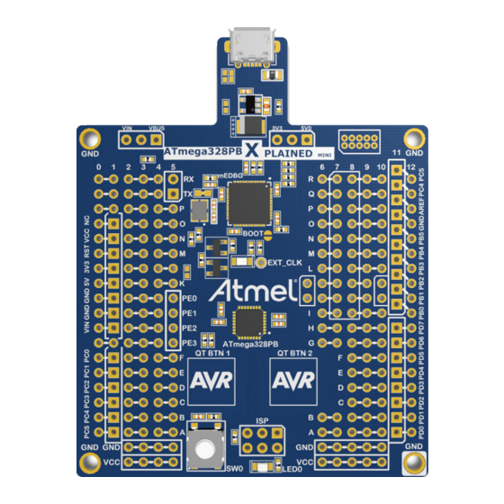
ATmega328PB Xplained Mini Introduction Features The ATmega328PB Xplained Mini evaluation kit provides a development platform for the ATmega328PB. Key Features • On-board debugger with full source-level debugging support in Atmel Studio • Auto-ID for board identification in Atmel Studio •... - Page 5 ATmega328PB Xplained Mini Figure 1-1. ATmega328PB Xplained Mini Headers and Connectors Power CDC UART Power source Status Micro USB Target power mEDBG Ground (J104) (J300) Con nector (J301) (ATmega32U4) Target I/O Shared I/Os Digital I/O High (J200) ANALOG (J203) ANALOG (J203)
-
Page 6: Getting Started
Programming and Debugging 2.3.1 Programming the Target Using mEDBG Using the Embedded Debugger on the ATmega328PB Xplained Mini board to program the ATmega328PB. User Guide DS50002660A-page 6 ©... - Page 7 ATmega328PB Xplained Mini Connect the Xplained Mini USB to the PC. Go to Atmel Studio: Click the Tools tab, select Device Programming, and select the connected mEDBG as Tool with Device as ATmega328PB and Interface to ISP, click Apply. Select "Memories", locate the source .hex or .elf file, and click Program.
-
Page 8: Debugging The Target Using Medbg
ATmega328PB Xplained Mini 2.3.2 Debugging the Target Using mEDBG Using the Embedded Debugger on the ATmega328PB Xplained Mini board to debug the ATmega328PB via debugWIRE. Start Atmel Studio. Connect the Xplained Mini USB to the PC. Open your project. Click the "Project" tab and select the project "properties", click the "Tools" tab, and select mEDBG as debugger and debugWIRE as interface. -
Page 9: Programming The Target Using An External Programmer
Connect the External Programmer USB to the PC. Connect the External Programmer to the ATmega328PB Xplained Mini board ISP connector. Go to Atmel Studio: Click the Tools tab, select Device Programming, and select the External Programmer connected as Tool with Device as ATmega328PB and Interface to ISP, click Apply. -
Page 10: Programming The Atmega32U4 Using A Bootloader
Launch Atmel Studio. Short strap J102. Open the programming dialog, select the bootloader in the tool menu. Connect the ATmega328PB Xplained Mini board USB connector to the PC. Select Device = ATmega32U4 (Device - Select). Select USB communication (Ctrl+U). Select the memory area to program (use the toggle memory button). -
Page 11: Xplained Mini
COM port unusable. The DTR signal is automatically set by some terminal software, but it may have to be manually enabled in your terminal. The mEDBG controls one status LED on the ATmega328PB Xplained Mini. The table below shows how the LED is controlled in different operation modes. -
Page 12: Medbg Configuration
ATmega328PB Xplained Mini Figure 3-1. External Clock Footprint The mEDBG CPU clock frequency depends on the selected voltage, see the table below. Table 3-2. CPU Clock vs. Voltage Target voltage mEDBG CPU clock 3.3V 8 MHz 5.0V 16 MHz mEDBG Configuration The operation of the mEDBG can be configured by writing registers in the mEDBG. No configuration is required for default operation. -
Page 13: Medbg Command Line Interface
ATmega328PB Xplained Mini Info: The fuse filter prevents users from changing critical fuses using Atmel Studio; however, it does not prevent users from setting fuses freely using the command line interface atprogram bundled with Atmel Studio. 3.2.3 mEDBG Command Line Interface... -
Page 14: Super User Fantastic Feature Enable Register
Writing the FUSE bit to 1 enables fuse protection when using Atmel Studio. The fuse protection prevents modification of specific fuses in the ATmega328PB target device that could make the mEDBG on the ATmega328PB Xplained Mini not usable. Writing the FUSE bit to 0 removes all protection of fuses in the ATmega328PB target device. - Page 15 ATmega328PB Xplained Mini Figure 3-2. Force Boot Jumper User Guide DS50002660A-page 15 © 2017 Microchip Technology Inc.
-
Page 16: Hardware User Guide
ATmega328PB Xplained Mini and their connections to the ATmega328PB. The tables of connections in the sections below also describe which signals are shared between the headers and on- board functionality. The figure below shows the assembly drawing of the ATmega328PB Xplained Mini to help identification of components. User Guide DS50002660A-page 16 ©... -
Page 17: Power Sources
Power Sources The ATmega328PB Xplained Mini kit can be powered by a USB or an external voltage input VIN. The default power source is 5.0V from a USB. The USB port is protected with a 500 mA PTC resettable fuse. -
Page 18: Board Assembly
Arduino shields can be mounted in the marked positions (J200, J201, J202, J203, and J204). Warning: The ATmega328PB Xplained Mini connects VCC_TARGET to the Arduino SPI connector, while all Arduino boards connect VCC_P5V0 to the same pin. The VCC_TARGET may be either 3.3V or 5.0V depending on the configuration of the kit if the kit is configured for 3.3V operation. -
Page 19: Board Power Header
ATmega328PB pin Function RXD (ATmega328PB USART Input Pin) TXD (ATmega328PB USART Output Pin) 4.3.2 Board Power Header J202 enables connection to the ATmega328PB Xplained Mini power system. Table 4-3. J202 Power Header J202 pin Signal Description VCC_TARGET The power source selected for the target. (Select by J301.) -
Page 20: Target Analog I/O
ATmega328PB Xplained Mini J202 pin Signal Description VCC_VIN The external power source connection. (Connected to J300 pin 3.) 4.3.3 Target Analog I/O The ATmega328PB ADC input pins are available in the J203 header. AREF is available on J200, pin 8. -
Page 21: Target Peripherals
ATmega328PB Xplained Mini ATmega328PB pin Grid position Target Peripherals The ATmega328PB Xplained Mini evaluation kit has one push button, one yellow LED, and two QTouch buttons connected to the ATmega328PB. Figure 4-3. ATmega328PB Xplained Mini Peripherals 4.4.1 Push Button A general purpose push button, SW200, is connected to PB7, as shown below. When the button is pressed, PB7 is connected to GND and is therefore active low. -
Page 22: Qtouch Buttons
D200 LED_12 EL17-21UYC/A3 4.4.3 QTouch Buttons ATmega328PB Xplained Mini implements two QTouch buttons marked QTBTN1 and QTBTN2 in the board silkscreen. To get started using the QTouch buttons open the QTouch Mega328PB Xplained Mini Selfcap Example Atmel START (http://start.atmel.com/#examples). Table 4-7. QTouch Buttons Wiring... -
Page 23: Medbg Jtag Interface
ATmega328PB Xplained Mini Table 4-8. J104 USART Header J104 pin ATmega32U4 ATmega328PB Function 1 - USART TxD PD3 PD0 (RxD) TxD out from ATmega32U4 2 - USART RxD PD2 PD1 (TxD) RxD in to ATmega32U4 4.5.2 mEDBG JTAG Interface The mEDBG (ATmega32U4) JTAG interface is available for programming and debugging of the ATmega32U4 on the 50-mil header in the upper right corner of the kit. -
Page 24: Factory Programmed
ATmega328PB Xplained Mini Using pin 11 to 20 enables connection of the 10-pin legacy header used on the RZ600 wireless modules and the 10-pin Xplained sensor modules. The general bus connections for an Xplained Pro Extension board are indicated in the table below. -
Page 25: Hardware Revision History And Known Issues
= revision s = serial number The product identifier for ATmega328PB Xplained Mini is A09-2523. Revision 4 There are no known issues with revision 4 of ATmega328PB Xplained Mini. Revision 3 Revision 3 is the initial released revision. User Guide DS50002660A-page 25 ©... - Page 26 ATmega328PB Xplained Mini Figure 5-1. ATmega328PB Xplained Mini Revision 3 Top View Figure 5-2. ATmega328PB Xplained Mini Revision 3 Top Overview User Guide DS50002660A-page 26 © 2017 Microchip Technology Inc.
-
Page 27: Engineering Samples
The remainder of this section documents the revision 3 implementation. Up to four QTouch buttons are available on the ATmega328PB Xplained Mini board. The QTouch area can be configured as buttons or as a limited slider. For a typical button or slider reference design use the QT1 Xplained Pro extension. - Page 28 ATmega328PB Xplained Mini In the default HW configuration, the QTouch area can be configured in SW as three buttons or as a limited slider. To get four buttons the S touch area can be connected to e.g. PC2 by removing the 0Ω resistor R214 and adding a wire or a 100 kΩ...
-
Page 29: Document Revision History
ATmega328PB Xplained Mini Document Revision History Document Date Comment revision 09/2017 Converted to Microchip format and replaced the Atmel document number 42469B. Updated the user guide to reflect revision 4 of the kit. Restructured the document. Added the Hardware Revision History and Known Issues chapter. -
Page 30: The Microchip Web Site
ATmega328PB Xplained Mini The Microchip Web Site Microchip provides online support via our web site at http://www.microchip.com/. This web site is used as a means to make files and information easily available to customers. Accessible by using your favorite Internet browser, the web site contains the following information: •... -
Page 31: Legal Notice
SQTP is a service mark of Microchip Technology Incorporated in the U.S.A. Silicon Storage Technology is a registered trademark of Microchip Technology Inc. in other countries. GestIC is a registered trademark of Microchip Technology Germany II GmbH & Co. KG, a subsidiary of Microchip Technology Inc., in other countries. -
Page 32: Quality Management System Certified By Dnv
ATmega328PB Xplained Mini ISBN: 978-1-5224-2118-4 Quality Management System Certified by DNV ISO/TS 16949 Microchip received ISO/TS-16949:2009 certification for its worldwide headquarters, design and wafer fabrication facilities in Chandler and Tempe, Arizona; Gresham, Oregon and design centers in California ® ®... -
Page 33: Worldwide Sales And Service
Sweden - Stockholm Tel: 408-735-9110 Tel: 86-29-8833-7252 Tel: 66-2-694-1351 Tel: 46-8-5090-4654 Tel: 408-436-4270 Fax: 86-29-8833-7256 Fax: 66-2-694-1350 UK - Wokingham Canada - Toronto Tel: 44-118-921-5800 Tel: 905-695-1980 Fax: 44-118-921-5820 Fax: 905-695-2078 User Guide DS50002660A-page 33 © 2017 Microchip Technology Inc.
Need help?
Do you have a question about the ATmega328PB Xplained Mini and is the answer not in the manual?
Questions and answers