Table of Contents
Advertisement
Quick Links
Advertisement
Table of Contents

Subscribe to Our Youtube Channel
Summary of Contents for POSIFLEX LCD Customer Display PD-7100
- Page 1 7100 Series 7200 USER’S MANUAL LCD CUSTOMER DISPLAY Rev. : A1...
-
Page 2: About This Manual
ABOUT THIS MANUAL This manual assists the user to utilize the LCD customer display PD-7100 / 7200 series. Both series provide versatile font formats and support various instruction sets. These series of products receive instructions in serial communication protocols and is capable of entering pass through mode so that all instructions received pass on to next connected serial device if properly configured. -
Page 3: Table Of Contents
TABLE OF CONTENTS GENERAL DESCRIPTION Introduction · · · · · · · · · · · · · · · · · · · · · · · · · 1 Application · · · · · · · · · · · · · · · · · · · · · · · · · · 1 Special Features ·... - Page 4 Normal Operation Ratings · · · · · · · · · · · · · · · · · · 5 OPTICAL CHARACTERISTICS Character Format · · · · · · · · · · · · · · · · · · · · · · 5 Fundamental Specification ·...
-
Page 5: General Description
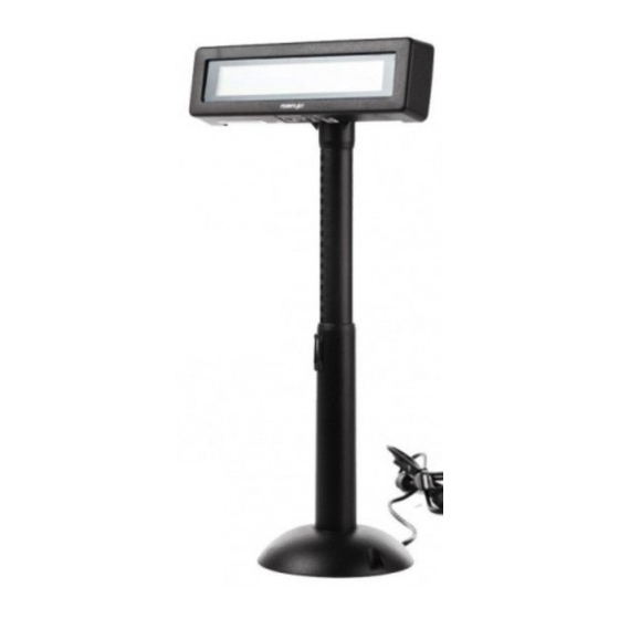
GENERAL DESCRIPTION A. Introduction This documentation describes the features and requirements of the product series of PD-7100 / 7200, a Liquid Crystal Display which is a wide customer display. It displays alphanumerical characters in 2 lines of 20 large sized characters and is able to display in 4 lines of 26 alphanumerical characters per line to show more information at a time. -
Page 6: Description
D. Description This LCD is a self-contained multiplexed unit which provides a simple interface to a microprocessor system. The display is available with one I/O connector for both the RS232 interfacing and the power supply. This unit consists of a liquid crystal display cell and a minimal amount of electronic hardware. -
Page 7: Accessories
ACCESSORIES • User’s manual • Pass through terminator (already plugged at bottom of PD) • Signal cable 20863137210 (CCBLA-372) – a DB-9F to DB-9M RS232 cable 1.8 M • Power source (one of the four below): Power adaptor specified per country type Power kit incl. -
Page 8: Installation
III. INSTALLATION A. Signal connection Connect the DB9 female connector of the signal cable CCBLA - 372 to the COM port of the host computer or POS system and connect the DB9 male connector of the signal cable CCBLA – 372 to the DB9 female connector in the base of the PD. - Page 9 3. Select one I/O plate position on rear window of PC to install the I/O plate of CCBLA-141. 4. Select one set of large 4 pin connector from the switching power supply unit of PC and connect the male 4 pin connector of CCBLA- 141 to the connector from power supply.
-
Page 10: Using Power From Pos System
3. Using power from POS system This super convenient power supply method applies only when connected to a Posiflex POS system after proper setting for power in COM port. The power connection is already done when the signal connection is completed. 4. -
Page 11: After Powering Up
Please reserve the COM port terminator in a safe place in case the non-pass- through operation would be required in the future. D. After Powering Up A firmware version as power on sign will appear on the screen for a while and the emulation mode will appear for a while after the firmware version display. -
Page 12: Dip Switch & Jumper Settings
C. Dip Switch & Jumper Settings 1. On control board in display head Emulation mode (reach the switches from outside of back of the head) EPSON 2 X 20 EPSON 4 X 26 Push up to switch on RS232 protocol (Inside display head) Short 19200, n, 8, 1 2. -
Page 13: Serial Data And Self Test
1 –2 Short -Busy status of PD sent to host as CTS and DSR at the same time Note: There must be the pass through serial output device on the pre- mounted pass through terminator connected to RS232 Out the 9 pin serial pass through port when JP2 is set to 2 –3 Short. -
Page 14: Mechanical Specifications
V. MECHANICAL SPECIFICATIONS A. Mechanical Drawings 260.0 193.0 70.0 200.0 (Lowest height) 41.0 220.0 B. Mechanical Function The pole of this customer display consists of 2 sections enabling adjustment on the height of the pole. The total height of this display is dependent on the pole adjustment, please refer to the drawings of last section The difference between maximal and minimal height is 104 mm. -
Page 15: Electrical Characteristics
VI. ELECTRICAL CHARACTERISTICS A. Power ON / OFF Sequence There are no deleterious effects associated with power ON and OFF of this display; however, rapid ON / OFF sequencing is not recommended. Neither data nor power connectors should be connected / disconnected while power is applied. B. -
Page 16: Environmental Characteristics
B. FUNDAMENTAL SPECIFICATION Number of display dot Effective display area Dot size LCD type Viewing angle Response time VIII. ENVIRONMENTAL CHARACTERISTICS Operating temperature: 0 to +50 (°C) Storage temperature: -20 to +70 (°C) Relative humidity: (≤40°C) 0 to 95 % (non-condensing) (≥40°C) Absolute humidity must be lower than the : 160 x 32 : 179.15 (W) x 36.75 (H) mm...


Need help?
Do you have a question about the LCD Customer Display PD-7100 and is the answer not in the manual?
Questions and answers