
Related Manuals for Emerson Rosemount SOLU COMP II


Summary of Contents for Emerson Rosemount SOLU COMP II
- Page 1 Instruction Manual PN 51-1055OZ/rev.K February 2006 Model SOLU COMP ® Ozone Analyzer...
- Page 2 EN50081-2. Emerson Process Management Rosemount Analytical Inc. 2400 Barranca Parkway Irvine, CA 92606 USA Tel: (949) 757-8500 Fax: (949) 474-7250 http://www.raihome.com...
- Page 3 QUICK START GUIDE FOR MODEL SOLU COMP II OZONE ANALYZER (Model Option 1055-26) 1. Refer to page 6 for installation instructions. 2. Wire ozone sensor to the analyzer. See the drawings below. Refer to the sensor instruction sheet for details. Make alarm, output, and power connections as shown below.
- Page 4 4. When the analyzer is powered up for the first time, Quick Start screens appear. Using Quick Start is easy. a. A blinking field shows the position of the cursor. b. Use the key to move the cursor left or right. Use the key to move the cursor up or down or to increase or decrease the value of a digit.
-
Page 6: Table Of Contents
MODEL SOLU COMP II TABLE OF CONTENTS MODEL SOLU COMP II DUAL INPUT OZONE ANALYZER TABLE OF CONTENTS Section Title Page DESCRIPTION AND SPECIFICATIONS ................Features and Applications ...................... Specifications ......................... Ordering Information ......................INSTALLATION........................Unpacking and Inspection ...................... Installation ..........................WIRING .......................... -
Page 7: List Of Figures
MODEL SOLU COMP II TABLE OF CONTENTS TABLE OF CONTENTS CONT’D LIST OF FIGURES Number Title Page Panel Mount Installation ................... Pipe Mount Installation ..................... Surface Mount Installation ..................Removing the Knockouts ..................Wiring Connections for Solu Comp II Model 1055pH-01-10 ........(Panel Mount with 115/230 Vac Power).............. - Page 8 Rev. Level Date Notes 9/02 This is the initial release of the product manual. The manual has been reformatted to reflect the Emerson documentation style and updated to reflect any changes in the product offering. 11/02 Deleted option code -41. 4/03 Updated CE info.
-
Page 9: Description And Specifications
MODEL SOLU COMP II SECTION 1.0 DESCRIPTION AND SPECIFICATIONS SECTION 1.0. DESCRIPTION AND SPECIFICATIONS 1.1 FEATURES AND APPLICATIONS 1.2 SPECIFICATIONS 1.3 ORDERING INFORMATION AND ACCESSORIES 1.1 FEATURES AND APPLICATIONS ENCLOSURE: The panel mount version fits stan- dard ½ DIN panel cutouts, and its shallow depth is The Solu Comp II analyzers offer the choice of sin- ideally suited for easy mounting in Hoffman-type gle or dual sensor input with measurement choices... -
Page 10: Specifications
MODEL SOLU COMP II SECTION 1.0 DESCRIPTION AND SPECIFICATIONS 1.2 SPECIFICATIONS - General RFI/EMI: EN-61326 Case: ABS (panel-mount), polycarbonate (pipe- and surface-mount). All versions are NEMA 4X/CSA 4 LVD: EN-61010-1 (IP65). Input: Choice of single or dual sensor input with Dimensions measurement choices of pH/ORP, conductivity/ Panel (code -10): 6.10 x 6.10 x 3.72 in. - Page 11 MODEL SOLU COMP II SECTION 1.0 DESCRIPTION AND SPECIFICATIONS CONTACTING CONDUCTIVITY (Codes -20 and/or -30) Measures conductivity in the range 0 to 20,000 µS/cm. RECOMMENDED SENSORS FOR CON- Display choices are conductivity, resistivity, and TDS DUCTIVITY: (total dissolved solids). Three temperature corrections The Solu Comp II is intended for use with the are available: high purity water (dilute sodium chlo- ENDURANCE Model 400 series conductivity sensor...
- Page 12 MODEL SOLU COMP II SECTION 1.0 DESCRIPTION AND SPECIFICATIONS TOROIDAL CONDUCTIVITY (Codes -21 and/or -31) When used with Model Series 200 Toroidal RECOMMENDED SENSORS: Conductivity Sensors, display choices are conductiv- Model 222 Flow-through conductivity sensor ity, resistivity, and percent concentration. The per- Model 225 Clean-in-place conductivity sensor cent concentration selection includes the choice of four common solutions (0-12% NaOH, 0-15% HCl,...
- Page 13 MODEL SOLU COMP II SECTION 1.0 DESCRIPTION AND SPECIFICATIONS pH/ORP (Codes -22 and/or -32) For use with any standard pH or ORP sensor and all RECOMMENDED SENSORS FOR pH: Uniloc sensors and junction boxes with built-in diag- Model 320B Flow Through pH nostic style preamplifiers, display choices are pH, Model 320HP High Purity pH ORP or Redox.
- Page 14 MODEL SOLU COMP II SECTION 1.0 DESCRIPTION AND SPECIFICATIONS FLOW (Standard on all models or stand alone, Code -23 and/or -33) For use with most pulse signal flow sensors, the Solu RECOMMENDED SENSORS Comp II's user selectable units of measure include +GF+ Signet 515 Rotor-X Flow sensor Model flow rates in GPM (Gallon per minute), LPM (liters per 515/8510-XX (PN P51530-PO)
- Page 15 MODEL SOLU COMP II SECTION 1.0 DESCRIPTION AND SPECIFICATIONS DISSOLVED OXYGEN (Code -25) The Solu Comp II is compatible with the Model PERFORMANCE SPECIFICATIONS 499ADO, 499ATrDO, Hx438, and Gx438 dissolved Measurement Range: 0-20 ppm (mg/L) dissolved oxygen sensors. The sensors are membrane-covered oxygen;...
-
Page 16: Ordering Information
MODEL SOLU COMP II SECTION 1.0 DESCRIPTION AND SPECIFICATIONS 1.3 ORDERING INFORMATION The Solu Comp II analyzers offer the choice of single or dual sensor input with measurement choices of pH/ORP, conductivi- ty/resistivity, toroidal conductivity, flow, ozone, dissolved oxygen, and dissolved ozone. See combination guide (on the follow- ing page) for valid combinations. - Page 17 MODEL SOLU COMP II SECTION 1.0 DESCRIPTION AND SPECIFICATIONS COMBINATION GUIDE * For D.O. sensors with 22k thermistor, use Suite 1 only.
- Page 18 MODEL SOLU COMP II SECTION 1.0 DESCRIPTION AND SPECIFICATIONS ACCESSORIES (Weights are rounded up to nearest whole lb or 0.5 kg) PART NUMBER DESCRIPTION WEIGHT SHIPPING WT. 23820-00 Pipe mounting kit, includes U-bolts, mounting bracket, nuts, 2 lb (1.0 kg) 4 lb (2.0 kg) washers, and screws (complete) 23554-00...
-
Page 19: Installation
MODEL SOLU COMP II SECTION 2.0 INSTALLATION SECTION 2.0. INSTALLATION 2.1 UNPACKING AND INSPECTION 2.2 INSTALLATION 2.1 UNPACKING AND INSPECTION Inspect the shipping container. If it is damaged, contact the shipper immediately for instructions. Save the box. If there is no apparent damage, unpack the container. Be sure all items shown on the packing list are present. If items are missing, notify Rosemount Analytical immediately. -
Page 20: Panel Mount Installation
MODEL SOLU COMP II SECTION 2.0 INSTALLATION 2.2.2 Panel Mounting. MILLIMETER INCH FIGURE 2-1. Panel Mount Installation Access to the wiring terminals is through the rear cover. Four screws hold the cover in place. -
Page 21: Pipe Mount Installation
MODEL SOLU COMP II SECTION 2.0 INSTALLATION 2.2.3 Pipe Mounting. MILLIMETER INCH FIGURE 2-2. Pipe Mount Installation The front panel is hinged at the bottom. The panel swings down for access to the wiring terminals. -
Page 22: Surface Mount Installation
MODEL SOLU COMP II SECTION 2.0 INSTALLATION 2.2.4 Surface Mounting. MILLIMETER INCH FIGURE 2-4. Surface Mount Installation The front panel is hinged at the bottom. The panel swings down for access to the wiring terminals. -
Page 23: Wiring
MODEL SOLU COMP II SECTION 3.0 WIRING SECTION 3.0. WIRING 3.1 PREPARING CONDUIT OPENINGS 3.2 POWER, ALARM, AND OUTPUT CONNECTIONS 3.3 SENSOR CONNECTIONS 3.1 PREPARING CONDUIT OPENINGS The number of conduit openings and the location depend on the model. Model Description Conduit openings 1055-10... - Page 24 MODEL SOLU COMP II SECTION 3.0 WIRING FIGURE 3-2. Wiring Connections for Solu Comp II Model FIGURE 3-3. Wiring Connections for Solu Comp II Model 1055-01-10 (Panel Mount with 115/230 Vac Power) 1055-02-10 (Panel Mount with 24 Vdc Power) FIGURE 3-4. Wiring Connections for Solu Comp II Model FIGURE 3-5.
-
Page 25: Sensor Connections
MODEL SOLU COMP II SECTION 3.0 WIRING 3.3 SENSOR CONNECTIONS Refer to the table to select the correct wiring diagram. 1055 configuration Sensor cable Figure Panel mounting Standard EMI/RFI; Variopol Wall/pipe mounting Standard EMI/RFI; Variopol FIGURE 3-6. Wiring Sensor with Standard Cable to FIGURE 3-7. -
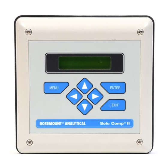
Page 26: Display And Operation
MODEL SOLU COMP II SECTION 4.0 DISPLAY AND OPERATION SECTION 4.0 DISPLAY AND OPERATION 4.1 DISPLAY 4.2 KEYPAD 4.3 PROGRAMMING AND CALIBRATING THE SOLU COMP II - TUTORIAL 4.4 SECURITY 4.5 USING HOLD 4.1. DISPLAY The Solu Comp II has a two-line display. The display can be customized to meet user requirements (see Section 5.10). -
Page 27: Programming And Calibrating The Solu Comp Ii - Tutorial
MODEL SOLU COMP II SECTION 4.0 DISPLAY AND OPERATION 4.3 PROGRAMMING AND CALIBRATING THE SOLU COMP II - TUTORIAL Setting up and calibrating the Solu Comp II is easy. The following tutorial describes how to move around in the programming menus. For practice, the tutorial also describes how to assign chlorine values to the 4 and 20 mA out- puts for sensor 1. -
Page 28: Security
MODEL SOLU COMP II SECTION 4.0 DISPLAY AND OPERATION 4.4 SECURITY 4.4.1 How the Security Code Works Use the security code to prevent accidental or unwanted changes to program settings, displays, and calibration. 1. If a security code has been programmed, pressing MENU causes the Enter Security security screen to appear. -
Page 29: Programming The Analyzer
MODEL SOLU COMP II SECTION 5.0 PROGRAMMING THE ANALYZER SECTION 5.0 PROGRAMMING THE ANALYZER 5.1 GENERAL 5.2 CHANGING STARTUP SETTINGS 5.3 CONFIGURING AND RANGING THE OUTPUTS 5.4 CONFIGURING ALARMS AND ASSIGNING SETPOINTS 5.5 SETTING THE INPUT FILTER 5.6 CHOOSING TEMPERATURE UNITS AND MANUAL OR AUTOMATIC TEM- PERATURE COMPENSATION 5.7 SETTING A SECURITY CODE 5.8 NOISE REJECTION... -
Page 30: Default Settings
MODEL SOLU COMP II SECTION 5.0 PROGRAMMING THE ANALYZER TABLE 5-1. DEFAULT SETTINGS 1. OTHER OUTPUT SETTINGS Output Assignment Range Current Dampening Mode Section ozone 0 - 10 ppm 4 - 20 mA linear 5.3 and 5.9 temperature 0 - 100°C 4 - 20 mA linear 5.3 and 5.9... -
Page 31: Configuring And Ranging The Outputs
MODEL SOLU COMP II SECTION 5.0 PROGRAMMING THE ANALYZER 5.3 CONFIGURING AND RANGING THE OUTPUTS. 5.3.1 Purpose The Solu Comp II has two current outputs. This section describes how to configure and range the outputs. CONFIGURE THE OUTPUTS FIRST. 1. Configuring an output means a. - Page 32 MODEL SOLU COMP II SECTION 5.0 PROGRAMMING THE ANALYZER 5.3.3. Procedure: Configure Outputs. To choose a menu item, move the cursor to the item and press ENTER. To store a number or setting, press ENTER. 1. Press MENU. The main menu screen appears. Choose Program. Calibrate Hold P P r r o o g g r r a a m m...
-
Page 33: Configuring Alarms And Assigning Setpoints
MODEL SOLU COMP II SECTION 5.0 PROGRAMMING THE ANALYZER 5.4 CONFIGURING ALARMS AND ASSIGNING SETPOINTS 5.4.1 Purpose This section describes how to do the following: 1. assign an alarm relay to the ozone reading or temperature or use it to signal a fault condition, 2. - Page 34 MODEL SOLU COMP II SECTION 5.0 PROGRAMMING THE ANALYZER 5.4.3 Procedure: Configuring Alarms To choose a menu item, move the cursor to the item and press ENTER. To store a number or setting, press ENTER. 1. Press MENU. The main menu screen appears. Choose Program. Calibrate Hold P P r r o o g g r r a a m m...
- Page 35 MODEL SOLU COMP II SECTION 5.0 PROGRAMMING THE ANALYZER 5.4.4 Procedure: Programming Alarm Setpoints To choose a menu item, move the cursor to the item and press ENTER. To store a number or setting, press ENTER. Calibrate Hold 1. Press MENU. The main menu screen appears. Choose Program. P P r r o o g g r r a a m m Display Outputs...
-
Page 36: Selecting The Amount Of Filtering
MODEL SOLU COMP II SECTION 5.0 PROGRAMMING THE ANALYZER SELECTING THE AMOUNT OF FILTERING 5.5.1 Purpose This section describes how to change the amount of electronic filtering of the sensor current. 5.5.2 Definitions INPUT FILTER. Before converting the sensor current to a ozone reading, the Solu Comp II applies an input filter. The filter reduces noisy readings, but increases the response time. -
Page 37: Choosing Temperature Units And Manual/Automatic Temperature Compensation
MODEL SOLU COMP II SECTION 5.0 PROGRAMMING THE ANALYZER 5.6 CHOOSING TEMPERATURE UNITS AND MANUAL OR AUTOMATIC TEMPERATURE COMPENSATION 5.6.1 Purpose This section describes how to do the following: 1. Choose temperature display units (°C or °F). 2. Choose automatic or manual temperature compensation for membrane permeability. 3. -
Page 38: Setting A Security Code
MODEL SOLU COMP II SECTION 5.0 PROGRAMMING THE ANALYZER 5.7 SETTING A SECURITY CODE 5.7.1 Purpose. This section describes how to set a security code. The security code prevents program and calibration settings from accidentally being changed. Refer to Section 4.4 for additional information. 5.7.2 Procedure. -
Page 39: Resetting Factory Calibration And Factory Default Settings
MODEL SOLU COMP II SECTION 5.0 PROGRAMMING THE ANALYZER 5.9 RESETTING FACTORY CALIBRATION AND FACTORY DEFAULT SETTINGS 5.9.1 Purpose. This section describes how to re-install factory calibration and default values. The process also clears all fault mes- sages and returns the display to the first quick start screen. 5.9.2. -
Page 40: Selecting A Default Screen, Language, And Screen Contrast
MODEL SOLU COMP II SECTION 5.0 PROGRAMMING THE ANALYZER 5.10 SELECTING A DEFAULT SCREEN, LANGUAGE, AND SCREEN CONTRAST 5.10.1 Purpose This section describes how to do the following: 1. set a default display screen (The default display screen is the screen shown during normal operation.) 2. -
Page 41: Calibration
MODEL SOLU COMP II SECTION 6.0 CALIBRATION SECTION 6.0 CALIBRATION INTRODUCTION CALIBRATING TEMPERATURE CALIBRATING OZONE 6.1 INTRODUCTION The Calibrate Menu allows the user to calibrate the ozone sensor. Both the ppm reading and the temperature can be calibrated. Ozone sensors require periodic full-scale calibration. The purpose of the full-scale standard is to establish the slope of the calibration curve. - Page 42 MODEL SOLU COMP II SECTION 6.0 CALIBRATION 6.2.2 Procedure 1. Remove the sensor from the process. Place it in an insulated container of water along with a calibrated ther- mometer. Submerge at least the bottom two inches of the sensor. Stir continuously. 2.
-
Page 43: Calibrating Ozone
MODEL SOLU COMP II SECTION 6.0 CALIBRATION 6.3 CALIBRATION — OZONE As Figure 6-1 shows, an ozone sensor generates a current directly proportional to the concentration of ozone in the sample. Calibrating the sensor requires exposing it to a solution containing no ozone (zero standard) and to a solution containing a known amount of ozone (full-scale standard). - Page 44 MODEL SOLU COMP II SECTION 6.0 CALIBRATION 6.3.2 Procedure — Zeroing the sensor. 1. Place the sensor in the zero standard. Be sure no air bubbles are trapped against the membrane. The sensor current will drop rapidly at first and then gradually reach a stable zero value. To monitor the sensor current, go to the main display and press until the sensor input current is showing.
- Page 45 MODEL SOLU COMP II SECTION 6.0 CALIBRATION 6.3.3 Procedure — Calibrating the sensor 1. Place the sensor in the process liquid. Adjust the sample flow until it is in the range recommended for the ozone sensor. Refer to the sensor instruction sheet. 2.
-
Page 46: Maintenance
MODEL SOLU COMP II SECTION 7.0 MAINTENANCE SECTION 7.0 MAINTENANCE 7.1 OVERVIEW 7.2 REPLACEMENT PARTS 7.1 OVERVIEW The Solu Comp II analyzer needs little routine maintenance. The calibration of the analyzer and sensor should be checked periodically. To recalibrate the analyzer and sensor, see Section 6.0. Clean the analyzer case and front panel by wiping with a clean soft cloth dampened with water ONLY. -
Page 47: Exploded View Of Solu Comp Ii (Panel Mount Version)
MODEL SOLU COMP II SECTION 7.0 MAINTENANCE TABLE 7-1. Replacement Parts for Solu Comp II (Panel Mount Version) Location in Shipping Figure 7-1 Description Weight 23823-00 Panel mounting kit, includes four brackets and 2 lb/1.0 kg four set screws 23837-00 Enclosure, front, for panel mount version, includes keypad 3 lb/1.0 kg 33654-00... -
Page 48: Exploded View Of Solu Comp Ii (Pipe/Surface Mount Version)
MODEL SOLU COMP II SECTION 7.0 MAINTENANCE TABLE 7-2. Replacement Parts for Solu Comp II (Pipe/Surface Mount Version) Location in Shipping Figure 7-2 Description Weight note Screw, 6-32 x 1.38 in. note Washer 23834-00 Enclosure, front, for pipe/surface mount version, 2 lb/1.0 kg includes keypad and hinge 33655-00... -
Page 49: Troubleshooting
MODEL SOLU COMP II SECTION 8.0 TROUBLESHOOTING SECTION 8.0 TROUBLESHOOTING 8.1 OVERVIEW 8.2 TROUBLESHOOTING USING FAULT CODES 8.3 TROUBLESHOOTING WHEN NO ERROR MESSAGE IS SHOWING — OZONE 8.4 TROUBLESHOOTING WHEN NO ERROR MESSAGE IS SHOWING — GENERAL 8.5 SIMULATING INPUTS 8.6 SIMULATING TEMPERATURE 8.1 OVERVIEW The Solu Comp II continuously monitors itself and the sensor for faults. - Page 50 MODEL SOLU COMP II SECTION 8.0 TROUBLESHOOTING 8.2.3 RTD Sense Line for Sensor 1 is Open. The Solu Comp II measures temperature using a three-wire RTD. See Figure 8-4. The in and return leads connect the RTD to the measuring circuit in the analyzer. A third wire, called the sense line, is connected to the return line at the sensor.
-
Page 51: Troubleshooting When No Error Message Is Showing - Ozone
MODEL SOLU COMP II SECTION 8.0 TROUBLESHOOTING 8.3 TROUBLESHOOTING WHEN NO ERROR MESSAGE IS SHOWING — OZONE Problem See Section Zero current was accepted, but the current is outside the range -10 to 10 nA 8.3.1 Error or warning message appears while zeroing the sensor (zero current is too high) 8.3.1 Zero current is unstable 8.3.2... - Page 52 MODEL SOLU COMP II SECTION 8.0 TROUBLESHOOTING 8.3.3 Sensor can be calibrated, but the current is too low A. Is the temperature low? Sensor current is a strong function of temperature. The sensor current decreases about 3% for every °C drop in temperature. B.
- Page 53 MODEL SOLU COMP II SECTION 8.0 TROUBLESHOOTING 8.3.7 Ozone readings are too low. A. Was the sample tested as soon as it was taken? Ozone solutions are unstable. Test the sample immediately after collecting it. B. Low readings can be caused by zeroing the sensor before the residual current has reached a stable minimum value.
-
Page 54: Troubleshooting When No Error Message Is Showing - General
MODEL SOLU COMP II SECTION 8.0 TROUBLESHOOTING 8.4 TROUBLESHOOTING WHEN NO ERROR MESSAGE IS SHOWING — GENERAL Problem See Section New temperature during calibration more than 2-3ºC different from the live reading 8.4.1 Current output is too low 8.4.2 Alarm relays do not operate when setpoint is exceeded 8.4.3 Display is unreadable —... -
Page 55: Simulating Temperature
MODEL SOLU COMP II SECTION 8.0 TROUBLESHOOTING 8.6 SIMULATING TEMPERATURE 8.6.1 General. The Solu Comp II accepts a Pt100 RTD. The Pt100 RTD is in a three-wire configuration. See Figure 8-2. 8.6.2 Simulating temperature FIGURE 8-2. Three-Wire RTD Configuration. To simulate the temperature input, wire a decade box to Although only two wires are required to connect the analyzer or junction box as shown in Figure 8-3. -
Page 56: Return Of Material
Carefully package the materials and enclose your “Letter of Transmittal” (see Warranty). If possible, pack the materials in the same manner as they were received. Send the package prepaid to: Emerson Process Management, Liquid Division Liquid Division 2400 Barranca Parkway... - Page 57 NESS FOR PARTICULAR PURPOSE, OR ANY OTHER MATTER WITH RESPECT TO ANY OF THE GOODS OR SERVICES. RETURN OF MATERIAL Material returned for repair, whether in or out of warranty, should be shipped prepaid to: Emerson Process Management Liquid Division 2400 Barranca Parkway...
- Page 58 ON-LINE ORDERING NOW AVAILABLE ON OUR WEB SITE right now. http://www.raihome.com Specifications subject to change without notice. Credit Cards for U.S. Purchases Only. Emerson Process Management Liquid Division 2400 Barranca Parkway Irvine, CA 92606 USA Tel: (949) 757-8500 Fax: (949) 474-7250 http://www.raihome.com...
Need help?
Do you have a question about the Rosemount SOLU COMP II and is the answer not in the manual?
Questions and answers