Table of Contents
Advertisement
Quick Links
Advertisement
Table of Contents

Related Manuals for Pentair AUTOTROL 604


Summary of Contents for Pentair AUTOTROL 604
- Page 1 AUTOTROL 368 / 604-606...
-
Page 2: Table Of Contents
Installer Manual Autotrol 368 / 604-606 - Table of content Table of content Generalities ......... . 5 1.1. - Page 3 Installer Manual Autotrol 368 / 604-606 - Table of content Installation ......... . 18 5.1.
- Page 4 Installer Manual Autotrol 368 / 604-606 - Table of content Operation ......... . . 35 8.1.
-
Page 5: Generalities
Revision Date Author Description 16.12.2016 First edition 1.3. Manufacturer identifier, product Manufacturer: Pentair Manufacturing Italy Srl Via Masaccio, 13 56010 Lugnano di Vicopisano (PI) – Italy Product: Autotrol 368 / 604-606 Ref. MKT-IM-007 / A - 16.12.2016 5 / 54... -
Page 6: Abbreviations Used
Installer Manual Autotrol 368 / 604-606 - Generalities 1.4. Abbreviations used DF............Down Flow Inj ............Injector DLFC ............Drain Line Flow Controller BLFC / Refill Flow Controller....Brine Line Flow Controller QC............Quick Connect Regen ............Regeneration SBV............Safety Brine Valve TC ............ -
Page 7: Copyright
Pentair Quality System EMEA products benefit, under specific conditions, from a manufacturer warranty that may be invoked by Pentair’s direct customers. Users should contact the vendor of this product for applicable conditions and in case of a potential warranty claim. -
Page 8: Safety
Installer Manual Autotrol 368 / 604-606 - Safety Safety 2.1. Safety pictograms definition Caution Warning Warns of a risk of minor injury or major Warns against serious personal injury material damage to the device or and damage to health. environment. Danger... -
Page 9: Hazards
Installer Manual Autotrol 368 / 604-606 - Safety 2.3. Hazards All the safety and protection instructions contained in this document must be observed in order to avoid temporary or permanent injury, damage to property or environmental pollution. At the same time, any other legal regulations, accident prevention and environmental protection measures, as well as any recognized technical regulations relating to appropriate and risk-free methods of working which apply in the country and place of use of the device must be adhered to. -
Page 10: Hygiene Measures
Installer Manual Autotrol 368 / 604-606 - Safety Assembly • Assemble only with components which are in accordance with the drinking water standards (DM 174, ACS, WRAS, KTW, etc...). • After installation and before use, perform one or more manual regenerations in order to clean the media bed. -
Page 11: Description
Riser tube length ........Flush to top of tank ± 12.7 mm (½") Electrical Controller Operating Voltage ....12 VAC (requires use of Pentair Water supplied transformer) Input Supply Frequency......50 or 60 Hz Motor Input Voltage ........ 12 VAC Controller Power Consumption ..... -
Page 12: Performance Flow Rate Characteristics
Installer Manual Autotrol 368 / 604-606 - Description 3.1.1. Performance flow rate characteristics The graph shows the pressure drop created by the valve itself at different flow rates. It makes it possible to predetermine the maximum flow rate going through the valve depending on the system settings (inlet pressure etc). -
Page 13: Description And Components Location
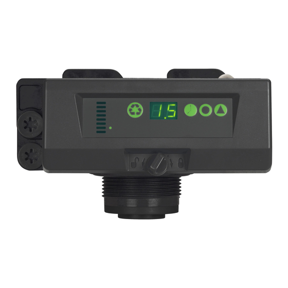
Installer Manual Autotrol 368 / 604-606 - Description 3.3. Description and components location Time button Display Delayed regeneration indicator Salt button Regeneration button Camshaft indicator Regeneration setting button Injector / screen Turbine (368 / 606 only) Refill flow controller Flow indicator Valve connection Cover locker Cable gland (368 / 606 only) -
Page 14: System Regeneration Cycle (8-Cycles Operation)
Installer Manual Autotrol 368 / 604-606 - Description 3.4. System regeneration cycle (8-cycles operation) Service (downflow) — cycle C0 Untreated water is directed down through the resin bed and up through the riser tube. The hardness ions attach themselves to the resin and are removed from the raw water being exchanged on the resin beads against by sodium ions. - Page 15 Installer Manual Autotrol 368 / 604-606 - Description Note For illustration purpose only. Always verify inlet and outlet marking on the valve. From brine tank Valve Valve Valve SERVICE BACKWASH BRINE DRAW / SLOW RINSE C1 and C5 To brine Tank Valve Valve Valve...
-
Page 16: System Sizing
Installer Manual Autotrol 368 / 604-606 - System sizing System sizing 4.1. Recommendations 4.1.1. Injector/DLFC/Refill flow controller - Valve configuration Refill flow Backwash flow Controller Vessel Injector Flow control control diameter [In] control Time Clock 604 Volumetric 606 [gpm] [gpm] E [yellow] 0.14 4001737... -
Page 17: Injection Flow Rates
Installer Manual Autotrol 368 / 604-606 - System sizing 4.3. Injection flow rates The following graphs represent the injectors flow rate as a function of the inlet pressure for the different injector sizes. BRINE DRAW RINSE TOTAL Injector "F" (Peach) Injector "G"... -
Page 18: Installation
Installer Manual Autotrol 368 / 604-606 - Installation Installation 5.1. Safety notices for installation • Observe all warnings that appear in this manual. • Only qualified and professional personnel are authorized to carry out installation work. 5.2. Installation environment 5.2.1. General •... -
Page 19: Mechanical
Installer Manual Autotrol 368 / 604-606 - Installation 5.2.3. Mechanical • Do not use petroleum-based lubricants such as vaseline, oils, or hydrocarbon-based lubricants. Use only 100% silicone lubricants. • All plastic connections should be hand tightened. PTFE (plumber’s tape) may be used on connections that do not use an O-ring seal. -
Page 20: Block Diagram And Configuration Example
Installer Manual Autotrol 368 / 604-606 - Installation 5.4. Block diagram and configuration example Configuration example Block diagram By-pass Main inlet Gauge Gauge User’s line Check valve to prevent water hammer and eventual hot water returns. Drain Valve Brine line Suggested options Resin tank 20 / 54... -
Page 21: Valve Connection To Piping
Installer Manual Autotrol 368 / 604-606 - Installation 5.5. Valve connection to piping The connections should be hand tightened using PTFE (plumber’s tape) on the threads if using the threaded connection type. In case of heat welding (metal type connection), the connections should not be made to the valve when soldering. - Page 22 • In any case, any failure causes by improper installations and/or piping connections may void the warranty of Pentair products. • In the same way, using lubricant* on the valve thread is not allowed and will void the warranty for the valve and tank.
-
Page 23: Connections (Electrical)
Installer Manual Autotrol 368 / 604-606 - Installation 5.6. Connections (electrical) AC adapter cable connection Motor and optical sensor cable connection AC adapter connection Meter cable connection (368 / 606 only) 5.7. Drain line flow controller The DLFC requires assembly before use. Note... -
Page 24: Bypassing
Installer Manual Autotrol 368 / 604-606 - Installation 5.8. Bypassing A bypass valve system should be installed on all water conditioning systems. Bypass valves isolate the conditioner from the water system and allow unconditioned water to be used during regeneration or maintenance operations. - Page 25 Installer Manual Autotrol 368 / 604-606 - Installation To remove a clip: Turn off water and release water pressure at the valve. Push the water line connectors (3) into the bypass and valve. This will help release O-rings that may have seated in place. Remove the clips (1) by inserting a flat screwdriver (2) under the top centre of the clip and lifting (prying up).
-
Page 26: Drain Line Connection
Installer Manual Autotrol 368 / 604-606 - Installation 5.9. Drain line connection Note Standard commercial practices are expressed here. Local codes may require changes to the following suggestions. Check with local authorities before installing a system. The unit should be above and not more than 6.1 m from the drain. Use an appropriate adapter fitting to connect 12.7 mm (1/2") plastic tubing to the drain line connection of the control valve. -
Page 27: Overflow Line Connection
Installer Manual Autotrol 368 / 604-606 - Installation 5.10. Overflow line connection In the event of a malfunction, the brine tank overflow fitting will direct “overflow” to the drain instead of spilling on the floor. This fitting should be on the side of the cabinet or brine tank. Most tank manufacturers include a post for the tank overflow connector. -
Page 28: Programming
Installer Manual Autotrol 368 / 604-606 - Programming Programming Note After 5 seconds without keypad input, the unit returns to normal operation mode and display the time of day. Note Memory retention in case of power failure : the controller stores the time of day without battery in case of power failure. -
Page 29: Time Clock Regeneration (604 Only)
Installer Manual Autotrol 368 / 604-606 - Programming 6.3. Time clock regeneration (604 only) Set the time between each regeneration. Press until desired interval appears then release. → Range from 0 through 30; 0 = Disabled; 0.3 = Regeneration every 8 hours : at 2, 10 and 18 hours; 0.5 = Regeneration every 12 hours : at 2 and 14 hours;... -
Page 30: System Selection
Installer Manual Autotrol 368 / 604-606 - Programming 6.6. System selection The 604 / 606 controller has four system settings available. The system selections accommodate multiple tank sizes and various feedwater conditions. System selection: Press and hold simultaneously for 3 seconds. →... -
Page 31: History Values
Installer Manual Autotrol 368 / 604-606 - Programming 6.8. History values The controller features a review level that displays the operation history of the system. To access history values : Press and hold simultaneously for 3 seconds. → To view the "H" levels. Press to navigate through the table. -
Page 32: Commissioning
Installer Manual Autotrol 368 / 604-606 - Commissioning Commissioning 7.1. Water filling, draining and waterproofness inspection 7.1.1. Start up procedure 1. With the bypass still in Bypass position (inlet and outlet manual valve closed), plug in the 600 series controller to the power source. 2. -
Page 33: Additional Tips
Installer Manual Autotrol 368 / 604-606 - Commissioning Caution Ensure that the system has been properly disinfected by the water conditioning system manufacturer’s recommendations. The water conditioning system is now fully operational. The display will show the hour of the day and the decimal point at the bottom centre of the display will blink when water is flowing. -
Page 34: Sodium Or Calcium Hypochlorite
Installer Manual Autotrol 368 / 604-606 - Commissioning 7.2.2. Sodium or calcium hypochlorite These materials are satisfactory for use with polystyrene resins, synthetic gel zeolite, greensand and bentonites. 5.25% Sodium hypochlorite If stronger solutions are used, such as those sold for commercial laundries, adjust the dosage accordingly. -
Page 35: Operation
Installer Manual Autotrol 368 / 604-606 - Operation Operation During a regeneration: • The controller displays a cascading symbol "--". Press to display the current cycle "C#"or the "--". 8.1. Recommendations • Use only regeneration salts designed for water softening EN973. •... -
Page 36: To Advance Regeneration Cycles
Installer Manual Autotrol 368 / 604-606 - Operation 8.3. To advance regeneration cycles Simultaneously press to advance to the next cycle. → When the camshaft reaches the next cycle, "C#” will be displayed. Repeat to advance through each cycle. 8.4. To cancel a regeneration Press and hold for 3 seconds during any regeneration cycle to cancel it. -
Page 37: Maintenance
Installer Manual Autotrol 368 / 604-606 - Maintenance Maintenance Mandatory Cleaning and maintenance shall take place at regular intervals in order to guarantee the proper functioning of the complete system, and be documented in the Maintenance chapter in the User Guide document. 9.1. -
Page 38: Cleaning The Refill Flow Controller
Installer Manual Autotrol 368 / 604-606 - Maintenance 9.2.2. Cleaning the refill flow controller Operation Using a Torx key, unscrew and extract the refill flow controller (4). Clean the refill flow controller (4) using compressed air or with a soft brush. Make sure the refill controller groove is perfectly clean. - Page 39 Installer Manual Autotrol 368 / 604-606 - Maintenance Ref. MKT-IM-007 / A - 16.12.2016 39 / 54...
-
Page 40: Cleaning The Backwash Flow Controller
Installer Manual Autotrol 368 / 604-606 - Maintenance 9.2.4. Cleaning the backwash flow controller Operation Remove the clip (1). Unscrew the backwash controller (4) by hand. Caution Pay attention to not lose the backwash controller ball (3) that is inside. Clean the backwash controller (4) using a soft brush or compressed air. -
Page 41: Removing The Manifold / Bypass
Installer Manual Autotrol 368 / 604-606 - Maintenance 9.2.5. Removing the manifold / bypass Note Depending on the installation configuration, the valve may be equipped with a manifold or a bypass. The following procedure applies to both configuration. Operation Remove the "U" clips (1) (a screwdriver can be used as a lever if required). Remove the manifold / bypass (2) from the valve body (3). -
Page 42: Motor And Camshaft Replacement
Installer Manual Autotrol 368 / 604-606 - Maintenance 9.2.6. Motor and camshaft replacement Operation Turn the locking clip (3) on the left to unlock the controller (2). Remove the controller (2) from the valve body (1). Caution Be careful with cables connections when disassembling the controller (2). Loosen the screws (6) and remove the clamp (5). - Page 43 Installer Manual Autotrol 368 / 604-606 - Maintenance Ref. MKT-IM-007 / A - 16.12.2016 43 / 54...
-
Page 44: Cleaning Or Replacing The Flappers
Installer Manual Autotrol 368 / 604-606 - Maintenance 9.2.7. Cleaning or replacing the flappers Operation Note To replace or clean the flappers, you first have to disassemble the camshaft and the motor. See “Motor and camshaft replacement”, page 42. The optical sensor (5) is clipped on the front edge, gently press on the clips to release the optical sensor (5) from its location. - Page 45 Installer Manual Autotrol 368 / 604-606 - Maintenance Ref. MKT-IM-007 / A - 16.12.2016 45 / 54...
-
Page 46: Troubleshooting
Installer Manual Autotrol 368 / 604-606 - Troubleshooting Troubleshooting Err. code Cause Solution Program settings have been Press any button. If "E 1" does not corrupted. clear. Replace the controller. Controller does not detect the Wait until the controller returns to the camshaft position and is returning to service position. - Page 47 Installer Manual Autotrol 368 / 604-606 - Troubleshooting Issue Cause Solution Ensure all brine line connections are Loose in brine line connection. tight. Brine tank overflow. Clean the drain controller. See 9.2. Drain line restricted with debris. Cleaning and maintenance, page 37. Debris is preventing #3 or #4 valve Remove debris.
- Page 48 Installer Manual Autotrol 368 / 604-606 - Troubleshooting Issue Cause Solution No brine in brine tank. Add brine to brine tank. No conditioned Clean the injector and screen. See water after Injector plugged. 9.2.4. Cleaning the backwash flow regeneration. controller, page 40. Incorrect drain controller used.
-
Page 49: Spare Parts
Installer Manual Autotrol 368 / 604-606 - Spare parts Spare parts Note There are no user serviceable parts in the AC wall mount adapters, motor or control board. 11.1. 368 - 604 parts lists Packaging Item Part number Description quantity AC wall mount adapters 1000810 100 VAC, 50/60 Hz, Japanese plug... - Page 50 Installer Manual Autotrol 368 / 604-606 - Spare parts Packaging Item Part number Description quantity 3022576 Power cable, optic sensor 3007947 Valve disc kit, 368 valve 3022012 Top plate 1235373 Optic sensor 1234170 Screw, top plate 3022017 Spring, top plate 3022014 Camshaft, 7 cycle 1000589...
-
Page 51: 368 - 606 Parts Lists
Installer Manual Autotrol 368 / 604-606 - Spare parts 11.2. 368 - 606 parts lists Packaging Item Part number Description quantity AC Wall Mount Adapters 1000810 100 VAC, 50/60 Hz, Japanese plug 1000811 120 VAC, 60 Hz, N. American plug 1000812 230 VAC, 50 Hz, Australian plug 1000813... - Page 52 Installer Manual Autotrol 368 / 604-606 - Spare parts Packaging Item Part number Description quantity 1234170 Screw, top plate 3022017 Spring, top plate 3022014 Camshaft, 7 cycle 1000589 Yoke, camshaft 1234170 Screw, yoke 3026537 12 volt motor / cable assembly 4001742 606 controller for use with 0.33 gpm refill flow 4001738...
-
Page 53: Scrapping
This will help to reduce the impact on the environment, health, safety and help to promote recycling. Pentair do not collect used product for recycling. Contact your local recycling centre for more information. - Page 54 www.pentairaquaeurope.com...
Need help?
Do you have a question about the AUTOTROL 604 and is the answer not in the manual?
Questions and answers